EP0416227A1 - Motor vehicle transmission - Google Patents
Motor vehicle transmission Download PDFInfo
- Publication number
- EP0416227A1 EP0416227A1 EP90111928A EP90111928A EP0416227A1 EP 0416227 A1 EP0416227 A1 EP 0416227A1 EP 90111928 A EP90111928 A EP 90111928A EP 90111928 A EP90111928 A EP 90111928A EP 0416227 A1 EP0416227 A1 EP 0416227A1
- Authority
- EP
- European Patent Office
- Prior art keywords
- gear
- selector lever
- motor vehicle
- vehicle transmission
- display
- Prior art date
- Legal status (The legal status is an assumption and is not a legal conclusion. Google has not performed a legal analysis and makes no representation as to the accuracy of the status listed.)
- Granted
Links
Images


Classifications
-
- F—MECHANICAL ENGINEERING; LIGHTING; HEATING; WEAPONS; BLASTING
- F16—ENGINEERING ELEMENTS AND UNITS; GENERAL MEASURES FOR PRODUCING AND MAINTAINING EFFECTIVE FUNCTIONING OF MACHINES OR INSTALLATIONS; THERMAL INSULATION IN GENERAL
- F16H—GEARING
- F16H59/00—Control inputs to control units of change-speed-, or reversing-gearings for conveying rotary motion
- F16H59/02—Selector apparatus
- F16H59/0204—Selector apparatus for automatic transmissions with means for range selection and manual shifting, e.g. range selector with tiptronic
-
- F—MECHANICAL ENGINEERING; LIGHTING; HEATING; WEAPONS; BLASTING
- F16—ENGINEERING ELEMENTS AND UNITS; GENERAL MEASURES FOR PRODUCING AND MAINTAINING EFFECTIVE FUNCTIONING OF MACHINES OR INSTALLATIONS; THERMAL INSULATION IN GENERAL
- F16H—GEARING
- F16H63/00—Control outputs from the control unit to change-speed- or reversing-gearings for conveying rotary motion or to other devices than the final output mechanism
- F16H63/40—Control outputs from the control unit to change-speed- or reversing-gearings for conveying rotary motion or to other devices than the final output mechanism comprising signals other than signals for actuating the final output mechanisms
- F16H63/42—Ratio indicator devices
-
- F—MECHANICAL ENGINEERING; LIGHTING; HEATING; WEAPONS; BLASTING
- F16—ENGINEERING ELEMENTS AND UNITS; GENERAL MEASURES FOR PRODUCING AND MAINTAINING EFFECTIVE FUNCTIONING OF MACHINES OR INSTALLATIONS; THERMAL INSULATION IN GENERAL
- F16H—GEARING
- F16H59/00—Control inputs to control units of change-speed-, or reversing-gearings for conveying rotary motion
- F16H2059/006—Overriding automatic control
-
- F—MECHANICAL ENGINEERING; LIGHTING; HEATING; WEAPONS; BLASTING
- F16—ENGINEERING ELEMENTS AND UNITS; GENERAL MEASURES FOR PRODUCING AND MAINTAINING EFFECTIVE FUNCTIONING OF MACHINES OR INSTALLATIONS; THERMAL INSULATION IN GENERAL
- F16H—GEARING
- F16H63/00—Control outputs from the control unit to change-speed- or reversing-gearings for conveying rotary motion or to other devices than the final output mechanism
- F16H63/40—Control outputs from the control unit to change-speed- or reversing-gearings for conveying rotary motion or to other devices than the final output mechanism comprising signals other than signals for actuating the final output mechanisms
- F16H63/42—Ratio indicator devices
- F16H2063/423—Range indicators for automatic transmissions, e.g. showing selected range or mode
-
- F—MECHANICAL ENGINEERING; LIGHTING; HEATING; WEAPONS; BLASTING
- F16—ENGINEERING ELEMENTS AND UNITS; GENERAL MEASURES FOR PRODUCING AND MAINTAINING EFFECTIVE FUNCTIONING OF MACHINES OR INSTALLATIONS; THERMAL INSULATION IN GENERAL
- F16H—GEARING
- F16H59/00—Control inputs to control units of change-speed-, or reversing-gearings for conveying rotary motion
- F16H59/02—Selector apparatus
- F16H59/08—Range selector apparatus
- F16H59/10—Range selector apparatus comprising levers
Definitions
- the invention relates to a motor vehicle transmission as described in the preamble of claim 1.
- the known transmission allows both automatic and manual shifting.
- the selector lever is designed as a coordinate switch and can therefore be operated in two mutually perpendicular movement levels.
- One actuation level is used for switching from automatic to manual shift mode, while in the perpendicular actuation level the gears can be engaged one after the other, regardless of whether automatic or manual shift mode is selected.
- the selected gear is shown on the instrument panel.
- DE-OS 37 17 675 also shows a motor vehicle transmission that allows automatic and manual shifting.
- two selector gates running approximately parallel to one another are provided for a selector lever of the transmission.
- One shift gate is reserved for automatic operation.
- the individual gears can be shifted in step by step.
- the shift gates are simulated in a gear indicator.
- the individual speed steps of the automatic range are designated in the usual way with P, R, N, D, 3, 2, 1 and provided with light points.
- the light point assigned to it lights up according to the selected speed level. The driver can recognize the next switching options through the positions adjacent to the light point.
- the gear indicator provides a "+” and a "-" for upshifting and downshifting.
- the gear engaged appears in a display on the dashboard in manual mode.
- This type of display is primarily suitable for such transmissions in which the selector lever is guided in a conventional shift gate during automatic operation.
- a combination with a coordinate switch of the aforementioned type and with this type of gear display is not easily accomplished.
- the object of the invention is to further develop a generic motor vehicle transmission so that the selection of the selector lever is not restricted, and that the driver clearly and quickly recognizes the switching options available to him at each selected speed level.
- the image of the gear indicator changes as the gears are shifted.
- the driver recognizes the gear selected and at the same time the shifting options, which differ depending on the gear selected.
- the invention is particularly well suited for motor vehicle transmissions in which the selector lever is no longer mechanically connected to the transmission, but only serves as a shift command transmitter.
- the switching commands are processed by a central evaluation circuit.
- the evaluation circuit controls the actuators for switching the individual speed steps and also the gear display.
- the driver can tell the evaluation electronics via the corresponding actuation of the selector lever whether he wants automatic or manual switching. Depending on this, it will take into account different shifting characteristics and also control the gear display accordingly.
- the selector lever can be moved in the directions of a planar axis cross according to the previously known coordinate switch move. When viewed in the direction of travel, it can therefore be pushed forwards and backwards, to the left and to the right. It is designed so that it automatically returns to its central position after each operation.
- the gear indicator is modeled on the actuation directions. It is designed as a bar cross and has five display fields. At the center of the cross, it shows the gear currently in use. The individual switching options are included in the cross arms. If the evaluation circuit does not provide a switching option for a direction of movement, this display field remains empty.
- two actuation planes which run in the direction of travel and are arranged parallel to one another are provided for the selector lever. Another actuation plane runs perpendicular to this.
- the two parallel directions of movement are assigned to automatic and manual mode.
- the operating direction perpendicular to it allows the selector lever to be changed into these two shift gates.
- selected speed levels such as parking or neutral can be selected on this level.
- the selector lever automatically returns to its central position as long as it is within one Weggasse is moved. It is locked in the switching alleys themselves.
- the gear indicator is modeled on the shift lanes. It has two display bars running parallel to one another, on the outside of which further display fields are provided.
- Each display bar contains the drive stages assigned to it in full, i.e. the drive stages P, R, N, D, 3, 2, 1 for the automatic range and 1, 2, 3, 4, 5 for the manual shift range for a five-speed transmission.
- the associated display bar with the gear names moves with it. It shows the gear currently selected, as well as the resulting shift options due to its position in relation to the other display bar and the external display fields.
- a screen which is controlled by the central switching electronics is advantageously suitable for the gear display.
- a selector lever 1 sits on a center console 2 of a motor vehicle, not shown.
- the selector lever 1 is used to engage the individual driving stages of a motor vehicle transmission and, for this purpose, has electrical contacts at its lower end, which cannot be seen through a sleeve 3.
- the evaluation circuit is not the subject of the invention and is therefore not drawn and not explained in detail. It should only be mentioned that it can be easily constructed by a person skilled in the art and preferably contains a microcomputer. Your task is to control the actuators for the vehicle transmission, also not shown. On the other hand, it determines the display image of a gear indicator 4.
- the selector lever 1 can be moved in two mutually perpendicular actuation planes. This results in four directions, which are identified by corresponding arrows in FIG. 1.
- the actuating arrow in the direction of travel bears the reference number 5, that against the direction of travel bears the reference number 6, while the arrows to the left and to the right are designated by 7 and 8.
- the gear indicator 4 mentioned is also located on the center console 2, but moved towards the dashboard. In this way the driver can easily see it.
- the display image of the gear indicator 4 is simulated according to the directions of movement according to the arrows 5 to 7.
- FIG. 2 it is designed as a cross with five display fields.
- the central display field 9 in the center of the bar cross shows the currently selected gear.
- the display fields 10, 11, 12 and 13 are grouped in the cross arms. They correspond to the actuation directions of the selector lever 1 according to arrows 5, 6, 7 and 8 and indicate the switching options in relation to the selected speed level.
- the driving stage "D" is engaged in the case shown. This means that the transmission is in automatic mode.
- the remaining display fields show the driver which speed levels he could now choose.
- "R” for reverse gear appears on the left in display field 12. In this case, the driver would have to press selector lever 1 in the direction of arrow 7. The same applies to the other speed levels.
- "P” stands for park position, "N” for neutral and "M” for manual operation.
- FIG. 1 Various display images are shown in FIG.
- the double arrows are intended to indicate that the individual display images can be switched back and forth.
- the display image corresponding to FIG. 2 can be seen again under a). According to the double arrow, it can be transferred upwards into the display image b). This means a selector lever movement according to arrow 5 in FIG. 1.
- the driver can gradually shift up or down the individual gears one after the other. It can be clearly seen in the display images c1), c2) and f) that it is possible to switch back to automatic mode at any time or that the selector lever 1 can be moved into the neutral position "N".
- the vehicle slows down and the evaluation circuit on the gear indicator changes the corresponding shift patterns with decreasing speed and without operating the selector lever 1.
- FIG. 4 shows a second embodiment of the invention.
- the selector lever 1 can again be seen on the center console 2.
- the selector lever 1 is designed according to Figure 4 so that it at Actuations in the longitudinal direction of the vehicle return and return to their starting position. The same applies to the actuation in the direction of arrow 19.
- the selector lever is locked in both actuation levels in the longitudinal direction of the vehicle and also when actuated in the direction of arrow 18.
- gear indicator 20 on the console 2.
- the various display images of this gear indicator 20 appear in FIG. 5.
- the display images themselves are again labeled a) to e).
- the gear indicator 20 consists of two display bands 21, 22 aligned parallel to one another with the complete designation of all possible selection levels.
- the left display band 21 is assigned to the band switching operation and corresponds to the actuation directions of the arrows 14 and 16.
- the right display band 22 represents the automatic operation.
- the arrows 15 and 17 are assigned to it.
- two individual fields 23 and 24 each for the selection levels "N" and "R" appear on the gear display.
- the display bars 21 and 22 have shifted in this case, namely against each other and with respect to the fixed display fields 23 and 24.
- the gear indicator 20 is designed as a screen which is controlled by the evaluation electronics.
- the display image corresponds to the actuation directions of the selector lever 1 and is largely self-explanatory for the driver. He can clearly see in the respective display image in which directions he has to move the selector lever 1 in order to obtain the desired speed level.
- the gear indicator can be provided at any suitable location in the vehicle, for example as a further instrument in the dashboard. The same applies to the gear lever.
Abstract
Description
Die Erfindung bezieht sich auf ein Kraftfahrzeuggetriebe wie es im Oberbegriff des Anspruchs 1 beschrieben ist.The invention relates to a motor vehicle transmission as described in the preamble of
Aus der DE-OS 19 64 524 ist ein Kraftfahrzeuggetriebe bekannt, bei dem die einzelnen Fahrstufen oder Gange elektronisch gesteuert eingelegt werden. Der Wählhebel bei diesem Getriebe ist mit dem Getriebe selbst nicht mehr mechanisch verbunden, er dient lediglich noch zur Anwahl der gewunschten Gangstufe. Bei seiner Betätigung schließt er elektrische Kontakte, deren Schaltimpulse von einer zentralen Auswerteschaltung verarbeitet und in entsprechende Befehle an die Stellglieder für die Gangschaltung umgewandelt werden.From DE-OS 19 64 524 a motor vehicle transmission is known in which the individual gears or gears are inserted electronically controlled. The selector lever on this gearbox is no longer mechanically connected to the gearbox itself, it is only used to select the desired gear. When it is actuated, it closes electrical contacts whose switching pulses are processed by a central evaluation circuit and converted into corresponding commands to the actuators for the gear shift.
Das vorbekannte Getriebe läßt sowohl den Automatik- als auch den Handschaltbetrieb zu. Der Wählhebel ist hierfür als Koordinatenschalter ausgelegt und läßt sich damit in zwei zueinander senkrecht stehenden BeWegungsebenen betätigen. Dabei dient die eine Betätigungsebene für das Umschalten von Automatik- auf Handschaltbetrieb, während in der senkrecht dazu stehenden Betätigungsebene sich die Gänge einzeln nacheinander einlegen lassen, unabhängig davon, ob der Automatik- oder der Handschaltbetrieb gewählt ist. Die eingelegte Gangstufe wird am Instrumentenbrett angezeigt.The known transmission allows both automatic and manual shifting. The selector lever is designed as a coordinate switch and can therefore be operated in two mutually perpendicular movement levels. One actuation level is used for switching from automatic to manual shift mode, while in the perpendicular actuation level the gears can be engaged one after the other, regardless of whether automatic or manual shift mode is selected. The selected gear is shown on the instrument panel.
Auch die DE-OS 37 17 675 zeigt ein Kraftfahrzeuggetriebe, das den Automatik- und Handschaltbetrieb zuläßt. Hierfür sind für einen Wählhebel des Getriebes zwei in etwa parallel zueiander verlaufende Schaltgassen vorgesehen. Die eine Schaltgasse ist dem Automatikbetrieb vorbehalten. In der anderen Schaltgasse lassen sich schrittweise die einzelnen Gänge manuell einlegen.DE-OS 37 17 675 also shows a motor vehicle transmission that allows automatic and manual shifting. For this purpose, two selector gates running approximately parallel to one another are provided for a selector lever of the transmission. One shift gate is reserved for automatic operation. In the other shift alley, the individual gears can be shifted in step by step.
Die Schaltgassen sind in einer Ganganzeige nachgebildet. Dabei sind die einzelnen Fahrstufen des Automatikbereiches in der üblichen Weise mit P, R, N,D, 3, 2, 1 bezeichnet und mit Lichtpunkten versehen. Entsprechend der eingelegten Fahrstufe leuchtet der ihr zugeordnete Lichtpunkt auf. Durch die dem Lichtpunkt benachbarten Stellungen kann der Fahrer die nächsten Schaltmöglichkeiten erkennen. Für den manuellen Bereich sieht die Ganganzeige ein "+" und ein "-" für Hoch- und Zurückschalten vor. Zusätzlich getrennt von der Ganganzeige erscheint im Handschaltbetrieb der eingelegte Gang in einem Anzeigefeld am Armaturenbrett.The shift gates are simulated in a gear indicator. The individual speed steps of the automatic range are designated in the usual way with P, R, N, D, 3, 2, 1 and provided with light points. The light point assigned to it lights up according to the selected speed level. The driver can recognize the next switching options through the positions adjacent to the light point. For the manual range, the gear indicator provides a "+" and a "-" for upshifting and downshifting. In addition, separately from the gear indicator, the gear engaged appears in a display on the dashboard in manual mode.
Diese Art der Anzeige eignet sich in erster Linie für derartige Getriebe, bei denen der Wählhebel beim Automatikbetrieb in einer herkömmlichen Schaltgasse geführt ist. Das schnelle Erkennen der sich anbietenden Schaltmöglichkeiten dürfte aber nicht immer einfach sein. Ganz abgesehen von Nachtfahrten, muß der Fahrer immer erst den Lichtpunkt auf der Ganganzeige suchen, um dann feststellen zu können, welche nächste Schaltmöglichkeit gegeben ist. Vor allem für ungeübte Fahrer dürfte dies problematisch sein. Außerdem ist eine Kombination mit einem Koordinatenschalter der vorgenannten Art und mit dieser Art der Ganganzeige nicht ohne weiteres zu bewerkstelligen.This type of display is primarily suitable for such transmissions in which the selector lever is guided in a conventional shift gate during automatic operation. However, it is not always easy to quickly identify the switching options that are available. Quite apart from driving at night, the driver must always first look for the light point on the gear display in order to then be able to determine which next shift option is available. This should be problematic, especially for inexperienced drivers. In addition, a combination with a coordinate switch of the aforementioned type and with this type of gear display is not easily accomplished.
Aufgabe der Erfindung ist es, ein gattungsgemäßes Kraftfahrzeuggetriebe so weiterzuentwickeln, daß die Auswahl des Wählhebels nicht eingeschränkt ist, und daß der Fahrer bei jeder gewählten Fahrstufe eindeutig und schnell die sich ihm bietenden Schaltmöglichkeiten erkennt.The object of the invention is to further develop a generic motor vehicle transmission so that the selection of the selector lever is not restricted, and that the driver clearly and quickly recognizes the switching options available to him at each selected speed level.
Die Aufgabe wird erfindungsgemäß gelöst mit dem Kennzeichen des Hauptanspruchs 1. Weitere vorteilhafte Ausgestaltungen der Erfindung ergeben sich aus den Unteransprüchen.The object is achieved according to the invention with the characterizing part of
Nach der Erfindung ändert sich demnach das Bild der Ganganzeige mit dem Schalten der Gänge. Auf dem Bild erkennt der Fahrer den eingelegten Gang und zugleich auch die Schaltmöglichkeiten, die je nach eingelegter Fahrstufe unterschiedlich sind.According to the invention, the image of the gear indicator changes as the gears are shifted. In the picture, the driver recognizes the gear selected and at the same time the shifting options, which differ depending on the gear selected.
Die Erfindung eignet sich besonders gut für solche Kraftfahrzeuggetriebe, bei denen der Wählhebel nicht mehr mechanisch mit dem Getriebe verbunden ist, sondern lediglich noch als Schaltbefehlsgeber dient. Die Schaltbefehle werden von einer zentralen Auswerteschaltung verarbeitet. Die Auswerteschaltung steuert dabei die Stellglieder für das Schalten der einzelnen Fahrstufen und auch die Ganganzeige. Dabei kann der Fahrer der Auswertelektronik über die entsprechende Betätigung des Wählhebels mitteilen, ob er Automatik- oder Handschaltbetrieb wünscht. Je nachdem wird sie unterschiedliche Schaltkennlinien berücksichtigen und entsprechend auch die Ganganzeige ansteuern.The invention is particularly well suited for motor vehicle transmissions in which the selector lever is no longer mechanically connected to the transmission, but only serves as a shift command transmitter. The switching commands are processed by a central evaluation circuit. The evaluation circuit controls the actuators for switching the individual speed steps and also the gear display. The driver can tell the evaluation electronics via the corresponding actuation of the selector lever whether he wants automatic or manual switching. Depending on this, it will take into account different shifting characteristics and also control the gear display accordingly.
In einem bevorzugten Ausführungsbeispiel läßt sich der Wählhebel entsprechend dem vorbekannten Koordinatenschalter in die Richtungen eines planaren Achsenkreuzes verschieben. Er kann daher, in Fahrtrichtung gesehen, nach vorne und nach hinten, nach links und nach rechts gedrückt werden. Dabei ist er so ausgelegt, daß er nach jeder Betätigung selbsttätig in seine Mittellage zurückkehrt.In a preferred exemplary embodiment, the selector lever can be moved in the directions of a planar axis cross according to the previously known coordinate switch move. When viewed in the direction of travel, it can therefore be pushed forwards and backwards, to the left and to the right. It is designed so that it automatically returns to its central position after each operation.
Den Betätigungsrichtungen ist die Ganganzeige nachgeformt. Sie ist als Balkenkreuz ausgelegt und weist fünf Anzeigefelder auf. Im Mittelpunkt des Balkenkreuzes zeigt sie die gerade geschaltete Gangstufe an. In den Kreuz armen sind die einzelnen Schaltmöglichkeiten enthalten. Sofern die Auswerteschaltung für eine Bewegungsrichtung keine Schaltmöglichkeit vorsieht, bleibt dieses Anzeigefeld leer.The gear indicator is modeled on the actuation directions. It is designed as a bar cross and has five display fields. At the center of the cross, it shows the gear currently in use. The individual switching options are included in the cross arms. If the evaluation circuit does not provide a switching option for a direction of movement, this display field remains empty.
Möchte der Fahrer nun von der einen Gangstufe in eine andere angezeigte Gangstufe wechseln, so muß er lediglich den Wählhebel in die von der Ganganzeige angegebene Richtung drücken. Der gewünschte Gang wird eingelegt und erscheint dann selbst im mittleren Anzeigefeld. Die übrigen Felder wechseln entsprechend der jetzt geltenden Schaltmöglichkeiten ihre Anzeige.If the driver now wants to change from one gear stage to another displayed gear stage, all he has to do is press the selector lever in the direction indicated by the gear indicator. The desired gear is engaged and then appears in the middle of the display. The other fields change their display according to the switching options that are now valid.
In einer weiteren vorteilhaften Ausführungsform sind für den Wählhebel zwei in Fahrtrichtung verlaufende, parallel zueinander angeordnete Betätigungsebenen vorgesehen. Hierzu senkrecht verläuft wiederum eine weitere Betätigungsebene. Die zwei parallel verlaufenden Bewegungsrichtungen sind dem Automatik- und dem Handschaltbetrieb zugeordnet. Die senkrecht dazu stehende Betätigungsrichtung erlaubt ein Wechseln des Wählhebels in diese beiden Schaltgassen. Außerdem können in dieser Ebene ausgewählte Fahrstufen wie Parken oder Neutralstellung eingelegt werden. Der Wählhebel kehrt wie bei der vorangegangenen Ausführung selbsttätig in seine Mittelstellung zurück, solange er innerhalb einer Schaltgasse bewegt wird. In den Schaltgassen selbst ist er arretiert.In a further advantageous embodiment, two actuation planes which run in the direction of travel and are arranged parallel to one another are provided for the selector lever. Another actuation plane runs perpendicular to this. The two parallel directions of movement are assigned to automatic and manual mode. The operating direction perpendicular to it allows the selector lever to be changed into these two shift gates. In addition, selected speed levels such as parking or neutral can be selected on this level. As in the previous embodiment, the selector lever automatically returns to its central position as long as it is within one Schaltgasse is moved. It is locked in the switching alleys themselves.
Die Ganganzeige ist den Schaltgassen nachgebildet. Sie weist zwei parallel zueinander verlaufende Anzeigebalken auf, an deren Außenseite weitere Anzeigefelder vorgesehen sind.The gear indicator is modeled on the shift lanes. It has two display bars running parallel to one another, on the outside of which further display fields are provided.
Jeder Anzeigebalken enthält die ihm zugeordneten Fahrstufen in vollständiger Darstellung, also für den Automatikbereich die Fahrstufen P, R, N, D, 3, 2, 1 und für den Handschaltbereich beispielsweise 1, 2, 3, 4, 5 bei einem fünfgängigen Getriebe.Each display bar contains the drive stages assigned to it in full, i.e. the drive stages P, R, N, D, 3, 2, 1 for the automatic range and 1, 2, 3, 4, 5 for the manual shift range for a five-speed transmission.
Wird der Wählhebel in einer der Schaltgassen nach vorne oder nach hinten bewegt, wandert der zugehörige Anzeigebalken mit den Gangbezeichnungen mit. Er zeigt den gerade gewählten Gang an, sowie durch seine Stellung zu dem anderen Anzeigebalken und den außenliegenden Anzeigefelder die sich ergebenden Schaltmöglichkeiten.If the selector lever is moved forwards or backwards in one of the shift lanes, the associated display bar with the gear names moves with it. It shows the gear currently selected, as well as the resulting shift options due to its position in relation to the other display bar and the external display fields.
Es ist dabei vorteilhaft, die eingelegte Gangstufe in der Ganganzeige hell erleuchtet darzustellen, während die Schaltmöglichkeiten in einem etwas gedämpfteren Licht erscheinen. Die übrigen insgesamt vorgesehenen Schaltpositionen können gar nicht oder in noch schwächerem Licht erscheinen.It is advantageous to have the gear selected in the gear display brightly lit, while the gearshift options appear in a somewhat more subdued light. The remaining switching positions provided as a whole cannot appear at all or can appear in even weaker light.
Für die Ganganzeige eignet sich in vorteilhafter Weise ein Bildschirm, der von der zentralen Schaltelektronik angesteuert wird.A screen which is controlled by the central switching electronics is advantageously suitable for the gear display.
Weitere Vorteile der Erfindung ergeben sich aus der nachfolgenden Beschreibung zweier Ausführungsbeispiele und der dazugehörigen Zeichnung. Es zeigen
Figur 1 schematisch einen Wählhebel auf der Mittelkonsole eines Kraftfahrzeuges,Figur 2 eine Ganganzeige, wie sie inFigur 1 im vorderen Abschnitt der Mittelkonsole erscheint, in vergrößertem Maßstab,Figur 3 unterschiedliche Anzeigemöglichkeiten der Ganganzeige nachFigur 2,- Figur 4 eine zweite Ausführung mit einem Wählhebel, der in zwei parallelen und einer dazu senkrecht stehenden Betätigungsebenen verschiebbar ist und
Figur 5 die Ganganzeige nach Figur 4 in unterschiedlichen Anzeigebildern.
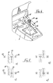
- FIG. 1 schematically shows a selector lever on the center console of a motor vehicle,
- FIG. 2 shows a gear indicator as it appears in FIG. 1 in the front section of the center console, on an enlarged scale,
- FIG. 3 different display options for the gear indicator according to FIG. 2,
- Figure 4 shows a second embodiment with a selector lever which is displaceable in two parallel and one perpendicular to the operating planes and
- Figure 5 shows the gear display according to Figure 4 in different display images.
Nach Figur 1 sitzt ein Wählhebel 1 auf einer Mittelkonsole 2 eines nicht weiter dargestellten Kraftfahrzeuges. Der Wählhebel 1 dient zum Einlegen der einzelnen Fahrstufen eines Kraftfahrzeuggetriebes und weist hierfür, durch eine Manschette 3 nicht einsehbar, an seinem unteren Ende elektrische Kontakte auf. Durch Schließen der Kontakte bei Betätigung des Wählhebels 1 werden Schaltbefehle an eine Auswerteschaltung abgegeben. Die Auswerteschaltung ist nicht Gegenstand der Erfindung und daher nicht gezeichnet und nicht näher erläutert. Es sei nur so viel erwähnt, daß sie ohne weiteres von einem Fachmann aufgebaut werden kann und vorzugsweise einen Mikrocomputer enthält. Ihre Aufgabe ist es, einmal die Stellglieder für das ebenfalls nicht dargestellte Fahrzeuggetriebe anzusteuern. Zum anderen bestimmt sie das Anzeigebild einer Ganganzeige 4.According to Figure 1, a
Der Wählhebel 1 läßt sich in zwei zueinander senkrecht angeordnete Betätigungsebenen verschieben. Es ergeben sich dabei vier Richtungen, die in Figur 1 mit entsprechenden Pfeilen gekennzeichnet sind. Der Betätigungspfeil in Fahrtrichtung trägt dabei die Bezugsziffer 5, der gegen die Fahrtrichtung die Bezugsziffer 6, während die Pfeile nach links und nach rechts mit 7 und 8 bezeichnet sind.The
Die erwähnte Ganganzeige 4 befindet sich ebenfalls auf der Mittelkonsole 2, allerdings in Richtung Armaturenbrett gerückt. Auf diese Weise ist sie vom Fahrer gut einsehbar. Das Anzeigebild der Ganganzeige 4 ist den Bewegungsrichtungen entsprechend der Pfeile 5 bis 7 nachgebildet.The gear indicator 4 mentioned is also located on the
Wie in Figur 2 gut erkennbar, ist sie als Balkenkreuz mit fünf Anzeigefeldern ausgelegt. Das zentrale Anzeigefeld 9 im Mittelpunkt des Balkenkreuzes zeigt die momentan gewählte Gangstufe an. Um dieses zentrale Anzeigefeld 9 gruppieren sich in den Kreuz armen die Anzeigefelder 10, 11, 12 und 13. Sie entsprechen den Betätigungsrichtungen des Wählhebels 1 nach den Pfeilen 5, 6, 7 und 8 und geben die Schaltmöglichkeiten in Bezug auf die gewählte Fahrstufe an.As can be clearly seen in FIG. 2, it is designed as a cross with five display fields. The
Wie das Anzeigefeld 9 nach Figur 2 zeigt, ist in dem dargestellten Fall die Fahrstufe "D" eingelegt. Das heißt, das Getriebe befindet sich im Automatikbetrieb. Die übrigen Anzeigefelder zeigen dem Fahrer an, welche Fahrstufen er nun wählen könnte. Links im Anzeigefeld 12 erscheint "R" für den Rückwärtsgang. Der Fahrer müßte in diesem Fall den Wählhebel 1 in Richtung des Pfeiles 7 drücken. Entsprechendes gilt für die anderen Fahrstufen. Dabei steht "P" für Parkstellung, "N" für Neutral und "M" für manuellen Betrieb.As the
In Figur 3 sind verschiedene Anzeigebilder dargestellt. Die Doppelpfeile sollen anzeigen, daß in die einzelnen Anzeigebilder hin- und zurückgewechselt werden kann. Es ist unter a) wieder das Anzeigebild entsprechend der Figur 2 ersichtlich. Entsprechend dem Doppelpfeil ist es nach oben in das Anzeigebild b) überführbar. Dies bedeutet eine Wählhebelbewegung entsprechend dem Pfeil 5 nach Figur 1.Various display images are shown in FIG. The double arrows are intended to indicate that the individual display images can be switched back and forth. The display image corresponding to FIG. 2 can be seen again under a). According to the double arrow, it can be transferred upwards into the display image b). This means a selector lever movement according to
Sofern der Fahrer den Wählhebel 1 in diese Richtung gedrückt hat, wird die Parkstufe "P" eingelegt und in der Ganganzeige erscheint das Anzeigebild b). In seinem Zentralfeld steht nun "P". Aus dieser Stellung könnte der Fahrer in die Fahrstufen "R", "N" oder - zurück in das Anzeigebild a) - "D" wechseln. Schaltet er nach "R" im Anzeigebild b), erscheint das Anzeigebild d) mit wiederum "R" im Zentralfeld. Im gleichen Maße erscheint das Anzeigebild e), wenn er in die Position "N" wechseit. Die gleichen Anzeigebilder erscheinen aber auch, wenn er die Schaltbewegungen gemäß Anzeigebild a) entsprechend ausführt.If the driver has pressed
Möchte der Fahrer vom Automatikbetrieb in den Handschaltbetrieb überwechseln, so kann er im Anzeigebild a) die untere Position "M" wählen. Dies bedeutet nach Figur 1 demnach eine Schaltbewegung entgegen der Fahrtrichtung in Richtung des Pfeiles 6. Es erscheinen entweder die Anzeigebilder c1), c2) oder f), abhängig vom jeweiligen Fahrzustand das Fahrzeuges. Befindet sich das Fahrzeug im Stillstand oder bewegt sich nur mit geringer Geschwindigkeit z. B. mit weniger als 3 km/h, so erscheint das Bild c1). In diesem Bild ist neben der Möglichkeit des Zürückschaltens in die Fahrstufe "D" auch die Möglichkeit gegeben, den Rückwärtsgang entsprechend "R" einzulegen.If the driver would like to switch from automatic mode to manual mode, he can select the lower position "M" in display image a). According to FIG. 1, this means a switching movement in the direction of
Fährt das Fahrzeug beim Wechseln in das manuelle Schaltprogramm bereits mit einer Geschwindigkeit größer als 3 km/h, erscheint je nach Geschwindigkeit und Motordrehzahl entweder c2) oder bei höherer Geschwindigkeit f). Bei noch höherer Geschwindigkeit können sich je nach Auslegung des Getriebes weitere Schaltbilder für den dritten, vierten und fünften Gang einstellen. In Figur 3 sind sie durch Punkte angedeutet. Die Motordrehzahl und die Geschwindigkeit des Fahrzeuges wird ebenfalls von der Auswerteschaltung berücksichtigt.If the vehicle is already driving at a speed greater than 3 km / h when changing to the manual gearshift program, either c2) or higher f) appears depending on the speed and engine speed. At even higher speeds, depending on the design of the transmission, additional circuit diagrams for third, fourth and fifth gear can be set. In Figure 3 they are indicated by dots. The engine speed and the speed of the vehicle are also taken into account by the evaluation circuit.
Befindet sich das Getriebe nun im Handschaltbetrieb, kann der Fahrer schrittweise die einzelnen Gänge nacheinander hochschalten bzw. runterschalten. In den Anzeigebildern c1), c2) und f) ist deutlich erkennbar, daß jederzeit in den Automatikbetrieb zurückgeschaltet werden kann bzw. der Wählhebel 1 in die Neutralstellung "N" überführbar ist.If the transmission is now in manual mode, the driver can gradually shift up or down the individual gears one after the other. It can be clearly seen in the display images c1), c2) and f) that it is possible to switch back to automatic mode at any time or that the
Wird im manuellen Schaltbetrieb beispielsweise aus dem nicht dargestellten vierten Gang in die Neutralstellung geschaltet, verlangsamt sich das Fahrzeug und entsprechend wechselt die Auswerteschaltung auf der Ganganzeige die entsprechenden Schaltbilder mit abnehmender Geschwindigkeit und ohne Betätigung des Wählhebels 1.If, for example, the manual shift mode shifts from the fourth gear (not shown) to the neutral position, the vehicle slows down and the evaluation circuit on the gear indicator changes the corresponding shift patterns with decreasing speed and without operating the
In Figur 4 ist eine zweite Ausführung der Erfindung dargestellt. Es ist wiederum der Wählhebel 1 auf der Mittelkonsole 2 erkennbar. Im Unterschied zum vorhergehenden Ausführungsbeispiel sind jedoch zwei parallele Betätigungsebenen in Fahrzeuglängsrichtung gegeben. Daraus sind vier Betätigungsrichtungen entsprechend der Pfeile 14 bis 17 möglich. Außerdem ist wieder eine senkrecht dazu stehende Betätigungsebene vorhanden, gekennzeichnet durch die Richtungspfeile 18 und 19. Der Wählhebel 1 ist nach Figur 4 so ausgelegt, daß er bei Betätigungen in Fahrzeuglängsrichtung also vor und zurück jeweils in seine Ausgangslage zurückkehrt. Das gleiche gilt für die Betätigung in Richtung des Pfeiles 19. Der Wählhebel ist jedoch in beiden Betätigungsebenen in Fahrzeuglängsrichtung und ebenso bei einer Betätigung in Richtung des Pfeiles 18 arretiert.FIG. 4 shows a second embodiment of the invention. The
Entsprechend dem vorhergehenden Ausführungsbeispiel befindet sich eine Ganganzeige 20 auf der Konsole 2. In Figur 5 erscheinen die verschiedenen Anzeigebilder dieser Ganganzeige 20. Die Anzeigebilder selbst sind wieder mit a) bis e) bezeichnet.In accordance with the previous exemplary embodiment, there is a
Wie Figur 5 zeigt, besteht die Ganganzeige 20 aus zwei parallel zueinander ausgerichteten Anzeigebänder 21,22 mit der vollständigen Bezeichnung aller möglichen Wählstufen. Dabei ist das linke Anzeigeband 21 dem Bandschaltbetrieb zugeordnet und entspricht den Betätigungsrichtungen der Pfeile 14 und 16. Das rechte Anzeigeband 22 stellt den Automatikbetrieb dar. Ihm sind die Pfeile 15 und 17 zugeordnet. Neben den beiden Anzeigebändern erscheinen auf der Ganganzeige jeweils noch zwei Einzelfelder 23 und 24 für die Wählstufen "N" und "R".As FIG. 5 shows, the
Steht nun der Wählhebel 1 in der Betätigungsebene, die durch die Pfeile 15, 17 repräsentiert wird und ist die Parkstellung eingeschaltet, so erscheint dies auf dem rechten Anzeigeband 22 nach Anzeigebild a) in Figur 5. Der Fahrer hat nun wieder die Möglichkeit entweder nach "R" runterzuschalten, indem er den Wählhebel 1 nach Figur 4 in Richtung des Pfeiles 17 drückt. Er kann aber auch nach rechts entsprechend dem Pfeil 19 in Figur 4 nach "N" ins Feld 24 wechseln. Ebenso kann er die Schaltgasse für den Automatikbetrieb verlassen und in den manuellen Betrieb nach "1" des Anzeigebandes 21 überwechseln. Von dort kann er wiederum in den "R" Bereich entsprechend dem Anzeigefeld 23 weiterschalten.If the
Je nach Wahl erscheinen die unterschiedlichen bilder, von denen lediglich die Bilder b), c) und d) eine Auswahl darstellen. Um beispielsweise in das Bild c) zu gelangen, mußte der Fahrer zunächst einmal in die Fahrstufe "D" schalten, sodann in dieser Fahrstufe den Wagen beschleunigen bis automatisch der vierte Gang im Getriebe eingelegt wird. Sodann könnte er in die Fahrstufe "N" wechseln.Depending on the choice, the different images appear, of which only the images b), c) and d) represent a selection. In order to get into picture c), for example, the driver had to switch to gear "D" first, then accelerate the car in this gear until fourth gear is automatically engaged in the transmission. Then he could switch to gear "N".
Wie das Anzeigebild c) zeigt, haben sich in diesem Fall die Anzeigebalken 21 und 22 verschoben und zwar gegeneinander und gegenüber den feststehenden Anzeigefeldern 23 und 24. Entsprechendes gilt für die Anzeigebilder c) und d). Um dieses Verschieben der Anzeigebalken zu realisieren, ist die Ganganzeige 20 als Bildschirm ausgelegt, der von der Auswertelektronik angesteuert wird.As the display image c) shows, the display bars 21 and 22 have shifted in this case, namely against each other and with respect to the fixed display fields 23 and 24. The same applies to the display images c) and d). In order to implement this shifting of the display bar, the
Zusammenfassend läßt sich für dieses Ausführungsbeispiel wiederum sagen, daß das Anzeigebild den Betätigungsrichtungen des Wählhebels 1 entspricht und für den Fahrer weitgehend selbsterklärend ist. Er kann in dem jeweiligen Anzeigebild eindeutig erkennen, in welche Richtungen er den Wählhebel 1 bewegen muß, um die gewünschte Fahrstufe zu erhalten.In summary, it can be said for this exemplary embodiment that the display image corresponds to the actuation directions of the
Es liegt auf der Band, daß die Ganganzeige an jedem geeigneten Ort im Fahrzeug vorgesehen sein kann, so zum Beispiel auch als weiteres Instrument im Armaturenbrett. Das gleiche gilt für den Schalthebel.It is on the band that the gear indicator can be provided at any suitable location in the vehicle, for example as a further instrument in the dashboard. The same applies to the gear lever.
Claims (8)
Applications Claiming Priority (2)
| Application Number | Priority Date | Filing Date | Title |
|---|---|---|---|
| DE3929268 | 1989-09-02 | ||
| DE3929268A DE3929268A1 (en) | 1989-09-02 | 1989-09-02 | MOTOR VEHICLE TRANSMISSION |
Publications (2)
| Publication Number | Publication Date |
|---|---|
| EP0416227A1 true EP0416227A1 (en) | 1991-03-13 |
| EP0416227B1 EP0416227B1 (en) | 1992-12-16 |
Family
ID=6388555
Family Applications (1)
| Application Number | Title | Priority Date | Filing Date |
|---|---|---|---|
| EP19900111928 Expired - Lifetime EP0416227B1 (en) | 1989-09-02 | 1990-06-23 | Motor vehicle transmission |
Country Status (2)
| Country | Link |
|---|---|
| EP (1) | EP0416227B1 (en) |
| DE (2) | DE3929268A1 (en) |
Cited By (9)
| Publication number | Priority date | Publication date | Assignee | Title |
|---|---|---|---|---|
| FR2807716A1 (en) * | 2000-04-17 | 2001-10-19 | Peugeot Citroen Automobiles Sa | Driver's control lever, for automobile transmission, has step-by-step gear ratio control, in fore-and-aft slot, and automatic neutral and reverse positions in transverse slot |
| EP1146257A3 (en) * | 2000-04-14 | 2004-01-28 | Siemens Aktiengesellschaft | Device for selection of a transmission range or gear for an automotive vehicle transmission |
| WO2003102449A3 (en) * | 2002-05-28 | 2004-02-19 | Zf Lemfoerder Metallwaren Ag | Optical display device pertaining to a selector-lever arrangement |
| DE102004024327A1 (en) * | 2004-05-15 | 2005-12-01 | Wolfgang Dr. Mergenthaler | Algorithm to operate a number of industrial welding robots within a single cell |
| DE102005062298A1 (en) * | 2005-12-24 | 2007-06-28 | Dr.Ing.H.C. F. Porsche Ag | Switching device for a transmission |
| WO2010112932A1 (en) | 2009-04-03 | 2010-10-07 | Bentley Motors Limited | Selector |
| EP1486703A3 (en) * | 2003-06-10 | 2011-04-27 | Honda Motor Co., Ltd. | Apparatus for generating tactile force for a vehicle |
| WO2015009826A3 (en) * | 2013-07-18 | 2015-03-19 | Chrysler Group Llc | Lever style electronic shifter with concealed lever position |
| WO2020109385A1 (en) * | 2018-11-30 | 2020-06-04 | Zf Friedrichshafen Ag | Device for selecting an operating mode of a motor vehicle |
Families Citing this family (16)
| Publication number | Priority date | Publication date | Assignee | Title |
|---|---|---|---|---|
| DE4228982C1 (en) * | 1992-08-31 | 1993-09-02 | Lemfoerder Metallwaren Ag, 49448 Lemfoerde, De | |
| DE4233938A1 (en) * | 1992-10-08 | 1994-04-14 | Bayerische Motoren Werke Ag | Selector switch unit for electronic control of automatic gearbox - has steering column selector lever able to move in two planes at right angles giving normal, automatic or restricted operating modes |
| DE4305903A1 (en) * | 1993-02-26 | 1994-09-01 | Bayerische Motoren Werke Ag | Gearshift device for a motor vehicle automatic transmission |
| DE19529207C2 (en) * | 1995-08-09 | 2001-04-26 | Zf Lemfoerder Metallwaren Ag | Switch position indicator |
| DE19714495A1 (en) * | 1997-04-08 | 1998-10-15 | Bayerische Motoren Werke Ag | Dialing device with a display device |
| DE19725231B4 (en) * | 1997-06-14 | 2008-11-13 | Volkswagen Ag | Transmission gear indicator |
| DE19804640B4 (en) * | 1998-02-06 | 2007-11-22 | Bayerische Motoren Werke Ag | Motor vehicle with an electronically controlled automatic transmission |
| DE19828039B4 (en) * | 1998-06-24 | 2006-10-12 | Siemens Ag | operating device |
| DE19850685A1 (en) | 1998-11-03 | 2000-05-04 | Bayerische Motoren Werke Ag | Selector device for an automatic transmission of a motor vehicle |
| DE10105491B4 (en) * | 2001-02-07 | 2010-05-12 | Jopp Gmbh | Switching device for a transmission |
| JP3792586B2 (en) * | 2002-03-12 | 2006-07-05 | 本田技研工業株式会社 | Vehicle shift operation device |
| DE102004047102B3 (en) * | 2004-09-29 | 2006-03-09 | Bayerische Motoren Werke Ag | Motor vehicle parking brake system, with an automatic gearbox, coordinates the working of the independent gearbox and wheel brakes so that the gearbox brake is always activated to block the gearbox output shaft |
| DE102005046278B4 (en) * | 2004-09-29 | 2008-04-03 | Bayerische Motoren Werke Ag | Motor vehicle with an electronically controllable parking brake and with an electronically controllable parking brake |
| DE102004047100B3 (en) * | 2004-09-29 | 2006-03-02 | Bayerische Motoren Werke Ag | Parking lock and parking brake for vehicle has electronic control unit which can activate parking brake before parking lock when lock activation condition occurs |
| DE202010007515U1 (en) | 2010-06-02 | 2010-09-02 | Leopold Kostal Gmbh & Co. Kg | Device for actuating a parking lock of an automatically operated transmission of a motor vehicle |
| DE102011010705A1 (en) | 2011-02-09 | 2012-08-16 | Gm Global Technology Operations, Llc | Passenger car without B-pillar |
Citations (8)
| Publication number | Priority date | Publication date | Assignee | Title |
|---|---|---|---|---|
| DE1964524A1 (en) * | 1968-12-31 | 1970-07-16 | Citroen Sa | Electronic control device for a gearbox with graduated transmission ratios |
| US3985095A (en) * | 1975-01-09 | 1976-10-12 | General Motors Corporation | Gear shift indicator |
| DE3237517A1 (en) * | 1982-10-09 | 1984-04-12 | Wabco Westinghouse Fahrzeugbremsen GmbH, 3000 Hannover | SHIFT INDICATOR FOR A GEAR SHIFT |
| DE3237509A1 (en) * | 1982-10-09 | 1984-04-12 | Wabco Westinghouse Fahrzeugbremsen GmbH, 3000 Hannover | GEAR SHIFT FOR A FOREIGN ACTUATED GEARBOX |
| DE3337930A1 (en) * | 1982-12-23 | 1984-07-05 | Zahnradfabrik Friedrichshafen Ag, 7990 Friedrichshafen | Selector switch in a shift control for automatic gearboxes |
| DE3422262A1 (en) * | 1984-06-15 | 1985-12-19 | Audi AG, 8070 Ingolstadt | Shift device for an automatic transmission |
| FR2600285A1 (en) * | 1986-06-20 | 1987-12-24 | Renault | AUTOMATIC GEARBOX ELECTROMECHANICAL CONTROL DEVICE |
| DE3717675A1 (en) * | 1987-05-26 | 1988-12-08 | Bayerische Motoren Werke Ag | Motor vehicle with automatic transmission |
Family Cites Families (8)
| Publication number | Priority date | Publication date | Assignee | Title |
|---|---|---|---|---|
| DE734540C (en) * | 1937-05-15 | 1943-04-19 | Engrenages De Prec Procedes Ma | Switching device for electromagnetic motor vehicle change gear |
| DE721350C (en) * | 1939-04-29 | 1942-06-06 | Miag Muehlenbau Und Ind Ag | Automatic circuit for gear change or continuously variable transmissions of motor vehicles or the like. |
| DE812999C (en) * | 1950-05-13 | 1951-09-06 | Eugen Bauckhage | Display device for the gear engaged in motor vehicles |
| DE891661C (en) * | 1951-12-14 | 1953-10-01 | Daimler Benz Ag | Speed indicator for motor vehicles |
| US2964964A (en) * | 1959-04-10 | 1960-12-20 | Gen Motors Corp | Control mechanism |
| DE1929359U (en) * | 1965-07-03 | 1965-12-16 | Franz Walter Wissmann | MOTOR VEHICLE WITH GEAR SHIFT. |
| DE2507086A1 (en) * | 1975-02-19 | 1976-08-26 | Daimler Benz Ag | GEAR DISPLAY FOR MOTOR VEHICLES |
| DE3807881A1 (en) * | 1988-03-10 | 1989-09-21 | Porsche Ag | SWITCHING DEVICE FOR AN AUTOMATIC TRANSMISSION OF A MOTOR VEHICLE |
-
1989
- 1989-09-02 DE DE3929268A patent/DE3929268A1/en not_active Withdrawn
-
1990
- 1990-06-23 DE DE9090111928T patent/DE59000604D1/en not_active Expired - Fee Related
- 1990-06-23 EP EP19900111928 patent/EP0416227B1/en not_active Expired - Lifetime
Patent Citations (8)
| Publication number | Priority date | Publication date | Assignee | Title |
|---|---|---|---|---|
| DE1964524A1 (en) * | 1968-12-31 | 1970-07-16 | Citroen Sa | Electronic control device for a gearbox with graduated transmission ratios |
| US3985095A (en) * | 1975-01-09 | 1976-10-12 | General Motors Corporation | Gear shift indicator |
| DE3237517A1 (en) * | 1982-10-09 | 1984-04-12 | Wabco Westinghouse Fahrzeugbremsen GmbH, 3000 Hannover | SHIFT INDICATOR FOR A GEAR SHIFT |
| DE3237509A1 (en) * | 1982-10-09 | 1984-04-12 | Wabco Westinghouse Fahrzeugbremsen GmbH, 3000 Hannover | GEAR SHIFT FOR A FOREIGN ACTUATED GEARBOX |
| DE3337930A1 (en) * | 1982-12-23 | 1984-07-05 | Zahnradfabrik Friedrichshafen Ag, 7990 Friedrichshafen | Selector switch in a shift control for automatic gearboxes |
| DE3422262A1 (en) * | 1984-06-15 | 1985-12-19 | Audi AG, 8070 Ingolstadt | Shift device for an automatic transmission |
| FR2600285A1 (en) * | 1986-06-20 | 1987-12-24 | Renault | AUTOMATIC GEARBOX ELECTROMECHANICAL CONTROL DEVICE |
| DE3717675A1 (en) * | 1987-05-26 | 1988-12-08 | Bayerische Motoren Werke Ag | Motor vehicle with automatic transmission |
Cited By (14)
| Publication number | Priority date | Publication date | Assignee | Title |
|---|---|---|---|---|
| EP1146257A3 (en) * | 2000-04-14 | 2004-01-28 | Siemens Aktiengesellschaft | Device for selection of a transmission range or gear for an automotive vehicle transmission |
| FR2807716A1 (en) * | 2000-04-17 | 2001-10-19 | Peugeot Citroen Automobiles Sa | Driver's control lever, for automobile transmission, has step-by-step gear ratio control, in fore-and-aft slot, and automatic neutral and reverse positions in transverse slot |
| WO2003102449A3 (en) * | 2002-05-28 | 2004-02-19 | Zf Lemfoerder Metallwaren Ag | Optical display device pertaining to a selector-lever arrangement |
| US7167085B2 (en) | 2002-05-28 | 2007-01-23 | ZF Lemförder Metallwaren AG | Optical display device for a selector lever arrangement |
| EP1486703A3 (en) * | 2003-06-10 | 2011-04-27 | Honda Motor Co., Ltd. | Apparatus for generating tactile force for a vehicle |
| EP2390535A1 (en) * | 2003-06-10 | 2011-11-30 | Honda Motor Co., Ltd. | Apparatus for generating tactile force for a vehicle |
| DE102004024327A1 (en) * | 2004-05-15 | 2005-12-01 | Wolfgang Dr. Mergenthaler | Algorithm to operate a number of industrial welding robots within a single cell |
| US7878087B2 (en) | 2005-12-24 | 2011-02-01 | Dr Ing. H.C. F. Porsche Aktiengesellschaft | Selector device for a transmission |
| EP1801463A3 (en) * | 2005-12-24 | 2008-06-18 | Dr. Ing. h.c. F. Porsche Aktiengesellschaft | Changing device for a transmission |
| DE102005062298A1 (en) * | 2005-12-24 | 2007-06-28 | Dr.Ing.H.C. F. Porsche Ag | Switching device for a transmission |
| WO2010112932A1 (en) | 2009-04-03 | 2010-10-07 | Bentley Motors Limited | Selector |
| CN102365478A (en) * | 2009-04-03 | 2012-02-29 | 英国宾利汽车有限公司 | Selector |
| WO2015009826A3 (en) * | 2013-07-18 | 2015-03-19 | Chrysler Group Llc | Lever style electronic shifter with concealed lever position |
| WO2020109385A1 (en) * | 2018-11-30 | 2020-06-04 | Zf Friedrichshafen Ag | Device for selecting an operating mode of a motor vehicle |
Also Published As
| Publication number | Publication date |
|---|---|
| DE3929268A1 (en) | 1991-03-07 |
| DE59000604D1 (en) | 1993-01-28 |
| EP0416227B1 (en) | 1992-12-16 |
Similar Documents
| Publication | Publication Date | Title |
|---|---|---|
| EP0416227B1 (en) | Motor vehicle transmission | |
| EP0870955B1 (en) | Shift selector with a position signalling device | |
| DE10206985B4 (en) | Transmission shifter | |
| EP1045172B1 (en) | Control device for an automatic transmission of a motor vehicle | |
| DE19706625B4 (en) | Speed control device for an automatic transmission | |
| DE4005588C2 (en) | Switching device for an automatic transmission | |
| DE3717675C5 (en) | Switching device for a motor vehicle with automatic transmission | |
| DE3832971C2 (en) | ||
| EP0108209A2 (en) | Gear shifting for a power assisted transmission | |
| EP0999383A2 (en) | Gear-shift device for an automatic gearbox of a motor vehicle | |
| EP1432934B1 (en) | Signal transmitter for setting the operating states of an automatic shifting device | |
| DE102012215659A1 (en) | Electronic gearshift with adaptive position | |
| EP0106789B1 (en) | Gear change indicator | |
| DE102005048875B4 (en) | Switching unit for an electronically shifted transmission of a motor vehicle | |
| DE3337930C2 (en) | Selector switch in a shift control for automatic transmissions | |
| DE3924318A1 (en) | Motor vehicle gear change with separate actuating levers - including one of steering column which overrides floor-mounted counterpart e.g. for overtaking or economy driving | |
| DE19849076A1 (en) | Selector for automatically changed vehicle gearbox moves selection lever from selection gate for stepwise gear changing in manual mode into preselecting gate when engine is turned off | |
| DE3939030A1 (en) | Selection position indicator for switching or selection gear lever - has large area digital display element in gear knob showing single symbol | |
| EP1081414B1 (en) | Selector mechanism for controlling an automatic transmission of a motor vehicle | |
| DE10105491B4 (en) | Switching device for a transmission | |
| EP0725233A2 (en) | Ratio selector apparatus for gearbox | |
| EP0798493B1 (en) | Gear shift device | |
| DE19609585A1 (en) | Method to control continuous gearing, especially on motor vehicle | |
| EP4038295B1 (en) | Gearbox system and method for operating said type of gearbox system | |
| DE10000338A1 (en) | Arrangement for determining gear engaged in motor vehicle has sensor element on gear lever detectable by touch and moved into detectable position when/after selecting defined gear |
Legal Events
| Date | Code | Title | Description |
|---|---|---|---|
| PUAI | Public reference made under article 153(3) epc to a published international application that has entered the european phase |
Free format text: ORIGINAL CODE: 0009012 |
|
| 17P | Request for examination filed |
Effective date: 19901221 |
|
| AK | Designated contracting states |
Kind code of ref document: A1 Designated state(s): DE FR GB IT |
|
| 17Q | First examination report despatched |
Effective date: 19920309 |
|
| GRAA | (expected) grant |
Free format text: ORIGINAL CODE: 0009210 |
|
| AK | Designated contracting states |
Kind code of ref document: B1 Designated state(s): DE FR GB IT |
|
| GBT | Gb: translation of ep patent filed (gb section 77(6)(a)/1977) |
Effective date: 19921217 |
|
| REF | Corresponds to: |
Ref document number: 59000604 Country of ref document: DE Date of ref document: 19930128 |
|
| ITF | It: translation for a ep patent filed |
Owner name: STUDIO JAUMANN |
|
| ET | Fr: translation filed | ||
| RAP4 | Party data changed (patent owner data changed or rights of a patent transferred) |
Owner name: BAYERISCHE MOTOREN WERKE AKTIENGESELLSCHAFT |
|
| PLBE | No opposition filed within time limit |
Free format text: ORIGINAL CODE: 0009261 |
|
| STAA | Information on the status of an ep patent application or granted ep patent |
Free format text: STATUS: NO OPPOSITION FILED WITHIN TIME LIMIT |
|
| 26N | No opposition filed | ||
| PGFP | Annual fee paid to national office [announced via postgrant information from national office to epo] |
Ref country code: DE Payment date: 19950526 Year of fee payment: 6 |
|
| PGFP | Annual fee paid to national office [announced via postgrant information from national office to epo] |
Ref country code: GB Payment date: 19950622 Year of fee payment: 6 |
|
| PGFP | Annual fee paid to national office [announced via postgrant information from national office to epo] |
Ref country code: FR Payment date: 19950630 Year of fee payment: 6 |
|
| PG25 | Lapsed in a contracting state [announced via postgrant information from national office to epo] |
Ref country code: GB Effective date: 19960623 |
|
| GBPC | Gb: european patent ceased through non-payment of renewal fee |
Effective date: 19960623 |
|
| PG25 | Lapsed in a contracting state [announced via postgrant information from national office to epo] |
Ref country code: FR Effective date: 19970228 |
|
| PG25 | Lapsed in a contracting state [announced via postgrant information from national office to epo] |
Ref country code: DE Effective date: 19970301 |
|
| REG | Reference to a national code |
Ref country code: FR Ref legal event code: ST |
|
| PG25 | Lapsed in a contracting state [announced via postgrant information from national office to epo] |
Ref country code: IT Free format text: LAPSE BECAUSE OF NON-PAYMENT OF DUE FEES;WARNING: LAPSES OF ITALIAN PATENTS WITH EFFECTIVE DATE BEFORE 2007 MAY HAVE OCCURRED AT ANY TIME BEFORE 2007. THE CORRECT EFFECTIVE DATE MAY BE DIFFERENT FROM THE ONE RECORDED. Effective date: 20050623 |