EP0409708A1 - Plattenkokille für Metallstranggiessen - Google Patents
Plattenkokille für Metallstranggiessen Download PDFInfo
- Publication number
- EP0409708A1 EP0409708A1 EP90402033A EP90402033A EP0409708A1 EP 0409708 A1 EP0409708 A1 EP 0409708A1 EP 90402033 A EP90402033 A EP 90402033A EP 90402033 A EP90402033 A EP 90402033A EP 0409708 A1 EP0409708 A1 EP 0409708A1
- Authority
- EP
- European Patent Office
- Prior art keywords
- plates
- cavity
- plate
- mold according
- pair
- Prior art date
- Legal status (The legal status is an assumption and is not a legal conclusion. Google has not performed a legal analysis and makes no representation as to the accuracy of the status listed.)
- Granted
Links
- 238000009749 continuous casting Methods 0.000 title claims abstract description 7
- 239000002184 metal Substances 0.000 title claims abstract description 7
- 229910052751 metal Inorganic materials 0.000 title claims abstract description 7
- 230000003042 antagnostic effect Effects 0.000 claims description 3
- 230000000284 resting effect Effects 0.000 claims 1
- 230000007547 defect Effects 0.000 description 6
- 238000005096 rolling process Methods 0.000 description 6
- 229910000831 Steel Inorganic materials 0.000 description 5
- 239000010959 steel Substances 0.000 description 5
- 238000005452 bending Methods 0.000 description 3
- 238000005266 casting Methods 0.000 description 2
- 230000000694 effects Effects 0.000 description 2
- 238000000605 extraction Methods 0.000 description 2
- 239000000463 material Substances 0.000 description 2
- 230000003014 reinforcing effect Effects 0.000 description 2
- RYGMFSIKBFXOCR-UHFFFAOYSA-N Copper Chemical compound [Cu] RYGMFSIKBFXOCR-UHFFFAOYSA-N 0.000 description 1
- 229910000881 Cu alloy Inorganic materials 0.000 description 1
- 208000029152 Small face Diseases 0.000 description 1
- 230000015572 biosynthetic process Effects 0.000 description 1
- 239000002826 coolant Substances 0.000 description 1
- 229910052802 copper Inorganic materials 0.000 description 1
- 239000010949 copper Substances 0.000 description 1
- 230000008034 disappearance Effects 0.000 description 1
- 238000006073 displacement reaction Methods 0.000 description 1
- 230000008030 elimination Effects 0.000 description 1
- 238000003379 elimination reaction Methods 0.000 description 1
- 238000002360 preparation method Methods 0.000 description 1
- 230000002787 reinforcement Effects 0.000 description 1
- 125000006850 spacer group Chemical group 0.000 description 1
- XLYOFNOQVPJJNP-UHFFFAOYSA-N water Substances O XLYOFNOQVPJJNP-UHFFFAOYSA-N 0.000 description 1
Images

Classifications
-
- B—PERFORMING OPERATIONS; TRANSPORTING
- B22—CASTING; POWDER METALLURGY
- B22D—CASTING OF METALS; CASTING OF OTHER SUBSTANCES BY THE SAME PROCESSES OR DEVICES
- B22D11/00—Continuous casting of metals, i.e. casting in indefinite lengths
- B22D11/04—Continuous casting of metals, i.e. casting in indefinite lengths into open-ended moulds
Definitions
- the present invention relates to an ingot mold with plates for the continuous casting of metal, in particular steel.
- molds comprising four cooled plates which delimit between them a cavity for the formation of a cast slab of a fixed fixed section.
- This cavity is rectilinear in the direction of extraction of the slab and generally has a roughly rectangular cross section.
- the plates forming two opposite walls of the mold cavity are applied against bearing faces formed on the other plates constituting the other two opposite walls of said mold cavity. These bearing faces constitute at the same time joint faces between the plates, in the sense that they extend to the cavity of the mold and thus define joints between the internal faces of the plates.
- the plates of this mold are generally clamped against each other by clamping devices acting roughly perpendicular to the bearing faces.
- the slabs cast in this type of ingot mold are then subjected to rolling to obtain sheets.
- sheets from slabs thick about 300 mm undergo a strong cross-cutting because a slab of about 1700 mm wide is transformed into a sheet having a width of about 4500 mm.
- a metal reserve that is to say an exceptional additional width of approximately 80 mm. This additional width is a significant loss of material.
- One solution to avoid this folding defect consists, for example, in eliminating the corners of the slab by making, at each corner, a chamfer by torch.
- Another solution consists in directly casting chamfered slabs at the angles using molds comprising four cooled plates delimiting a cavity whose angles are cut by chamfers.
- the present invention relates to an ingot mold with plates for the continuous casting of metal, in particular of slabs, comprising four cooled plates delimiting between them a cavity whose angles are cut by chamfers and in which the plates of each pair of opposite plates are supported on corresponding bearing faces of the plates of the other pair of opposite plates, the plates being intended to be clamped against each other the others by clamping devices acting roughly perpendicular to the bearing faces, characterized in that the chamfer of each angle of the cavity is formed by hypotenuse of a right triangle whose sides of the right angle are each located in a plane formed by an internal wall of one of the adjacent plates and have a length greater than 30mm.
- the sides of the right angle of the right triangle have a length of between 30 and 150mm, depending on the size of the slabs and the grade of steel to be cast.
- the sides of the right angle of the right triangle are respectively 80 mm and 50 mm for slabs 300 mm thick
- the bearing faces between the adjacent plates are inclined towards the inside of the mold at an angle of between 5 and 7 °
- the chamfer of each angle of the cavity is formed on the pair of plates constituting the small walls of said cavity
- - the long side of each right triangle is located in a plane formed by each large wall of the cavity
- - the plates constituting the small walls of the cavity comprise, opposite each bearing face on the adjacent plate, a shoe bearing on a side face of an extension of said adjacent plate and long enough to take up the forces of bending due to hot shrinkage
- - each skate has a deviating area of the lateral face of the extension of the adjacent plate and a thinned zone exerting an antagonistic force with the heat of withdrawal.
- the plate clamping devices are constituted by jacks comprising means for adjusting the force and for maintaining the clamping
- the means for adjusting the force and for maintaining the tightening are constituted
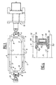
- the mold 1 for the continuous casting of steel comprises two large opposite plates 2 and two small opposite plates 3 which delimit between them a rectilinear cavity 4 in the direction of extraction of the slab and of cross section roughly rectangular.
- the plates 2 and 3 made of copper or a copper alloy, are fixed on reinforcing plates of steel respectively 5 and 6 and are provided with grooves 7 provided for the passage of an appropriate cooling agent such as water. .
- the small plates 3 are supported on corresponding support faces 8 of the two large plates 2.
- the plates 2 and 3 are clamped against each other by clamping devices 10 which act on each small plate 3 via the corresponding reinforcement plates 6 in a direction roughly perpendicular to the faces d 'support 8.
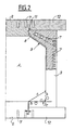
- the angles of the cavity 4 are cut by chamfers 9.
- chamfers 9 are produced on the pair of small plates 3 and, as can be seen in FIG. 2, they are each formed by the hypotenuse "c" of a right triangle T whose sides "a" and “b” of the right angle have a length greater than 30mm and preferably between 30 and 150mm.
- the side “a” has a length equal to 80mm and the side “b” has a length equal to 50mm.
- each right triangle T is located in the plane of the internal wall of the large adjacent plate 2 and the "b" side is located in the plane of the internal wall of the small plate 3 on which the corresponding chamfer 9.
- the small plates 3 are connected to the large plates 2 by bearing faces 8 which are inclined towards the inside of the mold 1 at an angle of between 5 and 7 °.
- each longitudinal wall of the large plates 2 comprises, on the one hand, a draft 11 whose edge is also inclined towards the inside of the ingot mold at an angle between 5 and 7 ° and, on the other hand, an extension 12 which forms, with said draft 11, an embedding by song at an angle for the adjacent small plate 3.
- This embedding makes it possible to substantially improve the seal between the plates 2 and 3 of the mold.
- the folding is all the more important as the thickness of the slab is high.
- FIGS. 3A to 3D The folding defects of the edges of the sheets obtained after rolling the slab were compared and shown in FIGS. 3A to 3D.
- Figs. 3A, 3B, 3C and 3D represent the cut images respectively at the level of the head, the middle, and the foot, of a bank of laminated sheet obtained after rolling slabs having chamfers of respective dimensions expressed in mm: 30 X 20; 50 X 65; 60 X 65; 80 X 50.
- a sheet made from a 300 mm thick slab without chamfer, not shown in the figures has a fold of about 40 mm with an average loss of material of 80 mm.
- the folding effect is no more than about 3 mm and does not disturb more than 15 mm of edge (3B and 3C).
- each small plate 30 of the mold 1 comprises, opposite the bearing faces 8, a shoe 31 which rests on the side face of the extension 12 of each large adjacent plate 2.
- the shoe 31 is long enough to take up the bending forces due to the withdrawal heat.
- each shoe 31 may include a zone 32 which is not in contact with the lateral face of the extension 12 and a thinned section 33 which creates a lever arm exerting an antagonistic force in the heat of withdrawal.
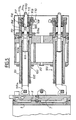
- FIG. 5 we will describe the clamping device 10.
- a clamping device which exerts a force on a small plate, the clamping device exerting a force on the opposite small plate being identical.
- the clamping device 10 comprises two jacks 100 superimposed in a vertical plane.
- the jacks 100 of each group of jacks are joined together by a spacer 20.
- Each jack 100 comprises a cylinder 101 in which a hollow rod 102 is slidably mounted, one end 102a of which is secured to the reinforcing plate 6 of the corresponding small plate 3.
- an operating rod 103 which passes through a housing 104 fixed on the end of the cylinder 101.
- the operating rod 103 comprises a shoulder 103a which provides, with the housing 104 and the body of said operating rod 103, an internal chamber 105 closed by a piston 106 slidably mounted on the body of the rod 103 and inside the housing 104 .
- the end of the housing 104 is fixed a cap 107 providing with the piston 106 a small internal chamber 108 into which opens a small pipe 109 which can be connected by a connector 110 to a pump not shown.
- the cap 107 has an internal threaded bore 107a into which a screw 111 is screwed.
- This screw 111 also has an internal bore 111a allowing the body of the rod 103 to pass through said screw.
- the end 111b of the screw 111 is in contact with the piston 106.
- the clamping operation of the plates 2 and 3 of the mold 1 is carried out as follows.
- the large plates 2 are tightened to come into contact effortlessly on the small plates 3, then the small plates are tightened by action on the operating screw 103 which has a hexagon 103b for this purpose, so that the bearing faces 8 of the small plates 3 and of the large plates 2 come in touch.
- This operation is carried out by successive bearing between the operating rod 103 of the upper cylinder and the lower cylinder.
- the small chamber 108 is put under pressure which has the effect of displacing the piston 106, compressing the elastic washers 112 and exerting a determined force on the small plate 3 by through the rod 102.
- the screw 111 is turned so that its end 111b comes into contact with the piston 106, which makes it possible to disconnect the pump.
- the ingot mold with plates according to the invention makes it possible, thanks in particular to the dimensional characteristics of the angle grooves of the cavity, the total elimination of the folding defect at the edge of the sheet and this without any impact on the quality of the product obtained.
Landscapes
- Engineering & Computer Science (AREA)
- Mechanical Engineering (AREA)
- Continuous Casting (AREA)
Priority Applications (1)
| Application Number | Priority Date | Filing Date | Title |
|---|---|---|---|
| AT90402033T ATE96705T1 (de) | 1989-07-19 | 1990-07-13 | Plattenkokille fuer metallstranggiessen. |
Applications Claiming Priority (2)
| Application Number | Priority Date | Filing Date | Title |
|---|---|---|---|
| FR8909731 | 1989-07-19 | ||
| FR898909731A FR2649918B1 (fr) | 1989-07-19 | 1989-07-19 | Lingotiere a plaques pour la coulee continue de metal |
Publications (2)
| Publication Number | Publication Date |
|---|---|
| EP0409708A1 true EP0409708A1 (de) | 1991-01-23 |
| EP0409708B1 EP0409708B1 (de) | 1993-11-03 |
Family
ID=9383935
Family Applications (1)
| Application Number | Title | Priority Date | Filing Date |
|---|---|---|---|
| EP90402033A Expired - Lifetime EP0409708B1 (de) | 1989-07-19 | 1990-07-13 | Plattenkokille für Metallstranggiessen |
Country Status (7)
| Country | Link |
|---|---|
| US (1) | US5191924A (de) |
| EP (1) | EP0409708B1 (de) |
| JP (1) | JP3001063B2 (de) |
| AT (1) | ATE96705T1 (de) |
| DE (1) | DE69004367T2 (de) |
| ES (1) | ES2048459T3 (de) |
| FR (1) | FR2649918B1 (de) |
Cited By (1)
| Publication number | Priority date | Publication date | Assignee | Title |
|---|---|---|---|---|
| WO2013100499A1 (ko) | 2011-12-27 | 2013-07-04 | 주식회사 포스코 | 연속주조 주형 |
Families Citing this family (9)
| Publication number | Priority date | Publication date | Assignee | Title |
|---|---|---|---|---|
| CN2776595Y (zh) * | 2005-03-07 | 2006-05-03 | 鞍钢集团新钢铁有限责任公司 | 一种板坯连铸用的异形结晶器 |
| CN1840252A (zh) * | 2005-03-28 | 2006-10-04 | 鞍钢集团新钢铁有限责任公司 | 中厚板坯连铸连轧板卷的生产工艺 |
| RU2323062C1 (ru) * | 2006-07-04 | 2008-04-27 | ООО "Корад" | Кристаллизатор для непрерывного литья слябов |
| RU2340425C2 (ru) * | 2006-09-25 | 2008-12-10 | Открытое акционерное общество "Магнитогорский металлургический комбинат" | Кристаллизатор для непрерывной разливки стали |
| DE102007054911B4 (de) * | 2007-11-15 | 2015-02-05 | Thyssenkrupp Steel Europe Ag | Breitenverstellbare Kokille und Verfahren zur Herstellung eines Warmbandes |
| US20110308760A1 (en) * | 2009-02-09 | 2011-12-22 | Hisamune Tanaka | Apparatus for production of metallic slab using electron beam, and process for production of metallic slab using the apparatus |
| DE102012108952A1 (de) | 2012-09-21 | 2014-05-15 | Voestalpine Stahl Gmbh | Vorrichtung zum Stranggießen von Metallen |
| JP6085571B2 (ja) * | 2014-01-06 | 2017-02-22 | 三島光産株式会社 | 連続鋳造用鋳型 |
| CN110405163B (zh) * | 2019-09-03 | 2023-05-23 | 山东钢铁股份有限公司 | 一种消除大宽度钢板轧材边部黑线缺陷的设备及方法 |
Citations (4)
| Publication number | Priority date | Publication date | Assignee | Title |
|---|---|---|---|---|
| US3237252A (en) * | 1963-10-01 | 1966-03-01 | Babcock & Wilcox Co | Mold clamping devices |
| FR2289270A1 (fr) * | 1974-11-04 | 1976-05-28 | Concast Ag | Lingotiere a plaques pour la coulee continue de metal et en particulier d'acier |
| FR2436636A1 (fr) * | 1978-09-21 | 1980-04-18 | Fives Cail Babcock | Dispositif pour le reglage de l'une des deux plaques frontales d'une lingotiere de coulee continue |
| FR2584322A1 (fr) * | 1985-07-04 | 1987-01-09 | Fives Cail Babcock | Dispositif d'assemblage des cotes d'une lingotiere de coulee continue |
Family Cites Families (7)
| Publication number | Priority date | Publication date | Assignee | Title |
|---|---|---|---|---|
| SU850280A1 (ru) * | 1979-04-04 | 1981-08-03 | Центральный Ордена Трудового Красногознамени Научно-Исследовательский Ин-Ститут Черной Металлургии Им.И.П.Бардина | Кристаллизатор дл установок непре-РыВНОй РАзлиВКи МЕТАллОВ |
| SU923727A1 (ru) * | 1979-06-22 | 1982-04-30 | Sergej P Bakumenko | Кристаллизатор для формирования слитка i |
| LU81982A1 (de) * | 1979-12-11 | 1981-07-23 | Arbed | Zum bogenstranggiessen von mehreck-stahlprofilen geeignete stranggiesskokillen sowie verfahren zur nachbearbeitung ihrer innenflaechen |
| JPS5731444A (en) * | 1980-07-31 | 1982-02-19 | Mitsubishi Heavy Ind Ltd | Mold for continuous casting machine |
| JPS5747557A (en) * | 1980-09-06 | 1982-03-18 | Daido Steel Co Ltd | Mold for continuous casting |
| CH664915A5 (de) * | 1984-10-26 | 1988-04-15 | Concast Service Union Ag | Durchlaufkokille zum stranggiessen von stahlstraengen mit polygonalem querschnitt. |
| US4947925A (en) * | 1989-02-24 | 1990-08-14 | Wagstaff Engineering, Inc. | Means and technique for forming the cavity of an open-ended mold |
-
1989
- 1989-07-19 FR FR898909731A patent/FR2649918B1/fr not_active Expired - Fee Related
-
1990
- 1990-07-13 EP EP90402033A patent/EP0409708B1/de not_active Expired - Lifetime
- 1990-07-13 ES ES90402033T patent/ES2048459T3/es not_active Expired - Lifetime
- 1990-07-13 AT AT90402033T patent/ATE96705T1/de not_active IP Right Cessation
- 1990-07-13 DE DE90402033T patent/DE69004367T2/de not_active Expired - Lifetime
- 1990-07-18 US US07/554,704 patent/US5191924A/en not_active Expired - Lifetime
- 1990-07-19 JP JP2191846A patent/JP3001063B2/ja not_active Expired - Lifetime
Patent Citations (4)
| Publication number | Priority date | Publication date | Assignee | Title |
|---|---|---|---|---|
| US3237252A (en) * | 1963-10-01 | 1966-03-01 | Babcock & Wilcox Co | Mold clamping devices |
| FR2289270A1 (fr) * | 1974-11-04 | 1976-05-28 | Concast Ag | Lingotiere a plaques pour la coulee continue de metal et en particulier d'acier |
| FR2436636A1 (fr) * | 1978-09-21 | 1980-04-18 | Fives Cail Babcock | Dispositif pour le reglage de l'une des deux plaques frontales d'une lingotiere de coulee continue |
| FR2584322A1 (fr) * | 1985-07-04 | 1987-01-09 | Fives Cail Babcock | Dispositif d'assemblage des cotes d'une lingotiere de coulee continue |
Non-Patent Citations (1)
| Title |
|---|
| PATENT ABSTRACTS OF JAPAN, vol. 6, no. 97 (M-134)[975], 5 juin 1982; & JP-A-57 031 444 (MITSUBISHI JUKOGYO K.K.) 19-02-1982 * |
Cited By (1)
| Publication number | Priority date | Publication date | Assignee | Title |
|---|---|---|---|---|
| WO2013100499A1 (ko) | 2011-12-27 | 2013-07-04 | 주식회사 포스코 | 연속주조 주형 |
Also Published As
| Publication number | Publication date |
|---|---|
| ATE96705T1 (de) | 1993-11-15 |
| JPH0381048A (ja) | 1991-04-05 |
| JP3001063B2 (ja) | 2000-01-17 |
| FR2649918A1 (fr) | 1991-01-25 |
| FR2649918B1 (fr) | 1994-06-10 |
| DE69004367D1 (de) | 1993-12-09 |
| DE69004367T2 (de) | 1994-04-28 |
| EP0409708B1 (de) | 1993-11-03 |
| US5191924A (en) | 1993-03-09 |
| ES2048459T3 (es) | 1994-03-16 |
Similar Documents
| Publication | Publication Date | Title |
|---|---|---|
| EP0409708B1 (de) | Plattenkokille für Metallstranggiessen | |
| CA2122333C (fr) | Installation de positionnement bord a bord et de soudage au moyen d'un faisceau laser d'au moins deux flans de tole | |
| CA1322668C (fr) | Plancher a collaboration bois-beton | |
| FR2806395A1 (fr) | Troncon courbe de convoyeur avec rails de guidage a ecartement reglable | |
| FR2467645A1 (fr) | Outil de cintrage | |
| CH644288A5 (fr) | Procede et machine de coulee continue de metal. | |
| EP0707902B1 (de) | Walzanlage | |
| FR2500368A1 (fr) | Presse hydraulique pour moulage de feuilles | |
| FR2627405A1 (fr) | Procede de filage de metal, specialement d'aluminium, et presse de filage pour la mise en oeuvre du procede | |
| EP0989918A1 (de) | Stranggiesskokille mit warmhaube zum vertikalstranggiessen von langgestreckten metallischen gegenständen | |
| JPS5823479Y2 (ja) | 連続鋳造設備におけるモ−ルドクランプ装置 | |
| FR2649340A1 (fr) | Procede et dispositif de coulee continue entre cylindres de produits metalliques minces aptes au laminage a froid direct | |
| WO2002096584A1 (fr) | Lingotière de coulée continue de brame à largeur réglable et procédé de coulée utilisant ladite lingotière | |
| FR2652020A1 (fr) | Procede et dispositif de reduction de l'epaisseur d'une brame coulee en continu. | |
| EP0379407A1 (de) | Druckgiesskokille für Flachmetallprodukte, die Brammen | |
| EP1180561A1 (de) | Befestigungsblock für Bewehrung und Stützmauer | |
| FR2729879A1 (fr) | Procede et appareil pour le soudage par points en vue de l'assemblage d'un caisson de poutre d'une grue | |
| EP0738546A1 (de) | Walzwerk mit grosser Öffnung | |
| FR2480166A1 (fr) | Dispositif pour maintenir des cles dans une machine a reproduire les cles | |
| FR2522547A1 (fr) | Procede et dispositif pour controler la largeur et l'epaisseur d'une bande | |
| EP0074292B1 (de) | Vorrichtung zur Bearbeitung von Rohrkokillen | |
| FR2645463A1 (fr) | Procede et installation de coulee de produits metalliques minces | |
| FR2613747A1 (fr) | Traverse a appuis mobiles et orientables pour l'execution de banches, et banches realisees a l'aide de cette traverse | |
| EP1051272A1 (de) | Vertikal-stranggiesskokille mit aufsatz | |
| FR2670142A1 (fr) | Procede et dispositif de coulee continue d'une bande mince de metal et plaque d'obturation laterale d'un tel dispositif de coulee continue. |
Legal Events
| Date | Code | Title | Description |
|---|---|---|---|
| PUAI | Public reference made under article 153(3) epc to a published international application that has entered the european phase |
Free format text: ORIGINAL CODE: 0009012 |
|
| AK | Designated contracting states |
Kind code of ref document: A1 Designated state(s): AT BE CH DE DK ES FR GB GR IT LI LU NL SE |
|
| 17P | Request for examination filed |
Effective date: 19901205 |
|
| 17Q | First examination report despatched |
Effective date: 19920324 |
|
| GRAA | (expected) grant |
Free format text: ORIGINAL CODE: 0009210 |
|
| AK | Designated contracting states |
Kind code of ref document: B1 Designated state(s): AT BE CH DE DK ES FR GB GR IT LI LU NL SE |
|
| PG25 | Lapsed in a contracting state [announced via postgrant information from national office to epo] |
Ref country code: IT Free format text: LAPSE BECAUSE OF FAILURE TO SUBMIT A TRANSLATION OF THE DESCRIPTION OR TO PAY THE FEE WITHIN THE PRESCRIBED TIME-LIMIT;WARNING: LAPSES OF ITALIAN PATENTS WITH EFFECTIVE DATE BEFORE 2007 MAY HAVE OCCURRED AT ANY TIME BEFORE 2007. THE CORRECT EFFECTIVE DATE MAY BE DIFFERENT FROM THE ONE RECORDED. Effective date: 19931103 Ref country code: DK Effective date: 19931103 Ref country code: GR Free format text: LAPSE BECAUSE OF FAILURE TO SUBMIT A TRANSLATION OF THE DESCRIPTION OR TO PAY THE FEE WITHIN THE PRESCRIBED TIME-LIMIT Effective date: 19931103 Ref country code: SE Effective date: 19931103 |
|
| REF | Corresponds to: |
Ref document number: 96705 Country of ref document: AT Date of ref document: 19931115 Kind code of ref document: T |
|
| REF | Corresponds to: |
Ref document number: 69004367 Country of ref document: DE Date of ref document: 19931209 |
|
| GBT | Gb: translation of ep patent filed (gb section 77(6)(a)/1977) |
Effective date: 19940216 |
|
| REG | Reference to a national code |
Ref country code: ES Ref legal event code: FG2A Ref document number: 2048459 Country of ref document: ES Kind code of ref document: T3 |
|
| EPTA | Lu: last paid annual fee | ||
| PLBE | No opposition filed within time limit |
Free format text: ORIGINAL CODE: 0009261 |
|
| STAA | Information on the status of an ep patent application or granted ep patent |
Free format text: STATUS: NO OPPOSITION FILED WITHIN TIME LIMIT |
|
| 26N | No opposition filed | ||
| REG | Reference to a national code |
Ref country code: GB Ref legal event code: IF02 |
|
| PGFP | Annual fee paid to national office [announced via postgrant information from national office to epo] |
Ref country code: ES Payment date: 20090812 Year of fee payment: 20 Ref country code: FR Payment date: 20090710 Year of fee payment: 20 |
|
| PGFP | Annual fee paid to national office [announced via postgrant information from national office to epo] |
Ref country code: AT Payment date: 20090715 Year of fee payment: 20 Ref country code: CH Payment date: 20090721 Year of fee payment: 20 Ref country code: DE Payment date: 20090709 Year of fee payment: 20 Ref country code: NL Payment date: 20090705 Year of fee payment: 20 Ref country code: GB Payment date: 20090708 Year of fee payment: 20 Ref country code: LU Payment date: 20090804 Year of fee payment: 20 |
|
| PGFP | Annual fee paid to national office [announced via postgrant information from national office to epo] |
Ref country code: BE Payment date: 20090805 Year of fee payment: 20 |
|
| REG | Reference to a national code |
Ref country code: NL Ref legal event code: V4 Effective date: 20100713 |
|
| REG | Reference to a national code |
Ref country code: CH Ref legal event code: PL |
|
| BE20 | Be: patent expired |
Owner name: *CLECIM Effective date: 20100713 Owner name: *SOLLAC Effective date: 20100713 |
|
| REG | Reference to a national code |
Ref country code: GB Ref legal event code: PE20 Expiry date: 20100712 |
|
| REG | Reference to a national code |
Ref country code: ES Ref legal event code: FD2A Effective date: 20100714 |
|
| PG25 | Lapsed in a contracting state [announced via postgrant information from national office to epo] |
Ref country code: NL Free format text: LAPSE BECAUSE OF EXPIRATION OF PROTECTION Effective date: 20100713 Ref country code: ES Free format text: LAPSE BECAUSE OF EXPIRATION OF PROTECTION Effective date: 20100714 |
|
| PG25 | Lapsed in a contracting state [announced via postgrant information from national office to epo] |
Ref country code: GB Free format text: LAPSE BECAUSE OF EXPIRATION OF PROTECTION Effective date: 20100712 |
|
| PG25 | Lapsed in a contracting state [announced via postgrant information from national office to epo] |
Ref country code: DE Free format text: LAPSE BECAUSE OF EXPIRATION OF PROTECTION Effective date: 20100713 |