EP0405903A2 - Verfahren und Vorrichtung zum Abschneiden des Deckfadens einer Mehrnadelnähmaschine - Google Patents
Verfahren und Vorrichtung zum Abschneiden des Deckfadens einer Mehrnadelnähmaschine Download PDFInfo
- Publication number
- EP0405903A2 EP0405903A2 EP90306954A EP90306954A EP0405903A2 EP 0405903 A2 EP0405903 A2 EP 0405903A2 EP 90306954 A EP90306954 A EP 90306954A EP 90306954 A EP90306954 A EP 90306954A EP 0405903 A2 EP0405903 A2 EP 0405903A2
- Authority
- EP
- European Patent Office
- Prior art keywords
- thread
- cutter
- hook
- cover thread
- cover
- Prior art date
- Legal status (The legal status is an assumption and is not a legal conclusion. Google has not performed a legal analysis and makes no representation as to the accuracy of the status listed.)
- Granted
Links
Images

Classifications
-
- D—TEXTILES; PAPER
- D05—SEWING; EMBROIDERING; TUFTING
- D05B—SEWING
- D05B65/00—Devices for severing the needle or lower thread
-
- D—TEXTILES; PAPER
- D05—SEWING; EMBROIDERING; TUFTING
- D05B—SEWING
- D05B65/00—Devices for severing the needle or lower thread
- D05B65/06—Devices for severing the needle or lower thread and for disposing of the severed thread end ; Catching or wiping devices for the severed thread
-
- D—TEXTILES; PAPER
- D05—SEWING; EMBROIDERING; TUFTING
- D05B—SEWING
- D05B57/00—Loop takers, e.g. loopers
- D05B57/02—Loop takers, e.g. loopers for chain-stitch sewing machines, e.g. oscillating
-
- D—TEXTILES; PAPER
- D05—SEWING; EMBROIDERING; TUFTING
- D05D—INDEXING SCHEME ASSOCIATED WITH SUBCLASSES D05B AND D05C, RELATING TO SEWING, EMBROIDERING AND TUFTING
- D05D2303/00—Applied objects or articles
- D05D2303/08—Cordage
Definitions
- the present invention relates to a method and its apparatus for cutting a cover thread of a multi-needle sewing machine using cover thread.
- a device for automatically cutting the cover thread consecutive to the needle thread seam at the end of sewing after the sewing work is known.
- the cut end of the cover thread at the cut-off thread supply source side is directly clamped in the thread cutter, and is caught by a specified needle or captured by the curved cover thread laying finger when starting next sewing work, so as to be securely sewn into the first needle thread seam.
- the cover thread extending from the right needle thread seam at the end of sewing into the cover thread guide above the finger is captured and cut by the hook for thread cutter which reciprocates from the right oblique rear side of the right needle.
- the cut end of the cover thread is directly clamped in the thread cutter, so as to be captured by the finger when starting next sewing work.
- These conventional thread cutters are composed of a fixed cutter, a hook for thread cutter which moves in and out as sliding on the fixed cutter, and a leaf spring for pressing the hook to the fixed cutter, in which the cover thread captured by the hook is pulled to the fixed cutter and is cut off by the cutter, and the cut end of the cover thread at the cut-off thread supply source side is pinched and held by and between the hook and the leaf spring.
- the hook is tightly pressed to the fixed cutter by intensifying the spring pressure of the leaf spring to cut the thread securely, the holding force to the cut thread end increases, and the thread end may not easily slip off from the hook and leaf spring when starting next sewing, which may lead to uneven pulling of the cloth or breakage of the needle.
- the invention is hence intended to capture the cover thread above the curved cover thread laying finger so that the cover thread may be easily and securely captured even in the case of a thick fabric. In this case, when starting next sewing work, it must be arranged to hold the thread end so that the curved cover thread laying finger may securely capture the cover thread.
- the hook for thread cutter is designed to retreat from the cutting position obliquely behind the left side of the left needle to capture the cover thread above the curved cover thread laying finger to pull up to the cutting position, so as to cut off and hold the thread end.
- the hook for thread cutter draws back toward above the curved cover thread laying finger, the cover thread can be captured, regardless of the thickness of the fabric.
- the captured cover thread passes through between specified needles, when the hook for thread cutter retreats behind obliquely to the left side, and is applied on the left side needle necessary for forming the next first seam and is held in this state even after being cut off. Therefore when starting next sewing work, same as at the time of usual seam forming, the cover thread is captured by the curved cover thread laying finger and is sewn into the first needle thread seam, so that skip stitch does not occur.
- the cover thread is maintained in a state of extending from the left side of the right side needle up to the cover thread guide through the rear side of right side needle. Therefore when starting next sewing work, it is securely sewn into the first needle thread seam.
- the invention presents a thread cutter having a spring device comprising a coil spring and a spring retainer, wherein the cut end of the cover thread is held by the spring device with a weaker spring force than the spring for pressing the hook for thread cutter to the fixed cutter.
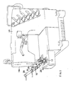
- Fig. 1 shows a flat sewing machine with a needle home position stopping device, in which a curved cover thread laying finger 12 reciprocating laterally before the needle captures and pulls the cover thread in the going stroke, and releases the cover thread in the returning stroke after reaching the left dead center, and a cover thread cutter 16 is installed at the lower left side of the head 14a of the sewing machine 14.
- the cover thread cutter 16 comprises a bracket 20 mounted on a support shaft 18 projecting sideways from the head 14a, a cutter support frame 24 attached with screws 22 to the bracket 20 so as to be directed to a left needle N1 obliquely nose-diving from the left side of the left needle N1, a fixed cutter 28 fixed with screw 26 to the front end of the cutter support frame 24, with the blade tip adjusted vertically by an adjusting screw 27, as shown in Fig.
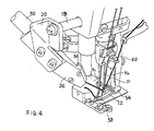
- a hook for thread cutter 32 which is supported by an air cylinder 30 mounted on the cutter support frame 24 and moves back and forth as sliding on the fixed cutter 28 obliquely nose-diving from behind the left side of the left needle N1 to before the needles N1, N2 by the operation of the air cylinder 30, a holder 36 for pinching the hook for thread cutter 32 together with the frame 24, being attached to the cutter support frame 24 with setscrews 34, a first spring device 38 mounted on the holder 36 for tightly pressing the hook for thread cutter 32 to the fixed cutter 28, and a second spring device 40 mounted on the holder 36 for lightly and elastically contact with the hook 32 so as to lightly hold the cut end of the cover thread with a minimum required pressing pressure the second spring device being positioned at the front end side of the hook for thread cutter 32 than the first spring device 38, wherein the first and second spring devices 38 and 40 are composed of spring retainers 46 and 48 of which sections to be engaged with recesses 42 and 44 arranged in the holder 36 are in circular or square cap form and surface contacting with the
- the coil spring 50 of the first spring device 38 has a strong spring force, while the coil spring 52 of the second spring device 40 is designed to have a weak spring force.
- the first spring device 38 is larger in size than the second spring device 40 so as to be apparently distinguished from the second spring device 40 when assembling. For easier distinguishing, different colors, numbers or codes may be used.
- the hook for thread cutter 32 which is drawn back by the operation of the air cylinder 30 reaches above the curved cover thread laying finger 12 when moved forward, and when the hook retreats, the hook for thread cutter 32 is designed to capture the cover thread 56 extending from the hook 13 of the curved cover thread laying finger 12 to the cover thread guide 54, at the left side of the left needle N1 near the hook 13.
- a notch hole 58 is formed in the finger 12 so as to prevent collision with the hook for thread cutter 32 against the finger 12 when the hook for thread cutter 32 moved forward.
- numeral 60 is a cover thread movable guide attached to a needle holder 62.
- Numeral 64 is a needle thread, and 66 is a presser foot.
- cutting of the cover thread and holding of the thread end are operated as follows.
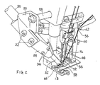
- the needles N1, N2 are stopped at the top dead center, and the curved cover thread laying finger 12 captures and pulls the cover thread 56 and reaches near the left dead center and stops.
- the hook for thread cutter 32 is projected forward head down obliquely from behind the left side of the left needle N1.
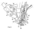
- the hook for thread cutter 32 captures the cover thread 56 between the hook 13 and the cover thread guide 54 (Fig. 2), and pulls back obliquely to the left side (Fig. 3).
- the cover thread 56 is placed between the left needle N1 and the right needle N2, and is caught in the left needle N1 and is bent backward obliquely to the left.
- the hook for thread cutter 32 pulls the cover thread 56 and retracts from the fixed cutter 28, the thread 56 is cut off, and the cut thread end of the thread supply source is pinched between the second spring device 40 and the hook for thread cutter 32.
- the cover thread 56 is pulled out of the cover thread guide 54, and is hooked on the right needle N2 from the rear side and is hooked on the left needle N1 from the front side to be held, so that the cover thread is sewn into the first needle thread seam when starting the next sewing work.
Landscapes
- Engineering & Computer Science (AREA)
- Textile Engineering (AREA)
- Sewing Machines And Sewing (AREA)
Applications Claiming Priority (4)
| Application Number | Priority Date | Filing Date | Title |
|---|---|---|---|
| JP1166013A JPH0738914B2 (ja) | 1989-06-27 | 1989-06-27 | 多本針ミシンの上飾り糸切断方法及びその装置 |
| JP166013/89 | 1989-06-27 | ||
| JP5956/90 | 1990-01-24 | ||
| JP595690U JPH0538716Y2 (de) | 1990-01-24 | 1990-01-24 |
Publications (3)
| Publication Number | Publication Date |
|---|---|
| EP0405903A2 true EP0405903A2 (de) | 1991-01-02 |
| EP0405903A3 EP0405903A3 (en) | 1991-07-10 |
| EP0405903B1 EP0405903B1 (de) | 1996-08-14 |
Family
ID=26339995
Family Applications (1)
| Application Number | Title | Priority Date | Filing Date |
|---|---|---|---|
| EP90306954A Expired - Lifetime EP0405903B1 (de) | 1989-06-27 | 1990-06-26 | Verfahren und Vorrichtung zum Abschneiden des Deckfadens einer Mehrnadelnähmaschine |
Country Status (3)
| Country | Link |
|---|---|
| US (1) | US5127350A (de) |
| EP (1) | EP0405903B1 (de) |
| DE (1) | DE69028050T2 (de) |
Cited By (1)
| Publication number | Priority date | Publication date | Assignee | Title |
|---|---|---|---|---|
| FR2666596A1 (fr) * | 1990-09-06 | 1992-03-13 | Union Special Gmbh | Dispositif coupeur pour separer un fil de fond de dessus d'une machine a coudre a point de chaine et a plusieurs aiguilles. |
Families Citing this family (6)
| Publication number | Priority date | Publication date | Assignee | Title |
|---|---|---|---|---|
| JPH04348795A (ja) * | 1991-05-27 | 1992-12-03 | Aisin Seiki Co Ltd | ミシンの上糸保持装置 |
| USD407774S (en) | 1998-06-13 | 1999-04-06 | Weiss Eric R | Golf club holder |
| US6286445B1 (en) * | 1999-09-24 | 2001-09-11 | Clinton Industries, Inc. | Unitary double-acting piston thread cutter assembly |
| TW451958U (en) * | 2000-07-12 | 2001-08-21 | Kaulin Mfg Co Ltd | Upper fork weft cutter for sewing machine |
| US6332419B1 (en) * | 2001-03-20 | 2001-12-25 | Fei-Lung Ku | Auxillary device of a sewing machine |
| US20100080653A1 (en) * | 2008-09-26 | 2010-04-01 | Lewis Thomas H | Pavement Seal, Installation Machine And Method Of Installation |
Family Cites Families (10)
| Publication number | Priority date | Publication date | Assignee | Title |
|---|---|---|---|---|
| DE1485429C3 (de) * | 1965-05-08 | 1973-09-20 | Union Special Maschinenfabrik Gmbh, 7000 Stuttgart | Abschneidemnchtung fur Doppel kettenstich Nahmaschinen |
| US3584589A (en) * | 1970-01-27 | 1971-06-15 | Clinton Ind | Thread trimmer |
| US3848555A (en) * | 1973-12-10 | 1974-11-19 | R Boser | Sewing machine cutting device |
| IT1017974B (it) * | 1974-08-07 | 1977-08-10 | Rockwell Rimoldi Spa | Dispositivo tagliafilo per filo di copertura di una macchina per cucire |
| US4450781A (en) * | 1982-04-01 | 1984-05-29 | Usm Corporation | Thread wiping mechanism |
| JPS5955286A (ja) * | 1982-09-22 | 1984-03-30 | ヤマトミシン製造株式会社 | 平複数針ミシンの飾糸自動切断装置 |
| DE3333310C2 (de) * | 1983-09-15 | 1985-08-29 | Union Special Gmbh, 7000 Stuttgart | Nähmaschine mit mindestens einer oszillierenden Nadel |
| US4683828A (en) * | 1985-09-04 | 1987-08-04 | Yamato Mishin Seizo Kabushiki Kaisha | Ornamental thread automatic cutting device of flat plural-needles sewing machine |
| JPS6445796A (en) * | 1987-08-13 | 1989-02-20 | Toshiba Corp | Apparatus for pulling up si single crystal and method therefor |
| DE3729581A1 (de) * | 1987-09-04 | 1989-03-23 | Union Special Gmbh | Abschneidvorrichtung zum trennen des legfadens bei einer mehrnadelnaehmaschine |
-
1990
- 1990-06-25 US US07/543,165 patent/US5127350A/en not_active Expired - Lifetime
- 1990-06-26 EP EP90306954A patent/EP0405903B1/de not_active Expired - Lifetime
- 1990-06-26 DE DE69028050T patent/DE69028050T2/de not_active Expired - Fee Related
Cited By (4)
| Publication number | Priority date | Publication date | Assignee | Title |
|---|---|---|---|---|
| FR2666596A1 (fr) * | 1990-09-06 | 1992-03-13 | Union Special Gmbh | Dispositif coupeur pour separer un fil de fond de dessus d'une machine a coudre a point de chaine et a plusieurs aiguilles. |
| GB2248074A (en) * | 1990-09-06 | 1992-03-25 | Union Special Gmbh | Thread cutting in multiple needle chainstitch sewing machine |
| US5178084A (en) * | 1990-09-06 | 1993-01-12 | Union Special Gmbh | Multiple needle chainstitch sewing machine |
| GB2248074B (en) * | 1990-09-06 | 1994-05-18 | Union Special Gmbh | Multiple needle chainstitch sewing machine |
Also Published As
| Publication number | Publication date |
|---|---|
| EP0405903B1 (de) | 1996-08-14 |
| DE69028050D1 (de) | 1996-09-19 |
| EP0405903A3 (en) | 1991-07-10 |
| US5127350A (en) | 1992-07-07 |
| DE69028050T2 (de) | 1997-01-23 |
Similar Documents
| Publication | Publication Date | Title |
|---|---|---|
| US4635575A (en) | Sewing machine for sewing a rubber strip to a textile fabric | |
| US3532065A (en) | Thread cutting device for sewing machines | |
| EP0405903A2 (de) | Verfahren und Vorrichtung zum Abschneiden des Deckfadens einer Mehrnadelnähmaschine | |
| US5025739A (en) | Needle thread wiper of sewing machine | |
| US2318200A (en) | Automatic cutoff for sewing machines | |
| JPH04288193A (ja) | 多針−環縫ミシンにおけるルーパ糸を切断するための切断装置 | |
| US5431119A (en) | Thread end holding device for a sewing machine | |
| US4886005A (en) | Thread undercut attachment for a multi-needle sewing machine | |
| JPS5955286A (ja) | 平複数針ミシンの飾糸自動切断装置 | |
| JP5057303B2 (ja) | 上飾り機構付きミシン | |
| JPS6029183A (ja) | 縁かがり縫いミシンに用いる空環縫い込み装置 | |
| JPH0515916Y2 (de) | ||
| JPH0738914B2 (ja) | 多本針ミシンの上飾り糸切断方法及びその装置 | |
| JPH0871283A (ja) | 工業用ミシンの糸切断装置 | |
| JP2584981Y2 (ja) | ミシンの糸切り装置 | |
| JPH0674Y2 (ja) | ミシンの下糸クランプ装置 | |
| JPH0752700Y2 (ja) | ミシンの下糸切り装置 | |
| JPH10118377A (ja) | オーバーロックミシンにおける空環縫込み装置 | |
| CN219430281U (zh) | 一种缝纫机的防鸟巢装置 | |
| JPH0642629Y2 (ja) | 単環縫いミシンの糸切り装置 | |
| CN219408609U (zh) | 一种利用手爪上料的对折装置及鞋带袢加工设备 | |
| JPH0794253B2 (ja) | 環糸形成機構における糸捕捉成否判別装置 | |
| JPH0636586U (ja) | ミシンの糸払い装置 | |
| JPH0736636Y2 (ja) | 多列二重環縫いミシンの糸切り装置 | |
| JPS6145796A (ja) | 多本針ミシンの糸切断方法及び装置 |
Legal Events
| Date | Code | Title | Description |
|---|---|---|---|
| PUAI | Public reference made under article 153(3) epc to a published international application that has entered the european phase |
Free format text: ORIGINAL CODE: 0009012 |
|
| AK | Designated contracting states |
Kind code of ref document: A2 Designated state(s): DE FR GB IT |
|
| PUAL | Search report despatched |
Free format text: ORIGINAL CODE: 0009013 |
|
| AK | Designated contracting states |
Kind code of ref document: A3 Designated state(s): DE FR GB IT |
|
| 17P | Request for examination filed |
Effective date: 19911213 |
|
| 17Q | First examination report despatched |
Effective date: 19930726 |
|
| GRAH | Despatch of communication of intention to grant a patent |
Free format text: ORIGINAL CODE: EPIDOS IGRA |
|
| GRAH | Despatch of communication of intention to grant a patent |
Free format text: ORIGINAL CODE: EPIDOS IGRA |
|
| GRAA | (expected) grant |
Free format text: ORIGINAL CODE: 0009210 |
|
| AK | Designated contracting states |
Kind code of ref document: B1 Designated state(s): DE FR GB IT |
|
| ITF | It: translation for a ep patent filed | ||
| REF | Corresponds to: |
Ref document number: 69028050 Country of ref document: DE Date of ref document: 19960919 |
|
| ET | Fr: translation filed | ||
| PLBE | No opposition filed within time limit |
Free format text: ORIGINAL CODE: 0009261 |
|
| STAA | Information on the status of an ep patent application or granted ep patent |
Free format text: STATUS: NO OPPOSITION FILED WITHIN TIME LIMIT |
|
| 26N | No opposition filed | ||
| REG | Reference to a national code |
Ref country code: GB Ref legal event code: IF02 |
|
| PGFP | Annual fee paid to national office [announced via postgrant information from national office to epo] |
Ref country code: DE Payment date: 20080731 Year of fee payment: 19 |
|
| PGFP | Annual fee paid to national office [announced via postgrant information from national office to epo] |
Ref country code: FR Payment date: 20080617 Year of fee payment: 19 Ref country code: IT Payment date: 20080628 Year of fee payment: 19 |
|
| PGFP | Annual fee paid to national office [announced via postgrant information from national office to epo] |
Ref country code: GB Payment date: 20080630 Year of fee payment: 19 |
|
| GBPC | Gb: european patent ceased through non-payment of renewal fee |
Effective date: 20090626 |
|
| REG | Reference to a national code |
Ref country code: FR Ref legal event code: ST Effective date: 20100226 |
|
| PG25 | Lapsed in a contracting state [announced via postgrant information from national office to epo] |
Ref country code: FR Free format text: LAPSE BECAUSE OF NON-PAYMENT OF DUE FEES Effective date: 20090630 |
|
| PG25 | Lapsed in a contracting state [announced via postgrant information from national office to epo] |
Ref country code: GB Free format text: LAPSE BECAUSE OF NON-PAYMENT OF DUE FEES Effective date: 20090626 |
|
| PG25 | Lapsed in a contracting state [announced via postgrant information from national office to epo] |
Ref country code: DE Free format text: LAPSE BECAUSE OF NON-PAYMENT OF DUE FEES Effective date: 20100101 |
|
| PG25 | Lapsed in a contracting state [announced via postgrant information from national office to epo] |
Ref country code: IT Free format text: LAPSE BECAUSE OF NON-PAYMENT OF DUE FEES Effective date: 20090626 |