EP0405903A2 - Method and apparatus for cutting cover thread of multi-needle sewing machine - Google Patents
Method and apparatus for cutting cover thread of multi-needle sewing machine Download PDFInfo
- Publication number
- EP0405903A2 EP0405903A2 EP90306954A EP90306954A EP0405903A2 EP 0405903 A2 EP0405903 A2 EP 0405903A2 EP 90306954 A EP90306954 A EP 90306954A EP 90306954 A EP90306954 A EP 90306954A EP 0405903 A2 EP0405903 A2 EP 0405903A2
- Authority
- EP
- European Patent Office
- Prior art keywords
- thread
- cutter
- hook
- cover thread
- cover
- Prior art date
- Legal status (The legal status is an assumption and is not a legal conclusion. Google has not performed a legal analysis and makes no representation as to the accuracy of the status listed.)
- Granted
Links
Images

Classifications
-
- D—TEXTILES; PAPER
- D05—SEWING; EMBROIDERING; TUFTING
- D05B—SEWING
- D05B65/00—Devices for severing the needle or lower thread
-
- D—TEXTILES; PAPER
- D05—SEWING; EMBROIDERING; TUFTING
- D05B—SEWING
- D05B65/00—Devices for severing the needle or lower thread
- D05B65/06—Devices for severing the needle or lower thread and for disposing of the severed thread end ; Catching or wiping devices for the severed thread
-
- D—TEXTILES; PAPER
- D05—SEWING; EMBROIDERING; TUFTING
- D05B—SEWING
- D05B57/00—Loop takers, e.g. loopers
- D05B57/02—Loop takers, e.g. loopers for chain-stitch sewing machines, e.g. oscillating
-
- D—TEXTILES; PAPER
- D05—SEWING; EMBROIDERING; TUFTING
- D05D—INDEXING SCHEME ASSOCIATED WITH SUBCLASSES D05B AND D05C, RELATING TO SEWING, EMBROIDERING AND TUFTING
- D05D2303/00—Applied objects or articles
- D05D2303/08—Cordage
Definitions
- the present invention relates to a method and its apparatus for cutting a cover thread of a multi-needle sewing machine using cover thread.
- a device for automatically cutting the cover thread consecutive to the needle thread seam at the end of sewing after the sewing work is known.
- the cut end of the cover thread at the cut-off thread supply source side is directly clamped in the thread cutter, and is caught by a specified needle or captured by the curved cover thread laying finger when starting next sewing work, so as to be securely sewn into the first needle thread seam.
- the cover thread extending from the right needle thread seam at the end of sewing into the cover thread guide above the finger is captured and cut by the hook for thread cutter which reciprocates from the right oblique rear side of the right needle.
- the cut end of the cover thread is directly clamped in the thread cutter, so as to be captured by the finger when starting next sewing work.
- These conventional thread cutters are composed of a fixed cutter, a hook for thread cutter which moves in and out as sliding on the fixed cutter, and a leaf spring for pressing the hook to the fixed cutter, in which the cover thread captured by the hook is pulled to the fixed cutter and is cut off by the cutter, and the cut end of the cover thread at the cut-off thread supply source side is pinched and held by and between the hook and the leaf spring.
- the hook is tightly pressed to the fixed cutter by intensifying the spring pressure of the leaf spring to cut the thread securely, the holding force to the cut thread end increases, and the thread end may not easily slip off from the hook and leaf spring when starting next sewing, which may lead to uneven pulling of the cloth or breakage of the needle.
- the invention is hence intended to capture the cover thread above the curved cover thread laying finger so that the cover thread may be easily and securely captured even in the case of a thick fabric. In this case, when starting next sewing work, it must be arranged to hold the thread end so that the curved cover thread laying finger may securely capture the cover thread.
- the hook for thread cutter is designed to retreat from the cutting position obliquely behind the left side of the left needle to capture the cover thread above the curved cover thread laying finger to pull up to the cutting position, so as to cut off and hold the thread end.
- the hook for thread cutter draws back toward above the curved cover thread laying finger, the cover thread can be captured, regardless of the thickness of the fabric.
- the captured cover thread passes through between specified needles, when the hook for thread cutter retreats behind obliquely to the left side, and is applied on the left side needle necessary for forming the next first seam and is held in this state even after being cut off. Therefore when starting next sewing work, same as at the time of usual seam forming, the cover thread is captured by the curved cover thread laying finger and is sewn into the first needle thread seam, so that skip stitch does not occur.
- the cover thread is maintained in a state of extending from the left side of the right side needle up to the cover thread guide through the rear side of right side needle. Therefore when starting next sewing work, it is securely sewn into the first needle thread seam.
- the invention presents a thread cutter having a spring device comprising a coil spring and a spring retainer, wherein the cut end of the cover thread is held by the spring device with a weaker spring force than the spring for pressing the hook for thread cutter to the fixed cutter.
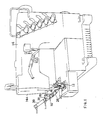
- Fig. 1 shows a flat sewing machine with a needle home position stopping device, in which a curved cover thread laying finger 12 reciprocating laterally before the needle captures and pulls the cover thread in the going stroke, and releases the cover thread in the returning stroke after reaching the left dead center, and a cover thread cutter 16 is installed at the lower left side of the head 14a of the sewing machine 14.
- the cover thread cutter 16 comprises a bracket 20 mounted on a support shaft 18 projecting sideways from the head 14a, a cutter support frame 24 attached with screws 22 to the bracket 20 so as to be directed to a left needle N1 obliquely nose-diving from the left side of the left needle N1, a fixed cutter 28 fixed with screw 26 to the front end of the cutter support frame 24, with the blade tip adjusted vertically by an adjusting screw 27, as shown in Fig.
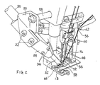
- a hook for thread cutter 32 which is supported by an air cylinder 30 mounted on the cutter support frame 24 and moves back and forth as sliding on the fixed cutter 28 obliquely nose-diving from behind the left side of the left needle N1 to before the needles N1, N2 by the operation of the air cylinder 30, a holder 36 for pinching the hook for thread cutter 32 together with the frame 24, being attached to the cutter support frame 24 with setscrews 34, a first spring device 38 mounted on the holder 36 for tightly pressing the hook for thread cutter 32 to the fixed cutter 28, and a second spring device 40 mounted on the holder 36 for lightly and elastically contact with the hook 32 so as to lightly hold the cut end of the cover thread with a minimum required pressing pressure the second spring device being positioned at the front end side of the hook for thread cutter 32 than the first spring device 38, wherein the first and second spring devices 38 and 40 are composed of spring retainers 46 and 48 of which sections to be engaged with recesses 42 and 44 arranged in the holder 36 are in circular or square cap form and surface contacting with the
- the coil spring 50 of the first spring device 38 has a strong spring force, while the coil spring 52 of the second spring device 40 is designed to have a weak spring force.
- the first spring device 38 is larger in size than the second spring device 40 so as to be apparently distinguished from the second spring device 40 when assembling. For easier distinguishing, different colors, numbers or codes may be used.
- the hook for thread cutter 32 which is drawn back by the operation of the air cylinder 30 reaches above the curved cover thread laying finger 12 when moved forward, and when the hook retreats, the hook for thread cutter 32 is designed to capture the cover thread 56 extending from the hook 13 of the curved cover thread laying finger 12 to the cover thread guide 54, at the left side of the left needle N1 near the hook 13.
- a notch hole 58 is formed in the finger 12 so as to prevent collision with the hook for thread cutter 32 against the finger 12 when the hook for thread cutter 32 moved forward.
- numeral 60 is a cover thread movable guide attached to a needle holder 62.
- Numeral 64 is a needle thread, and 66 is a presser foot.
- cutting of the cover thread and holding of the thread end are operated as follows.
- the needles N1, N2 are stopped at the top dead center, and the curved cover thread laying finger 12 captures and pulls the cover thread 56 and reaches near the left dead center and stops.
- the hook for thread cutter 32 is projected forward head down obliquely from behind the left side of the left needle N1.
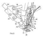
- the hook for thread cutter 32 captures the cover thread 56 between the hook 13 and the cover thread guide 54 (Fig. 2), and pulls back obliquely to the left side (Fig. 3).
- the cover thread 56 is placed between the left needle N1 and the right needle N2, and is caught in the left needle N1 and is bent backward obliquely to the left.
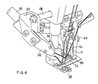
- the hook for thread cutter 32 pulls the cover thread 56 and retracts from the fixed cutter 28, the thread 56 is cut off, and the cut thread end of the thread supply source is pinched between the second spring device 40 and the hook for thread cutter 32.
- the cover thread 56 is pulled out of the cover thread guide 54, and is hooked on the right needle N2 from the rear side and is hooked on the left needle N1 from the front side to be held, so that the cover thread is sewn into the first needle thread seam when starting the next sewing work.
Abstract
Description
- The present invention relates to a method and its apparatus for cutting a cover thread of a multi-needle sewing machine using cover thread.
- A device for automatically cutting the cover thread consecutive to the needle thread seam at the end of sewing after the sewing work, is known.
- Among the known devices, as disclosed in the Japanese Laid-open Patent Sho. 57-128195, Utility Model Sho. 58-177086, Patent Sho. 59-55286, and Utility Model Sho. 60-179282, at the end of sewing when the needle and feed dog reach the top dead center and the curved cover thread layer finger reaches the left dead center to stop, the cover thread from the right needle thread seam at the end of sewing to the hook of the curved cover thread laying finger is captured and cut by the hook for thread cutter which reciprocates to start from the left oblique rear side of the left needle or the right oblique operator side of the left needle. The cut end of the cover thread at the cut-off thread supply source side is directly clamped in the thread cutter, and is caught by a specified needle or captured by the curved cover thread laying finger when starting next sewing work, so as to be securely sewn into the first needle thread seam. As disclosed in the Japanese Laid-open Patent Sho. 61-45796, at the end of sewing when the needle and feed dog are stopped at the bottom dead center and the finger at the right dead center, the cover thread extending from the right needle thread seam at the end of sewing into the cover thread guide above the finger is captured and cut by the hook for thread cutter which reciprocates from the right oblique rear side of the right needle. The cut end of the cover thread is directly clamped in the thread cutter, so as to be captured by the finger when starting next sewing work.
- In all these conventional machines, however, since the cover thread is designed to be captured as the hook for thread cutter advances into the space between the top surface of the presser foot and the curved cover thread laying finger, the spacing between the top surface of the presser foot and the curved cover thread laying finger becomes narrow in the case of a thick fabric, so that the hook for thread cutter may not get in easily.
- These conventional thread cutters are composed of a fixed cutter, a hook for thread cutter which moves in and out as sliding on the fixed cutter, and a leaf spring for pressing the hook to the fixed cutter, in which the cover thread captured by the hook is pulled to the fixed cutter and is cut off by the cutter, and the cut end of the cover thread at the cut-off thread supply source side is pinched and held by and between the hook and the leaf spring. In such devices, however, although it is advantageous that the hook is tightly pressed to the fixed cutter by intensifying the spring pressure of the leaf spring to cut the thread securely, the holding force to the cut thread end increases, and the thread end may not easily slip off from the hook and leaf spring when starting next sewing, which may lead to uneven pulling of the cloth or breakage of the needle.
- Though it is not a thread cutter for cover thread, a device having a leaf spring for holding the thread end by lightly and elastically contacting with the hook for thread cutter, and a leaf spring for pressing the hook to the fixed cutter, is known. An example of this type is shown in the Japanese Utility Model Publication Sho. 63-10149. According to this device, the thread may be cut off securely by properly adjusting the spring pressures of individual springs, and the cut thread end may be lightly held with a minimum required pressing pressure. However, since the leaf spring is of cantilever type and its free end is pressed to the hook for thread cutter, the leaf spring must be long enough for lightly and elastically contacting with the hook for thread cutter in the case of leaf spring for holding the thread end, and the design is not compact. In this type, the contact area with the hook is small and the holding force is lowered, so that the thread end holding is unstable, and it is always needed to adjust the spring force.
- The invention is hence intended to capture the cover thread above the curved cover thread laying finger so that the cover thread may be easily and securely captured even in the case of a thick fabric. In this case, when starting next sewing work, it must be arranged to hold the thread end so that the curved cover thread laying finger may securely capture the cover thread.
- It is therefore a primary object of the invention to present a method of capturing the cover thread above the curved cover thread laying finger by the hook for thread cutter, and capturing the cover thread securely by the curved cover thread laying finger when starting next sewing work to cause the cover thread to be sewn into the first seam, thereby preventing skipping of the seam.
- To achieve the above object, at the end of sewing, the hook for thread cutter is designed to retreat from the cutting position obliquely behind the left side of the left needle to capture the cover thread above the curved cover thread laying finger to pull up to the cutting position, so as to cut off and hold the thread end. According to the invention, since the hook for thread cutter draws back toward above the curved cover thread laying finger, the cover thread can be captured, regardless of the thickness of the fabric. The captured cover thread passes through between specified needles, when the hook for thread cutter retreats behind obliquely to the left side, and is applied on the left side needle necessary for forming the next first seam and is held in this state even after being cut off. Therefore when starting next sewing work, same as at the time of usual seam forming, the cover thread is captured by the curved cover thread laying finger and is sewn into the first needle thread seam, so that skip stitch does not occur.
- In this method, same as in ordinary seam forming, the cover thread is maintained in a state of extending from the left side of the right side needle up to the cover thread guide through the rear side of right side needle. Therefore when starting next sewing work, it is securely sewn into the first needle thread seam.
- It is another object of the invention to present a thread cutter in a compact design, by disposing a spring for holding the thread, instead of the leaf spring, in addition to the spring for pressing the hook for thread cutter to the fixed cutter, so that the cut thread end may be securely held with a proper pressing pressure and that the thread may slip off easily when starting next sewing work.
- To achieve the above object, the invention presents a thread cutter having a spring device comprising a coil spring and a spring retainer, wherein the cut end of the cover thread is held by the spring device with a weaker spring force than the spring for pressing the hook for thread cutter to the fixed cutter.
- Other objects and features of the invention will be better understood and appreciated from the following detailed description taken in conjunction with the accompanying drawings.
-
- Fig. 1 is a prespective view of a flat sewing machine with a cover thread cutter,
- Fig. 2 is a perspective view when the hook for thread cutter is advanced above the curved cover thread laying finger at the time of cutting the cover thread,
- Fig. 3 is a perspective view showing the state of capturing of the cover thread by the hook for thread cutter,
- Fig. 4 is a perspective view showing the cut-off state of the cover thread, and
- Fig. 5 is a partial sectional side view of essential parts of the thread cutter.
- Fig. 1 shows a flat sewing machine with a needle home position stopping device, in which a curved cover
thread laying finger 12 reciprocating laterally before the needle captures and pulls the cover thread in the going stroke, and releases the cover thread in the returning stroke after reaching the left dead center, and acover thread cutter 16 is installed at the lower left side of the head 14a of thesewing machine 14. - The
cover thread cutter 16 comprises abracket 20 mounted on asupport shaft 18 projecting sideways from the head 14a, acutter support frame 24 attached withscrews 22 to thebracket 20 so as to be directed to a left needle N1 obliquely nose-diving from the left side of the left needle N1, a fixedcutter 28 fixed withscrew 26 to the front end of thecutter support frame 24, with the blade tip adjusted vertically by an adjustingscrew 27, as shown in Fig. 5, a hook forthread cutter 32 which is supported by anair cylinder 30 mounted on thecutter support frame 24 and moves back and forth as sliding on the fixedcutter 28 obliquely nose-diving from behind the left side of the left needle N1 to before the needles N1, N2 by the operation of theair cylinder 30, aholder 36 for pinching the hook forthread cutter 32 together with theframe 24, being attached to thecutter support frame 24 withsetscrews 34, afirst spring device 38 mounted on theholder 36 for tightly pressing the hook forthread cutter 32 to the fixedcutter 28, and asecond spring device 40 mounted on theholder 36 for lightly and elastically contact with thehook 32 so as to lightly hold the cut end of the cover thread with a minimum required pressing pressure the second spring device being positioned at the front end side of the hook forthread cutter 32 than thefirst spring device 38, wherein the first andsecond spring devices spring retainers recesses holder 36 are in circular or square cap form and surface contacting with the hook forthread cutter 32 is a flat plane so as to enhance the holding force, andcoil springs recesses spring retainers coil spring 50 of thefirst spring device 38 has a strong spring force, while thecoil spring 52 of thesecond spring device 40 is designed to have a weak spring force. Thefirst spring device 38 is larger in size than thesecond spring device 40 so as to be apparently distinguished from thesecond spring device 40 when assembling. For easier distinguishing, different colors, numbers or codes may be used. - The hook for
thread cutter 32 which is drawn back by the operation of theair cylinder 30 reaches above the curved coverthread laying finger 12 when moved forward, and when the hook retreats, the hook forthread cutter 32 is designed to capture thecover thread 56 extending from thehook 13 of the curved coverthread laying finger 12 to thecover thread guide 54, at the left side of the left needle N1 near thehook 13. Anotch hole 58 is formed in thefinger 12 so as to prevent collision with the hook forthread cutter 32 against thefinger 12 when the hook forthread cutter 32 moved forward. - In the drawing,
numeral 60 is a cover thread movable guide attached to aneedle holder 62. Numeral 64 is a needle thread, and 66 is a presser foot. - In this device composed as described herein, cutting of the cover thread and holding of the thread end are operated as follows.
- When sewing is over and the pedal (not shown) is released by the operator, the needles N1, N2 are stopped at the top dead center, and the curved cover
thread laying finger 12 captures and pulls thecover thread 56 and reaches near the left dead center and stops. In sequence, by the operation of the air cylinder, the hook forthread cutter 32 is projected forward head down obliquely from behind the left side of the left needle N1. When the front end of hook forthread cutter 32 reaches above the curved cover thread laying finger and then draws back rearward, the hook forthread cutter 32 captures thecover thread 56 between thehook 13 and the cover thread guide 54 (Fig. 2), and pulls back obliquely to the left side (Fig. 3). At this time, thecover thread 56 is placed between the left needle N1 and the right needle N2, and is caught in the left needle N1 and is bent backward obliquely to the left. When the hook forthread cutter 32 pulls thecover thread 56 and retracts from thefixed cutter 28, thethread 56 is cut off, and the cut thread end of the thread supply source is pinched between thesecond spring device 40 and the hook forthread cutter 32. In this state, thecover thread 56 is pulled out of thecover thread guide 54, and is hooked on the right needle N2 from the rear side and is hooked on the left needle N1 from the front side to be held, so that the cover thread is sewn into the first needle thread seam when starting the next sewing work.
Claims (7)
Applications Claiming Priority (4)
| Application Number | Priority Date | Filing Date | Title |
|---|---|---|---|
| JP1166013A JPH0738914B2 (en) | 1989-06-27 | 1989-06-27 | Method and apparatus for cutting decorative thread of multi-needle sewing machine |
| JP166013/89 | 1989-06-27 | ||
| JP595690U JPH0538716Y2 (en) | 1990-01-24 | 1990-01-24 | |
| JP5956/90 | 1990-01-24 |
Publications (3)
| Publication Number | Publication Date |
|---|---|
| EP0405903A2 true EP0405903A2 (en) | 1991-01-02 |
| EP0405903A3 EP0405903A3 (en) | 1991-07-10 |
| EP0405903B1 EP0405903B1 (en) | 1996-08-14 |
Family
ID=26339995
Family Applications (1)
| Application Number | Title | Priority Date | Filing Date |
|---|---|---|---|
| EP90306954A Expired - Lifetime EP0405903B1 (en) | 1989-06-27 | 1990-06-26 | Method and apparatus for cutting cover thread of multi-needle sewing machine |
Country Status (3)
| Country | Link |
|---|---|
| US (1) | US5127350A (en) |
| EP (1) | EP0405903B1 (en) |
| DE (1) | DE69028050T2 (en) |
Cited By (1)
| Publication number | Priority date | Publication date | Assignee | Title |
|---|---|---|---|---|
| FR2666596A1 (en) * | 1990-09-06 | 1992-03-13 | Union Special Gmbh | CUTTING DEVICE FOR SEPARATING A BACKGROUND THREAD FROM A CHAIN STITCHING MACHINE WITH MULTIPLE NEEDLES. |
Families Citing this family (5)
| Publication number | Priority date | Publication date | Assignee | Title |
|---|---|---|---|---|
| JPH04348795A (en) * | 1991-05-27 | 1992-12-03 | Aisin Seiki Co Ltd | Needle thread holder for sewing machine |
| US6286445B1 (en) * | 1999-09-24 | 2001-09-11 | Clinton Industries, Inc. | Unitary double-acting piston thread cutter assembly |
| TW451958U (en) * | 2000-07-12 | 2001-08-21 | Kaulin Mfg Co Ltd | Upper fork weft cutter for sewing machine |
| US6332419B1 (en) * | 2001-03-20 | 2001-12-25 | Fei-Lung Ku | Auxillary device of a sewing machine |
| US20100080653A1 (en) * | 2008-09-26 | 2010-04-01 | Lewis Thomas H | Pavement Seal, Installation Machine And Method Of Installation |
Citations (4)
| Publication number | Priority date | Publication date | Assignee | Title |
|---|---|---|---|---|
| US3848555A (en) * | 1973-12-10 | 1974-11-19 | R Boser | Sewing machine cutting device |
| DE2337568A1 (en) * | 1973-07-24 | 1975-02-06 | Ullrich Walter | Sewing machine thread cutting system - has a hook to catch the thread and draw it against a cutting edge |
| DE3531595A1 (en) * | 1985-09-04 | 1987-03-05 | Yamato Sewing Machine Mfg | METHOD AND DEVICE FOR THE AUTOMATIC CUTTING OF THE DECORATIVE THREAD IN ONE AND FOR A MULTI-NEEDLE FLAT SEWING MACHINE |
| FR2620140A1 (en) * | 1987-09-04 | 1989-03-10 | Union Special Gmbh | CUTTING DEVICE FOR SEPARATING THE COVERING THREAD IN A SEWING MACHINE WITH MULTIPLE NEEDLES |
Family Cites Families (7)
| Publication number | Priority date | Publication date | Assignee | Title |
|---|---|---|---|---|
| DE1485429C3 (en) * | 1965-05-08 | 1973-09-20 | Union Special Maschinenfabrik Gmbh, 7000 Stuttgart | Cutting device for double chainstitch sewing machines |
| US3584589A (en) * | 1970-01-27 | 1971-06-15 | Clinton Ind | Thread trimmer |
| IT1017974B (en) * | 1974-08-07 | 1977-08-10 | Rockwell Rimoldi Spa | THREAD CUTTER DEVICE FOR COVERING THREAD OF A SEWING MACHINE |
| US4450781A (en) * | 1982-04-01 | 1984-05-29 | Usm Corporation | Thread wiping mechanism |
| JPS5955286A (en) * | 1982-09-22 | 1984-03-30 | ヤマトミシン製造株式会社 | Method and apparatus for automatically cutting decorative yarn of flat multi-needle sewing machine |
| DE3333310C2 (en) * | 1983-09-15 | 1985-08-29 | Union Special Gmbh, 7000 Stuttgart | Sewing machine with at least one oscillating needle |
| JPS6445796A (en) * | 1987-08-13 | 1989-02-20 | Toshiba Corp | Apparatus for pulling up si single crystal and method therefor |
-
1990
- 1990-06-25 US US07/543,165 patent/US5127350A/en not_active Expired - Lifetime
- 1990-06-26 DE DE69028050T patent/DE69028050T2/en not_active Expired - Fee Related
- 1990-06-26 EP EP90306954A patent/EP0405903B1/en not_active Expired - Lifetime
Patent Citations (4)
| Publication number | Priority date | Publication date | Assignee | Title |
|---|---|---|---|---|
| DE2337568A1 (en) * | 1973-07-24 | 1975-02-06 | Ullrich Walter | Sewing machine thread cutting system - has a hook to catch the thread and draw it against a cutting edge |
| US3848555A (en) * | 1973-12-10 | 1974-11-19 | R Boser | Sewing machine cutting device |
| DE3531595A1 (en) * | 1985-09-04 | 1987-03-05 | Yamato Sewing Machine Mfg | METHOD AND DEVICE FOR THE AUTOMATIC CUTTING OF THE DECORATIVE THREAD IN ONE AND FOR A MULTI-NEEDLE FLAT SEWING MACHINE |
| FR2620140A1 (en) * | 1987-09-04 | 1989-03-10 | Union Special Gmbh | CUTTING DEVICE FOR SEPARATING THE COVERING THREAD IN A SEWING MACHINE WITH MULTIPLE NEEDLES |
Cited By (4)
| Publication number | Priority date | Publication date | Assignee | Title |
|---|---|---|---|---|
| FR2666596A1 (en) * | 1990-09-06 | 1992-03-13 | Union Special Gmbh | CUTTING DEVICE FOR SEPARATING A BACKGROUND THREAD FROM A CHAIN STITCHING MACHINE WITH MULTIPLE NEEDLES. |
| GB2248074A (en) * | 1990-09-06 | 1992-03-25 | Union Special Gmbh | Thread cutting in multiple needle chainstitch sewing machine |
| US5178084A (en) * | 1990-09-06 | 1993-01-12 | Union Special Gmbh | Multiple needle chainstitch sewing machine |
| GB2248074B (en) * | 1990-09-06 | 1994-05-18 | Union Special Gmbh | Multiple needle chainstitch sewing machine |
Also Published As
| Publication number | Publication date |
|---|---|
| US5127350A (en) | 1992-07-07 |
| DE69028050T2 (en) | 1997-01-23 |
| EP0405903A3 (en) | 1991-07-10 |
| EP0405903B1 (en) | 1996-08-14 |
| DE69028050D1 (en) | 1996-09-19 |
Similar Documents
| Publication | Publication Date | Title |
|---|---|---|
| US4635575A (en) | Sewing machine for sewing a rubber strip to a textile fabric | |
| US3532065A (en) | Thread cutting device for sewing machines | |
| EP0405903A2 (en) | Method and apparatus for cutting cover thread of multi-needle sewing machine | |
| US5025739A (en) | Needle thread wiper of sewing machine | |
| JP5057303B2 (en) | Sewing machine with upper decoration mechanism | |
| US5816175A (en) | Thread control apparatus for a double chain stitch sewing machine | |
| JPH04288193A (en) | Device for cutting off louper thread in multiple needle chain stitch machine | |
| JPH04348795A (en) | Needle thread holder for sewing machine | |
| JPS5955286A (en) | Method and apparatus for automatically cutting decorative yarn of flat multi-needle sewing machine | |
| US5431119A (en) | Thread end holding device for a sewing machine | |
| US4886005A (en) | Thread undercut attachment for a multi-needle sewing machine | |
| JPS6029183A (en) | Ring stitching apparatus hem stiching sewing machine | |
| JPH0515916Y2 (en) | ||
| JPH0871283A (en) | Thread cutter for industrial sewing machine | |
| JPH0738914B2 (en) | Method and apparatus for cutting decorative thread of multi-needle sewing machine | |
| JPH0674Y2 (en) | Lower thread clamp device for sewing machine | |
| CN219430281U (en) | Bird nest preventing device of sewing machine | |
| CN219408609U (en) | Utilize fifty percent discount device and shoelace loop processing equipment of paw material loading | |
| JPH0642629Y2 (en) | Thread trimmer for single chain stitch sewing machine | |
| JPH10118377A (en) | Empty ring sewing system in over-lock sewing machine | |
| JP2584981Y2 (en) | Sewing machine thread trimmer | |
| JPH0794253B2 (en) | Thread catch success / failure determination device in a loop thread forming mechanism | |
| JPH0636586U (en) | Sewing machine thread wiper | |
| JPH0736636Y2 (en) | Thread cutting device for multi-row double chainstitch sewing machine | |
| JPS6145796A (en) | Cutting of decorative yarn of multiple needle sewing machine |
Legal Events
| Date | Code | Title | Description |
|---|---|---|---|
| PUAI | Public reference made under article 153(3) epc to a published international application that has entered the european phase |
Free format text: ORIGINAL CODE: 0009012 |
|
| AK | Designated contracting states |
Kind code of ref document: A2 Designated state(s): DE FR GB IT |
|
| PUAL | Search report despatched |
Free format text: ORIGINAL CODE: 0009013 |
|
| AK | Designated contracting states |
Kind code of ref document: A3 Designated state(s): DE FR GB IT |
|
| 17P | Request for examination filed |
Effective date: 19911213 |
|
| 17Q | First examination report despatched |
Effective date: 19930726 |
|
| GRAH | Despatch of communication of intention to grant a patent |
Free format text: ORIGINAL CODE: EPIDOS IGRA |
|
| GRAH | Despatch of communication of intention to grant a patent |
Free format text: ORIGINAL CODE: EPIDOS IGRA |
|
| GRAA | (expected) grant |
Free format text: ORIGINAL CODE: 0009210 |
|
| AK | Designated contracting states |
Kind code of ref document: B1 Designated state(s): DE FR GB IT |
|
| ITF | It: translation for a ep patent filed |
Owner name: JACOBACCI & PERANI S.P.A. |
|
| REF | Corresponds to: |
Ref document number: 69028050 Country of ref document: DE Date of ref document: 19960919 |
|
| ET | Fr: translation filed | ||
| PLBE | No opposition filed within time limit |
Free format text: ORIGINAL CODE: 0009261 |
|
| STAA | Information on the status of an ep patent application or granted ep patent |
Free format text: STATUS: NO OPPOSITION FILED WITHIN TIME LIMIT |
|
| 26N | No opposition filed | ||
| REG | Reference to a national code |
Ref country code: GB Ref legal event code: IF02 |
|
| PGFP | Annual fee paid to national office [announced via postgrant information from national office to epo] |
Ref country code: DE Payment date: 20080731 Year of fee payment: 19 |
|
| PGFP | Annual fee paid to national office [announced via postgrant information from national office to epo] |
Ref country code: FR Payment date: 20080617 Year of fee payment: 19 Ref country code: IT Payment date: 20080628 Year of fee payment: 19 |
|
| PGFP | Annual fee paid to national office [announced via postgrant information from national office to epo] |
Ref country code: GB Payment date: 20080630 Year of fee payment: 19 |
|
| GBPC | Gb: european patent ceased through non-payment of renewal fee |
Effective date: 20090626 |
|
| REG | Reference to a national code |
Ref country code: FR Ref legal event code: ST Effective date: 20100226 |
|
| PG25 | Lapsed in a contracting state [announced via postgrant information from national office to epo] |
Ref country code: FR Free format text: LAPSE BECAUSE OF NON-PAYMENT OF DUE FEES Effective date: 20090630 |
|
| PG25 | Lapsed in a contracting state [announced via postgrant information from national office to epo] |
Ref country code: GB Free format text: LAPSE BECAUSE OF NON-PAYMENT OF DUE FEES Effective date: 20090626 |
|
| PG25 | Lapsed in a contracting state [announced via postgrant information from national office to epo] |
Ref country code: DE Free format text: LAPSE BECAUSE OF NON-PAYMENT OF DUE FEES Effective date: 20100101 |
|
| PG25 | Lapsed in a contracting state [announced via postgrant information from national office to epo] |
Ref country code: IT Free format text: LAPSE BECAUSE OF NON-PAYMENT OF DUE FEES Effective date: 20090626 |