EP0404793B1 - Verfahren zur innenzufuhr von kühl-, schmier- oder schneidmittel zu den schneidkanten oder führungsleisten eines sich drehenden bearbeitungswerkzeuges - Google Patents
Verfahren zur innenzufuhr von kühl-, schmier- oder schneidmittel zu den schneidkanten oder führungsleisten eines sich drehenden bearbeitungswerkzeuges Download PDFInfo
- Publication number
- EP0404793B1 EP0404793B1 EP89903129A EP89903129A EP0404793B1 EP 0404793 B1 EP0404793 B1 EP 0404793B1 EP 89903129 A EP89903129 A EP 89903129A EP 89903129 A EP89903129 A EP 89903129A EP 0404793 B1 EP0404793 B1 EP 0404793B1
- Authority
- EP
- European Patent Office
- Prior art keywords
- liquid
- tool
- jet
- cutting edges
- entry opening
- Prior art date
- Legal status (The legal status is an assumption and is not a legal conclusion. Google has not performed a legal analysis and makes no representation as to the accuracy of the status listed.)
- Expired - Lifetime
Links
- 239000003795 chemical substances by application Substances 0.000 title 1
- 239000002826 coolant Substances 0.000 title 1
- 239000000314 lubricant Substances 0.000 title 1
- 238000000034 method Methods 0.000 title 1
Images
Classifications
-
- B—PERFORMING OPERATIONS; TRANSPORTING
- B23—MACHINE TOOLS; METAL-WORKING NOT OTHERWISE PROVIDED FOR
- B23B—TURNING; BORING
- B23B51/00—Tools for drilling machines
- B23B51/04—Drills for trepanning
- B23B51/0486—Drills for trepanning with lubricating or cooling equipment
- B23B51/0493—Drills for trepanning with lubricating or cooling equipment with exchangeable cutting inserts, e.g. able to be clamped
-
- B—PERFORMING OPERATIONS; TRANSPORTING
- B23—MACHINE TOOLS; METAL-WORKING NOT OTHERWISE PROVIDED FOR
- B23Q—DETAILS, COMPONENTS, OR ACCESSORIES FOR MACHINE TOOLS, e.g. ARRANGEMENTS FOR COPYING OR CONTROLLING; MACHINE TOOLS IN GENERAL CHARACTERISED BY THE CONSTRUCTION OF PARTICULAR DETAILS OR COMPONENTS; COMBINATIONS OR ASSOCIATIONS OF METAL-WORKING MACHINES, NOT DIRECTED TO A PARTICULAR RESULT
- B23Q11/00—Accessories fitted to machine tools for keeping tools or parts of the machine in good working condition or for cooling work; Safety devices specially combined with or arranged in, or specially adapted for use in connection with, machine tools
- B23Q11/10—Arrangements for cooling or lubricating tools or work
Definitions
- the invention relates to a method for the internal supply of liquid to the cutting edges of a machining tool received at one end of a rotating and axially movable tool spindle, of the type explained in the preamble of claim 1.
- a device for supplying cooling water through the pores of a grinding wheel is known, an annular grinding wheel being clamped between two counter plates, one of which is attached to the tool spindle while the other forms a kettle-shaped water chamber, which widens towards the ring-shaped grinding wheel and has an inlet opening which is ring-shaped open towards the side remote from the tool spindle.
- an annular inlet opening At one point of this annular inlet opening, one end of a cooling water supply line is arranged in a somewhat protruding manner.
- Both known devices are tools with a high rotational speed and no axial mobility of their tool spindle and the inlet openings for the liquid jet which are provided on the counter plates and which are designed as ring openings, are usually substantially larger in cross section than the liquid jet supplied by a line.
- the object of the invention is to provide a method for supplying liquid internally to the cutting edges of a machining tool received at one end of a rotating and axially movable tool spindle, in which on the one hand the sealing problems which occur in connection with a supply of liquid via hollow tool spindles are avoided and on the other hand the liquid can be fed to the corresponding cutting edges with the necessary pressure even with slow-running machining tools.
- this object is achieved by carrying out the measures indicated in the characterizing part of patent claim 1 in a method according to the preamble of patent claim 1.
- jet pipe or the liquid device executes a fixed, telescopic movement or a subsequent movement that is controlled according to the movement of the tool spindle ensures that the liquid supplied with certain volume and pressure is not lost in any other way, but for the desired pressure build-up in the liquid space can provide in the tool body.
- the volume of liquid, cutting, cooling or lubricating liquid used can be kept at a desired minimum liquid circulation.
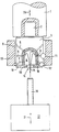
- the invention is explained in more detail using an application example shown in the accompanying drawing. It shows: The figure, a schematic representation of the units for carrying out the method according to the invention for the internal supply of liquid to the cutting edges of a machining tool held at one end of a rotating and axially movable tool spindle.
- a tool spindle 1 of a machine tool is provided with an indicated tool holder 2, in which a tool body 3 is received in a known manner.
- the tool body 3 is provided with an inner liquid space 4, from which radial and inclined channels 5, 6 and 7 e.g. lead to tool guide strips 8 and radial channels 9 and 10 to outlet openings in the immediate vicinity of the cutting edges of cutting elements of 11 and 12 for machining a workpiece 13.
- the tool body 3 is provided with an axial inlet opening 14 for a liquid jet 15, which is directed onto the tool body 3 from the side opposite the tool spindle 1.
- the liquid jet 15 is generated by a jet pipe 16, which is supplied with liquid under pressure in a conventional manner via a liquid device 17.
- the inner liquid space 4 in the tool body 3 can directly form the inlet opening, which is essentially acted upon by the liquid jet 15, so that a corresponding pressure build-up in the liquid space 4 is made possible.
- the inner liquid space 4 in the tool body 3 can, however, also be kept larger, in order, if necessary, to enable better connection to the various radial and inclined channels 5, 6, 7 and 9 and 10 and is then formed by a lower cover plate 18 with a funnel-shaped inlet opening 19 completed, which is again essentially applied by the liquid jet 15.
- the liquid jet 15 generated by the liquid device 17 via the jet pipe 16 can be provided by a stationary device or else the jet pipe 16 enables a telescopic shortening or the liquid device 17 makes a correspondingly controlled movement indicated by the double arrow 21.
- the method according to the invention can be used for a large number of machining operations which, as can be seen from the drawing, are aimed at machining through bores. Accordingly, cutter heads, milling heads, drilling tools and the like can be supplied with an internal liquid supply which is acted upon from the side opposite the tool spindle, as a result of which the expensive and wear-prone seals in hollow tool spindles for supplying the corresponding liquid flow, which have previously been accepted in such applications, can be avoided.
Landscapes
- Engineering & Computer Science (AREA)
- Mechanical Engineering (AREA)
- Auxiliary Devices For Machine Tools (AREA)
Applications Claiming Priority (2)
| Application Number | Priority Date | Filing Date | Title |
|---|---|---|---|
| DE3808707A DE3808707C1 (enExample) | 1988-03-16 | 1988-03-16 | |
| DE3808707 | 1988-03-16 |
Publications (2)
| Publication Number | Publication Date |
|---|---|
| EP0404793A1 EP0404793A1 (de) | 1991-01-02 |
| EP0404793B1 true EP0404793B1 (de) | 1993-12-29 |
Family
ID=6349832
Family Applications (1)
| Application Number | Title | Priority Date | Filing Date |
|---|---|---|---|
| EP89903129A Expired - Lifetime EP0404793B1 (de) | 1988-03-16 | 1989-03-15 | Verfahren zur innenzufuhr von kühl-, schmier- oder schneidmittel zu den schneidkanten oder führungsleisten eines sich drehenden bearbeitungswerkzeuges |
Country Status (3)
| Country | Link |
|---|---|
| EP (1) | EP0404793B1 (enExample) |
| DE (2) | DE3808707C1 (enExample) |
| WO (1) | WO1989008534A1 (enExample) |
Families Citing this family (5)
| Publication number | Priority date | Publication date | Assignee | Title |
|---|---|---|---|---|
| DE4304515C2 (de) * | 1993-02-15 | 1997-01-30 | Siemens Ag | Für hochtourigen Antrieb geeignetes, in Rotation versetzbares zahnärztliches Fräserwerkzeug |
| DE4401756A1 (de) * | 1994-01-21 | 1995-07-27 | Giddings & Lewis Gmbh | Verfahren und Vorrichtung zum Zuführen von Kühlschmiermittel |
| AT1324U1 (de) * | 1995-10-11 | 1997-03-25 | Plansee Tizit Gmbh | Werkzeug mit innenliegender kühlmittelzufuhr |
| US9114492B2 (en) * | 2011-10-07 | 2015-08-25 | Ahhneu-Ellsworth Limited Liability | Coolant supply for a machine tool |
| AT513785B1 (de) * | 2012-12-21 | 2016-01-15 | Wfl Millturn Tech Gmbh & Co Kg | Verfahren zum Bearbeiten eines an einer Werkzeugmaschine eingespannten hohlen Werkstücks |
Family Cites Families (7)
| Publication number | Priority date | Publication date | Assignee | Title |
|---|---|---|---|---|
| DE486635C (de) * | 1929-11-22 | Herbert Lindner | Vorrichtung zum Zufuehren von Kuehlwasser durch die Poren der Schleifscheibe | |
| CH141459A (de) * | 1929-01-18 | 1930-07-31 | Leya A G Maschbau | Schleifmaschine, insbesondere zum Schleifen von Hobelmessern. |
| GB832112A (en) * | 1957-10-18 | 1960-04-06 | Anderson Grice Company Ltd | Improvements in or relating to saws for stones or like hard material |
| US3156274A (en) * | 1961-07-27 | 1964-11-10 | Alexander J Golick | Mist lubricated ripsawing method and mechanisms |
| DE3003858C2 (de) * | 1980-02-02 | 1984-08-02 | Krebs & Riedel Kg Schleifscheibenfabrik, 3522 Bad Karlshafen | Vorrichtung zum Aufspannen und Kühlen eines Sägeblattes |
| DE3030792A1 (de) * | 1980-08-14 | 1982-03-11 | Hans Klaus 8091 Ebrach Schneider | Nassschleifvorrichtung |
| DE3241208A1 (de) * | 1982-11-08 | 1984-05-10 | Wekon Heinz Schnedler KG Werkzeug- u. Vorrichtungsbau, 6365 Rosbach | Werkzeugmaschine |
-
1988
- 1988-03-16 DE DE3808707A patent/DE3808707C1/de not_active Expired
-
1989
- 1989-03-15 EP EP89903129A patent/EP0404793B1/de not_active Expired - Lifetime
- 1989-03-15 WO PCT/EP1989/000275 patent/WO1989008534A1/de not_active Ceased
- 1989-03-15 DE DE89903129T patent/DE58906594D1/de not_active Expired - Fee Related
Also Published As
| Publication number | Publication date |
|---|---|
| DE3808707C1 (enExample) | 1989-10-12 |
| EP0404793A1 (de) | 1991-01-02 |
| DE58906594D1 (de) | 1994-02-10 |
| WO1989008534A1 (fr) | 1989-09-21 |
Similar Documents
| Publication | Publication Date | Title |
|---|---|---|
| DE69901004T2 (de) | Verfahren und vorrichtung zur bearbeitung von vorbearbeiteten, verzahnten werkstücken wie zahnräder | |
| DE4019661C2 (de) | Kühlschmiermittelversorgungseinrichtung | |
| DE2651879C2 (de) | Einrichtung zum Zuführen von Kühlmittel zur Innenseite einer topfförmigen Stirnschleifscheibe | |
| EP0229909B1 (de) | Tiefbohrmaschine | |
| EP0034659A1 (de) | Steuereinrichtung für den Bearbeitungsdruck an Läpp-, Hon- und Schleifmaschinen | |
| DE3306246A1 (de) | Verfahren und vorrichtung zur feinschleifbearbeitung an einem werkstueck mit einer duennen bearbeitungswand | |
| DE4211348C2 (de) | Energieführungsleitung an einer Werkzeugmaschine mit einem Drehtisch | |
| EP0404793B1 (de) | Verfahren zur innenzufuhr von kühl-, schmier- oder schneidmittel zu den schneidkanten oder führungsleisten eines sich drehenden bearbeitungswerkzeuges | |
| EP0237790B1 (de) | Honeinrichtung | |
| DE3120465A1 (de) | Saegenschaerfmaschine | |
| DE2517759A1 (de) | Mehrspindeldrehautomat | |
| DE2030851B2 (de) | Maschine zum Schleifen von mit einer Planschulter versehenen zylindrischen Werkstückbohrungen | |
| DE3639584A1 (de) | Nachbearbeitungsvorrichtung fuer schleifscheiben | |
| DE3811784A1 (de) | Abrichtrolle und verfahren zum abrichten einer schleifmaschine | |
| DE102020120636B3 (de) | Mehrfach-Halter für Werkzeuge und Verfahren dazu | |
| DE19623507C1 (de) | Drehendes Schneidwerkzeug mit Wechselmesser | |
| DE2540942C3 (de) | Honvorrichtung | |
| DE10322991A1 (de) | Verfahren und Vorrichtung zum Schleifen eines Werkstücks | |
| DE19836348C5 (de) | Werkzeugaufnahme für eine CNC-gesteuerte Hartdrehmaschine | |
| DE1176880B (de) | Pneumatische Lehre an Praezisions-schleifmaschinen | |
| DE3015344C2 (enExample) | ||
| DE2633493C2 (de) | Fräseinrichtung | |
| DE732012C (de) | Mittels Pressluft angetriebene Bohrmaschine | |
| DE2429928C3 (de) | Fräseinrichtung zum Bearbeiten von Kanten von Werkstücken, insbe andere von Spanplatten iiit harten Beschichtungen | |
| DD205370A1 (de) | Verfahren und einrichtung zur positionierung des abrichters einer innenrundschleifmaschine |
Legal Events
| Date | Code | Title | Description |
|---|---|---|---|
| PUAI | Public reference made under article 153(3) epc to a published international application that has entered the european phase |
Free format text: ORIGINAL CODE: 0009012 |
|
| 17P | Request for examination filed |
Effective date: 19891025 |
|
| AK | Designated contracting states |
Kind code of ref document: A1 Designated state(s): BE DE FR GB IT NL SE |
|
| 17Q | First examination report despatched |
Effective date: 19920330 |
|
| GRAA | (expected) grant |
Free format text: ORIGINAL CODE: 0009210 |
|
| AK | Designated contracting states |
Kind code of ref document: B1 Designated state(s): BE DE FR GB IT NL SE |
|
| PG25 | Lapsed in a contracting state [announced via postgrant information from national office to epo] |
Ref country code: IT Free format text: LAPSE BECAUSE OF FAILURE TO SUBMIT A TRANSLATION OF THE DESCRIPTION OR TO PAY THE FEE WITHIN THE PRE;WARNING: LAPSES OF ITALIAN PATENTS WITH EFFECTIVE DATE BEFORE 2007 MAY HAVE OCCURRED AT ANY TIME BEFORE 2007. THE CORRECT EFFECTIVE DATE MAY BE DIFFERENT FROM THE ONE RECORDED.SCRIBED TIME-LIMIT Effective date: 19931229 Ref country code: BE Effective date: 19931229 Ref country code: NL Effective date: 19931229 Ref country code: SE Effective date: 19931229 |
|
| ET | Fr: translation filed | ||
| REF | Corresponds to: |
Ref document number: 58906594 Country of ref document: DE Date of ref document: 19940210 |
|
| GBT | Gb: translation of ep patent filed (gb section 77(6)(a)/1977) |
Effective date: 19940114 |
|
| REG | Reference to a national code |
Ref country code: GB Ref legal event code: 746 Effective date: 19940217 |
|
| NLV1 | Nl: lapsed or annulled due to failure to fulfill the requirements of art. 29p and 29m of the patents act | ||
| PLBE | No opposition filed within time limit |
Free format text: ORIGINAL CODE: 0009261 |
|
| STAA | Information on the status of an ep patent application or granted ep patent |
Free format text: STATUS: NO OPPOSITION FILED WITHIN TIME LIMIT |
|
| 26N | No opposition filed | ||
| REG | Reference to a national code |
Ref country code: FR Ref legal event code: ST |
|
| REG | Reference to a national code |
Ref country code: FR Ref legal event code: RN |
|
| REG | Reference to a national code |
Ref country code: FR Ref legal event code: FC |
|
| REG | Reference to a national code |
Ref country code: FR Ref legal event code: D6 |
|
| REG | Reference to a national code |
Ref country code: FR Ref legal event code: CD Ref country code: FR Ref legal event code: TP |
|
| REG | Reference to a national code |
Ref country code: GB Ref legal event code: IF02 |
|
| PGFP | Annual fee paid to national office [announced via postgrant information from national office to epo] |
Ref country code: FR Payment date: 20050302 Year of fee payment: 17 |
|
| REG | Reference to a national code |
Ref country code: FR Ref legal event code: CA Ref country code: FR Ref legal event code: CD |
|
| PGFP | Annual fee paid to national office [announced via postgrant information from national office to epo] |
Ref country code: GB Payment date: 20060206 Year of fee payment: 18 |
|
| PGFP | Annual fee paid to national office [announced via postgrant information from national office to epo] |
Ref country code: DE Payment date: 20060330 Year of fee payment: 18 |
|
| GBPC | Gb: european patent ceased through non-payment of renewal fee |
Effective date: 20070315 |
|
| REG | Reference to a national code |
Ref country code: FR Ref legal event code: ST Effective date: 20071130 |
|
| PG25 | Lapsed in a contracting state [announced via postgrant information from national office to epo] |
Ref country code: DE Free format text: LAPSE BECAUSE OF NON-PAYMENT OF DUE FEES Effective date: 20071002 |
|
| PG25 | Lapsed in a contracting state [announced via postgrant information from national office to epo] |
Ref country code: GB Free format text: LAPSE BECAUSE OF NON-PAYMENT OF DUE FEES Effective date: 20070315 |
|
| PG25 | Lapsed in a contracting state [announced via postgrant information from national office to epo] |
Ref country code: FR Free format text: LAPSE BECAUSE OF NON-PAYMENT OF DUE FEES Effective date: 20070402 |
|
| PG25 | Lapsed in a contracting state [announced via postgrant information from national office to epo] |
Ref country code: FR Free format text: LAPSE BECAUSE OF NON-PAYMENT OF DUE FEES Effective date: 20060331 |