EP0403979A2 - Anorganischer ausgehärteter Formkörper und Verfahren zu dessen Herstellung - Google Patents
Anorganischer ausgehärteter Formkörper und Verfahren zu dessen Herstellung Download PDFInfo
- Publication number
- EP0403979A2 EP0403979A2 EP90111348A EP90111348A EP0403979A2 EP 0403979 A2 EP0403979 A2 EP 0403979A2 EP 90111348 A EP90111348 A EP 90111348A EP 90111348 A EP90111348 A EP 90111348A EP 0403979 A2 EP0403979 A2 EP 0403979A2
- Authority
- EP
- European Patent Office
- Prior art keywords
- inorganic
- blades
- cutter
- mold
- shape
- Prior art date
- Legal status (The legal status is an assumption and is not a legal conclusion. Google has not performed a legal analysis and makes no representation as to the accuracy of the status listed.)
- Withdrawn
Links
Images


Classifications
-
- B—PERFORMING OPERATIONS; TRANSPORTING
- B28—WORKING CEMENT, CLAY, OR STONE
- B28B—SHAPING CLAY OR OTHER CERAMIC COMPOSITIONS; SHAPING SLAG; SHAPING MIXTURES CONTAINING CEMENTITIOUS MATERIAL, e.g. PLASTER
- B28B11/00—Apparatus or processes for treating or working the shaped or preshaped articles
- B28B11/08—Apparatus or processes for treating or working the shaped or preshaped articles for reshaping the surface, e.g. smoothing, roughening, corrugating, making screw-threads
-
- B—PERFORMING OPERATIONS; TRANSPORTING
- B28—WORKING CEMENT, CLAY, OR STONE
- B28B—SHAPING CLAY OR OTHER CERAMIC COMPOSITIONS; SHAPING SLAG; SHAPING MIXTURES CONTAINING CEMENTITIOUS MATERIAL, e.g. PLASTER
- B28B7/00—Moulds; Cores; Mandrels
- B28B7/10—Moulds with means incorporated therein, or carried thereby, for ejecting or detaching the moulded article
-
- B—PERFORMING OPERATIONS; TRANSPORTING
- B28—WORKING CEMENT, CLAY, OR STONE
- B28B—SHAPING CLAY OR OTHER CERAMIC COMPOSITIONS; SHAPING SLAG; SHAPING MIXTURES CONTAINING CEMENTITIOUS MATERIAL, e.g. PLASTER
- B28B11/00—Apparatus or processes for treating or working the shaped or preshaped articles
- B28B11/12—Apparatus or processes for treating or working the shaped or preshaped articles for removing parts of the articles by cutting
-
- B—PERFORMING OPERATIONS; TRANSPORTING
- B28—WORKING CEMENT, CLAY, OR STONE
- B28B—SHAPING CLAY OR OTHER CERAMIC COMPOSITIONS; SHAPING SLAG; SHAPING MIXTURES CONTAINING CEMENTITIOUS MATERIAL, e.g. PLASTER
- B28B11/00—Apparatus or processes for treating or working the shaped or preshaped articles
- B28B11/14—Apparatus or processes for treating or working the shaped or preshaped articles for dividing shaped articles by cutting
-
- B—PERFORMING OPERATIONS; TRANSPORTING
- B28—WORKING CEMENT, CLAY, OR STONE
- B28B—SHAPING CLAY OR OTHER CERAMIC COMPOSITIONS; SHAPING SLAG; SHAPING MIXTURES CONTAINING CEMENTITIOUS MATERIAL, e.g. PLASTER
- B28B17/00—Details of, or accessories for, apparatus for shaping the material; Auxiliary measures taken in connection with such shaping
- B28B17/0018—Separating articles from each other
-
- B—PERFORMING OPERATIONS; TRANSPORTING
- B28—WORKING CEMENT, CLAY, OR STONE
- B28B—SHAPING CLAY OR OTHER CERAMIC COMPOSITIONS; SHAPING SLAG; SHAPING MIXTURES CONTAINING CEMENTITIOUS MATERIAL, e.g. PLASTER
- B28B3/00—Producing shaped articles from the material by using presses; Presses specially adapted therefor
- B28B3/02—Producing shaped articles from the material by using presses; Presses specially adapted therefor wherein a ram exerts pressure on the material in a moulding space; Ram heads of special form
- B28B3/021—Ram heads of special form
-
- B—PERFORMING OPERATIONS; TRANSPORTING
- B28—WORKING CEMENT, CLAY, OR STONE
- B28B—SHAPING CLAY OR OTHER CERAMIC COMPOSITIONS; SHAPING SLAG; SHAPING MIXTURES CONTAINING CEMENTITIOUS MATERIAL, e.g. PLASTER
- B28B3/00—Producing shaped articles from the material by using presses; Presses specially adapted therefor
- B28B3/12—Producing shaped articles from the material by using presses; Presses specially adapted therefor wherein one or more rollers exert pressure on the material
- B28B3/123—Producing shaped articles from the material by using presses; Presses specially adapted therefor wherein one or more rollers exert pressure on the material on material in moulds or on moulding surfaces moving continuously underneath or between the rollers, e.g. on an endless belt
Definitions
- This invention relates to an inorganic cured shape which is used as, for example, roofing, exterior walls, and interior walls, and a method for producing the same.
- inorganic cured materials used in roofing, exterior walls and interior materials have been produced from a water-curable inorganic composition mainly comprising cement, gypsum, and the like, which is molded by sheeting, extrusion molding, semi-dry molding, or the like, with or without subsequent pressure molding, to obtain an inorganic molding, which is further divided or cut into desired shapes, and then cured.
- a water-curable inorganic composition mainly comprising cement, gypsum, and the like, which is molded by sheeting, extrusion molding, semi-dry molding, or the like, with or without subsequent pressure molding, to obtain an inorganic molding, which is further divided or cut into desired shapes, and then cured.
- a first method for producing inorganic cured shapes by pressure molding a mixture comprising a water-curable inorganic composition by means of a molding die to obtain an inorganic molded material, and hardening and curing the inorganic molded material characterized in that at least a portion of the molding die contacting the material is air-permeable and, prior to hardening and curing the inorganic molded material, air is passed through the air-permeable material to an interface between the material and the portion of the molding die contacting the material, whereby the inorganic molded material is released from the molding die.
- a second method for producing inorganic cured shapes by pressure molding a mixture comprising a water-curable inorganic composition by means of a molding die, and hardening and curing the inorganic molded material characterized in that, prior to hardening and curing the inorganic molded material, a pattern is provided on the surface of the inorganic molded material as needed, the mixture is pressure molded using a molding die having a projection to form a diagonal cut edge, and the inorganic molded material is cut using a cutter along a groove formed by a projection of the molding die.
- a pusher movable in the slit in the moving direction of the blades and having nearly the same size as the blades in the width direction of the slit, which ejects cutting debris by movement of the pusher in the slit.
- a cutter blade unit is used which has blades arranged in two rows along the longitudinal direction of the slit removal portion, the blades being offset from each other across the two rows of blades.
- a fifth method for producing inorganic cured shapes by pressure molding a mixture comprising a water-curable inorganic composition by means of a molding die to obtain an inorganic molded material, and hardening and curing the inorganic molded material characterized in that, prior to hardening and curing the inorganic molded material, a plurality of holes or grooves is discontinuously formed in the inorganic molded material along a boundary between a slit removal portion and a main portion of the inorganic molded material to form a slit, by cutting one of two rows of the boundary along the longitudinal direction of the slit removal portion using one of cutter blade units, and then cutting the other of the two rows of the boundary using the other of the cutter blade units.
- a first inorganic cured shape produced by pressure molding and curing a mixture comprising a water-curable inorganic composition, having grooves for fracture formed on the surface of the inorganic cured shape.
- a second inorganic cured shape produced by pressure molding and curing a mixture comprising a water-curable inorganic composition, having an integral slit removal portion adapted to form a slit in at least part of the inorganic cured shape, and a plurality of holes or grooves discontinuously formed in the inorganic molded material along a boundary between the slit removal portion and a main portion of the inorganic cured shape.
- the inorganic cured shapes refer to shapes such as those used in roofing, for exterior walls, and as interior materials, which are produced from a water-curable inorganic composition comprising cement and gypsum as main raw materials.
- the composition may be mixed as needed with silica-based material, a lime-based material, a reinforcing materials, aggregates, water-reducing agents, thickening agents, and the like, and is extrusion molded into a green sheet.
- it may be in the form of a kneaded material, directly press molded by a molding die to obtain the inorganic molded material, which is then hardened and cured.
- the mixed and kneaded material of the present invention refers to a material obtained by adding water in an appropriate amount to the water-hardenable inorganic composition, formed by various methods.
- the porous material of which the portion of the molding die contacting the green sheet is composed comprises mainly sintered powder, resulting in an aggregate having numerous capillaries communicating with each other.
- the porous material includes air- permeable ceramics, metal fine powders, and air-permeable sintered metals.
- the air-permeable material for example; an air-permeable sintered ceramic, is obtained by mixing a ceramic powder with a metal powder and a fiber, followed by sintering.
- a Suitable air-permeable sintered metal is obtained by firing bronze or stainless steel powder. Both of these materials contain numerous pores 1 to 25 ⁇ m in size formed during the firing process, which allow air to pass evenly, and can be further provided with fine patterns such as stone grain or wood grain on the die surface, which can be precisely transferred to the molded products.
- the air-permeable sintered metal can be welded to other metals and is thus superior in processability to the air-permeable sintered ceramic.
- the molding die used in the present invention provides shaping and/or patterning of the water-hardenable inorganic composition, or a green sheet which is primarily formed into a plate after kneading.
- the kneaded material can be used in press molding processes such as flat pressing and roll pressing of ceramic materials.
- the portion of the molding die contacting the kneaded material is the portion which closely and directly contacts the material to be molded to provide the inorganic molded material with a pattern or the like.
- the contacting portion at least in part, is composed of the air-permeable material, which is used in the press molding process.
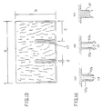
- Fig.1 and Fig.3(a) and 3(b) show examples of molding dies which use the air-permeable material.
- Fig.1 is a schematic cross sectional view showing a molding die used in the flat pressing process.
- Fig.3(a) is a schematic view showing a molding die used in the roll pressing process, and
- Fig.3(b) is a schematic cross sectional view of the die.
- a molding die 10 comprises a green sheet contacting portion 12 which contacts a green sheet 11 and is made of the air-permeable material.
- An air chamber covers the entire green sheet contacting portion 12, and an air supply unit 15 introduces air into the air chamber 13 through a supply pipe 14, whereby the green sheet 11 which is transported by elevating means (not shown) is press molded.
- Fig.2 is a schematic view showing the air-permeable material used in the green sheet contacting portion 12.
- This material is an aggregate of capillaries 17 formed by sintering, and air can be freely supplied through pores 18 of the capillaries 17.
- air can be supplied to air chamber 13 simultaneously with - or a little before - the completion of pressing to supply air to contact interface 16 between green sheet contacting portion 12 and green sheet 11, thereby releasing green sheet 11.
- the air pressure depends on the raw material and can be appropriately set according to the release condition of the material to be molded.
- the molding die using the inventive air-permeable material in the kneaded material contacting portion has good releasability with less tendency of the molded material to adhere to the die, and has the following additional advantages:
- a press molding process using the roll pressing method will now be described with reference to Fig.3.
- a roll- formed green sheet contacting portion 21 of a molding die 20, rotatably mounted on ball bearings 19, is provided with a relief pattern, and is made of the air-permeable material.
- Cylindrical pipe-formed air chamber 22, which rotatably supports the green sheet contacting portion on the ball bearings 19 is provided with slit 25 formed in the axial direction of the air chamber 22 to supply air to a contact interface 24 between green sheet 23 and green sheet contacting portion 21 (Fig.3(b)).
- Air chamber 22 is connected with air supply pipe 26, through which air is supplied from air supply unit 27 (Fig.3(c)).
- the molding die using the inventive air-permeable material is not limited to the configuration of the above example, but the air-permeable material can be used in any portion of the die which contacts the inorganic molded material such as the green sheet or the kneaded material.
- the air-permeable material can be used in any portion of the die which contacts the inorganic molded material such as the green sheet or the kneaded material.
- green sheet contacting portions of both die portions can be made of the air-permeable material, thereby preventing the molded material from adhering to either die and achieving a remarkably improved releasability.
- a second embodiment of the method for the production of the inorganic cured shapes according to the present invention in which an inorganic molded material prior to hardening and curing is molded and cut, will now be described. Parts and components which are the same as those used in the first configuration are indicated by the same names and detailed description thereof is omitted.
- the molding die used in the present invention is one which is shown in Fig. 8, in which molding die 41 has on its inner surface 41a a relief pattern to form a pattern on the resulting inorganic molded material and to form the molded material into a predetermined shape.
- Fig.8 is a perspective back view of the molding die, which is placed upside down in use to press against the green sheet.
- the projection is a ridge-formed projection provided on the molding die to form a diagonal cut edge in the molded material.
- a projected portion 42 is formed so that a portion of molding die 41 is tapered.
- the groove in the present invention refers to a portion such as groove 44a or step 44b formed in the kneaded material by the projection of the molding die, which is cut by a cutter.
- the cutter used in the present invention is one which is used to cut the inorganic molded material press formed by the molding die, for example, as shown in Fig.9(d),
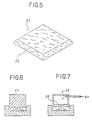
- the green sheet 43, formed by molding die 41, is cut using blades 46 of cutter 45 along groove 44a or step 44b to obtain inorganic molded material 33 having diagonal cut edge 32, as shown in Fig.5.
- the kneaded material is first press molded using the molding die having the projection and is then cut by the cutter along the groove formed in the kneaded material by the projection, there is no problem of cutting difficulty or the occurrence of crack 49 as seen in the prior art method in which, for example, as shown in Fig. 10, green sheet 48 is cut and patterned using molding die 47 having acute-angled cutting projection 47a.
- a third embodiment of the method for the production of the inorganic cured shapes of the present invention, in which a slit portion is formed in the inorganic molded material prior to hardening and curing, will now be described.
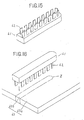
- cutter 50 with a pusher used in the present invention comprises a pair of parallel blades 51a and 51b, slit 52 formed by blades 51a and 51b, pusher 53 which is movable within slit 52 in the pushing direction (downward in the Figure) of blades 51a and 51b and having almost the same length as blades 51a and 51b in the width direction, and actuator 55 to render pusher 53 movable in the vertical direction through shaft 54.
- the cutter moves vertically to cut part of an inorganic molded material to form slit portion 57 as shown in Fig. 13.
- Actuator 55 can be an air cylinder, a coil spring, an oil cylinder, or the like.
- Pusher 53 in slit 52 is preferably located at a position where it is not contacted by the cut material and is preferably made of a hard substance which does not readily deform, such as metal or plastic.
- the position of pusher 53 may be the same as the blade tips since the cylinder is withdrawn when the material is put in the slit.
- cutter 50 having the pusher will now be described with reference to Figs. 12(a) to 12(d).
- the cutting process can be repeated without any changes in the dimensions of blades 59a and 59b or damage to blade 60 due to cutting debris 58, as is seen in the prior art method as shown in Figs. 14(a) to 14(c).
- a fourth embodiment of the method for the production of the inorganic cured shapes of the present invention in which a slit portion is formed in the inorganic cured shape prior to hardening and curing, will now be described.
- cutter blade unit 61 comprises blades 62 in two parallel rows along boundary Z between main portion 63a and slit removal portion 63b of inorganic molded material 63; the unit is peripherally disposed so that blades 62 are offset from each other.
- a first slit formation method according to the present invention to form slit portion 64 in inorganic molded material 63 will now be described with reference to Fig. 16 through Fig. 18.
- Holes 65 are elongated, but the shape of holes 65 is not limited to this; but, for example, may be formed as fine circular perforations 66 as shown in Figs. 19(a) and (b).
- the holes 65 for slit formation formed in the inorganic molded material are through holes.
- inorganic molded material 63 may be provided with a plurality of grooves 67 discontinuously formed, and slit removal portion 63b surrounded by grooves 67 is removed to form the slit portion.
- the above-described first slit formation method is one in which intermittent holes 65 are formed along boundary Z between main portion 65a and slit removal portion 63b of inorganic molded material 63 by a single punching.
- FIG. 21 A second slit formation method according to the present invention will now be described with reference to Figs. 21 through 25.
- This method uses a pair of cutter blade units 68a and 68b, each of which has a single row of blades 62 along boundary Z between main portion 63a and slit removal portion 63b of inorganic molded material 63.
- slit portion 64 may be formed as follows. Using continuous blades, one side of the blades is driven in along boundary Z to form slot 69 (Fig.26(a)), the other side is driven in to form slot 69 (Fig.26(b)), and slit removal portion 63b surrounded by slots 69 is punched out to form slit portion 64 as shown in Fig.26(c).
- the holes may alternatively formed as grooves.
- Fig.27 is a schematic perspective view of an example of an inorganic cured shape according to the present invention
- Fig.28 is a schematic cross sectional view thereof.
- inorganic cured shape 70 is provided on its surface with grooves 71 for cutting.
- the inorganic cured shape, prior to use, is cut along grooves 71 to obtain three pieces 72a, 72b, and 72c.
- Cutting grooves 71 formed in the inorganic cured shape have acute-angled cutting portions 73 as shown in Fig. 28, and can be readily broken by only a single impact along grooves 71. It is preferable to form cutting grooves 71 in inorganic cured shape 70 at the time the shape is pressure molded.
- the plurality of pieces 72a to 72c in the form adapted to actual use, can be molded, painted, packaged, and shipped at one time, thereby considerably improving their handling efficiency.
- the inorganic cured shape is molded in a large size, and cut only when needed, thereby remarkably improving construction efficiency.
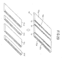
- Fig.29 is a schematic perspective view of another embodiment of the inorganic cured shape according to the present invention
- Fig.30 is a cross sectional view thereof.
- inorganic cured shape 70 is provided on its upper surface with three cutting grooves 71, which can be cut to obtain four pieces 72a, 72b, 72c, and 72d.
- groove 71 has cut-in 73 which functions to facilitate cutting.
- Pieces 72a through 72d have differently shaped longitudinal side surfaces 74a and 74b, one side surface 74a being stepped, whereas other side surface 74b is flat, for a pleasing appearance.
- Cement ordinary Portland cement (from Onoda Cement, Blaine specific surface area: 3,300 cm2/g) Quartzite powder: (from Chichibu Kogyo, Blaine specific surface area: 3,800 cm2) Wollastonite: (tradename: Mighty 150 from Kao, a polycondensation product of naphthalene sulfonate salt) Thickener: (tradename: Metholose 90SH-15000, from Shin-Etsu Chemical) Fiber: Polypropylene (P.P.): (tradename: Toughlite, from Teikoku Sangyo, fiber length: 6 mm) Table 1 Composition (part by weight) Fiber Cement Quartzite powder Wollastonite Water Thickener Water reducing agent P.P. 1.6 100 15 45 40 0.8 3
- Predetermined amounts of the powder and fiber were dry mixed in a mixer for approx. 3 min, and then wet mixed with water for approx. 10 min. Then, using an extrusion molding machine, the mixture was extrusion molded to a width of 250 mm and a thickness of 9 mm, followed by press molding to obtain an inorganic molded material with a thickness of 8 mm.
- green sheet 30 was pressure molded using molding die 29 having green sheet contacting portion 28 comprising an air-permeable material, and cut by cutter 31 shown in Fig.4(d) to obtain inorganic molded material 33 having diagonally press cut edge 32 and a stone-grained surface.
- the molded material was steam cured (at 60°C for 24 hours), wet room cured at 20°C for one week as secondary curing, and then dried at 105°C until completely dry to obtain the inorganic cured shape.
- the thus obtained inorganic molded material 33 had stone-grained pattern sharply transferred onto the surface.
- a good result was also obtained when projection 34 was provided on molding die 29 to form a deep pattern and a diagonal cut edge, with no adherence of the material to the die.
- Kneaded materials were prepared using the following raw materials in the compositions and at molding pressures shown in Table 2.
- No.1 is an example which has an increased water ratio and low thickener content to confer fluidity on the raw materials.
- No.2 is an example which has an increased thickener content to confer plasticity on the raw materials.
- Cement ordinary Portland cement Sand: Toyoura standard sand Fiber: polypropylene fiber, 6 mm long
- Thickener methylcellulose
- Kneaded materials of the above compositions were put into the molding die shown in Fig.7 and pressure molded with a male die having a deep pattern to obtain inorganic molded materials.
- male die 37 shown in Fig.6 made of metal, male die 38 shown in Fig.7 made of air-permeable material 39, and a sintered ceramic (tradename: Porceramics, from Shinto Kogyo) die were individually tested for adhesion of the kneaded material to the die.
- compressed air was supplied by an air compressor to the die after the predetermined molding was effected and immediately before releasing the pressure.
- the air-permeable material when used in the die, even high water-ratio materials or high-viscosity materials could be readily released from the die, without adherence of the materials.
- the green sheet material can be readily released from the molding die without adherence to the die during molding prior to hardening and curing.
- the present invention provides an improved releasability of the molded materials from the die.
- An inorganic molded material was obtained using the same procedure as in Embodiment 1.
- green sheet 43 was pressure molded using molding die 41 having projections 42, and then cut by cutter 15 to obtain a stone-grained inorganic molded material 33 having diagonally cut edges 32 as shown in Fig.5.
- molded material 33 was steam cured at 60°C for 24 hours, wet room cured at 20°C for one week as secondary curing, and then dried until completely dry to obtain the inorganic cured shape.
- inorganic molded material 33 had a stone-grained pattern sharply transferred onto its surface. A good result was obtained, since molding die 41 had projections 42 to provide patterns and diagonally cut edges; then, inorganic molded material 33 was cut by cutter 45, with no cracking noted.
- the inorganic molded material can be cut to have diagonally cut edges without causing any anomalies such as cracking during cutting.
- An inorganic molded material was obtained using the same procedure as in Embodiment 1.
- cutter 50 shown in Fig.11 was used to form two slit portions 57 having a width of 4 mm in part of the inorganic molded material.
- the molded material was steam cured at 60°C for 24 hours, and wet room cured at 20°C for one week as secondary curing to obtain a tile (dimensions: a: 450 mm, b: 300 mm, c: 150 mm) having the two slit portions 57 as shown in Fig.13.
- the above cutting process alone was repeated using cutter 50, but there were noted no changes in dimensions or damages to the cutter blades.
- the present invention eliminates clogging of cutting debris between the blades and changes in dimensions and damage to the blades, thereby extending their service life; it is able to form the slit portions with no variations in dimensions for an extended period of use.
- An inorganic molded material was obtained using the same procedure as in Embodiment 1.
- Two cutter blade units 61 shown in Fig. 15 were used to form intermittent holes 65 along boundary Z in part of inorganic molded material 63.
- Inorganic molded material 63 was then cut into predetermined dimensions. After molding and cutting, the molded material was steam cured at 60°C for 24 hours, and wet room cured at 20°C for one week as secondary curing. Then, slit removal portion 63b surrounded by holes 65 was punched out to form slit portion 64, obtaining a tile having two slit portions 57 as shown in Fig. 13 (dimensions: a: 450 mm, b: 300 mm, c: 150 mm). The above cutting process alone was repeated using one and the same cutter, and no changes in dimensions or damages to the cutter blades were noted.
- the present invention eliminates clogging of cutting debris between the blades as well as changes in dimensions or damage to the blades; these are otherwise seen in prior art slit formation. Thereby the service life of the blades was extended, and they are able to form the slit portions with no variations in dimensions for an extended period of use.
- Predetermined amounts of the powders and fiber were dry mixed in a mixer for approx. 3 min, and then wet mixed with water for approx. 10 min. Thereafter, using an extrusion molding machine, the mixture was extrusion molded to a width of 400 mm and a thickness of 9 mm, and then press molded in a flat press (100 t) under a pressure of 10 kg/cm2 to obtain an inorganic molded material with a thickness of 8 mm.
- the inorganic molded material was given a single cutting groove 71 as shown in the cross sectional view of Fig. 28. Then, the inorganic molded material was cut into a predetermined size, steam cured at 60°C for 24 hours, and wet air cured at 20°C for one week as secondary curing to obtain inorganic cured shape 75 having cutting groove 71 with cut-in 73.
- the inventive tiles When used in construction, the inventive tiles were easy to handle because they did not require carrying up piece by piece as is necessary with the prior art products. Furthermore, the cut face along groove 71 can be hidden by overlapping or sealing the tiles in construction, thereby assuring good appearance.
- the inorganic cured shapes according to the present invention are provided on their surfaces with cutting grooves, a plurality of pieces can be molded, painted, packaged, and shipped at one time, giving improved workability. Furthermore, the inventive inorganic cured shapes can be handled as an aggregate until immediately prior to use, at which time it is cut along the cutting grooves into pieces, thereby remarkably improving the construction efficiency.
Landscapes
- Engineering & Computer Science (AREA)
- Chemical & Material Sciences (AREA)
- Ceramic Engineering (AREA)
- Mechanical Engineering (AREA)
- Structural Engineering (AREA)
- Manufacturing & Machinery (AREA)
- Devices For Post-Treatments, Processing, Supply, Discharge, And Other Processes (AREA)
- Press-Shaping Or Shaping Using Conveyers (AREA)
Applications Claiming Priority (10)
| Application Number | Priority Date | Filing Date | Title |
|---|---|---|---|
| JP154633/89 | 1989-06-19 | ||
| JP15463389A JPH0319804A (ja) | 1989-06-19 | 1989-06-19 | 無機質硬化体の製造方法 |
| JP190498/89 | 1989-07-25 | ||
| JP19049889A JPH0790540B2 (ja) | 1989-07-25 | 1989-07-25 | 無機質成形体の成形・切断方法 |
| JP19049789A JPH0355209A (ja) | 1989-07-25 | 1989-07-25 | 無機質成形体の裁断方法 |
| JP190497/89 | 1989-07-25 | ||
| JP1349490A JPH03218804A (ja) | 1990-01-25 | 1990-01-25 | 無機質成形体及び無機質成形体のスリット形成方法 |
| JP13494/90 | 1990-01-25 | ||
| JP1990005102U JPH085781Y2 (ja) | 1990-01-25 | 1990-01-25 | 無機質硬化体 |
| JP5102/90 | 1990-01-25 |
Publications (2)
| Publication Number | Publication Date |
|---|---|
| EP0403979A2 true EP0403979A2 (de) | 1990-12-27 |
| EP0403979A3 EP0403979A3 (de) | 1992-01-22 |
Family
ID=27518559
Family Applications (1)
| Application Number | Title | Priority Date | Filing Date |
|---|---|---|---|
| EP19900111348 Withdrawn EP0403979A3 (de) | 1989-06-19 | 1990-06-15 | Anorganischer ausgehärteter Formkörper und Verfahren zu dessen Herstellung |
Country Status (2)
| Country | Link |
|---|---|
| EP (1) | EP0403979A3 (de) |
| KR (1) | KR910000311A (de) |
Cited By (2)
| Publication number | Priority date | Publication date | Assignee | Title |
|---|---|---|---|---|
| BE1003082A5 (fr) * | 1987-01-06 | 1991-11-19 | Usg Interiors Inc | Procede et appareil de fabrication de carreaux ou panneaux acoustiques texturises. |
| CN114250094A (zh) * | 2022-01-02 | 2022-03-29 | 罗利芳 | 一种生物质燃料制备装置 |
Family Cites Families (5)
| Publication number | Priority date | Publication date | Assignee | Title |
|---|---|---|---|---|
| DE285341C (de) * | ||||
| US2733493A (en) * | 1956-02-07 | bryer | ||
| DE1205435B (de) * | 1961-05-10 | 1965-11-18 | Gottfried Cremer Dr | Verfahren zum kontinuierlichen Herstellen von duennwandigen Wandverkleidungsplatten aus keramischem Werkstoff und Tunnelofen zur Durchfuehrung des Verfahrens |
| FR1400411A (fr) * | 1964-03-03 | 1965-05-28 | Rieter Werke Haendle | Moule de pressage |
| US4413966A (en) * | 1981-06-26 | 1983-11-08 | Wallace Murray Corporation | Fluid-release mold and the method of manufacturing the same |
-
1990
- 1990-06-15 EP EP19900111348 patent/EP0403979A3/de not_active Withdrawn
- 1990-06-19 KR KR1019900009018A patent/KR910000311A/ko not_active Withdrawn
Cited By (3)
| Publication number | Priority date | Publication date | Assignee | Title |
|---|---|---|---|---|
| BE1003082A5 (fr) * | 1987-01-06 | 1991-11-19 | Usg Interiors Inc | Procede et appareil de fabrication de carreaux ou panneaux acoustiques texturises. |
| CN114250094A (zh) * | 2022-01-02 | 2022-03-29 | 罗利芳 | 一种生物质燃料制备装置 |
| CN114250094B (zh) * | 2022-01-02 | 2024-05-28 | 罗利芳 | 一种生物质燃料制备装置 |
Also Published As
| Publication number | Publication date |
|---|---|
| KR910000311A (ko) | 1991-01-29 |
| EP0403979A3 (de) | 1992-01-22 |
Similar Documents
| Publication | Publication Date | Title |
|---|---|---|
| EP1480799B1 (de) | Verfahren und vorrichtung zum herstellen von mauerblöcken mit gerauhter oberfläche | |
| EP0403979A2 (de) | Anorganischer ausgehärteter Formkörper und Verfahren zu dessen Herstellung | |
| DE60213749D1 (de) | Verfahren und Anlage zum Herstellen keramischer Fliesen und Platten | |
| US6234780B1 (en) | Vacuum osmosis and solidification forming machine | |
| EP2826608A1 (de) | Verfahren zum Formen von knetbarem Material und Form für knetbares Material | |
| GB2260318A (en) | An inorganic plate | |
| JPS6014686B2 (ja) | 凹溝を有する無機質板の製造法 | |
| JP3984333B2 (ja) | 無機質板の製造方法 | |
| JPH0355210A (ja) | 無機質成形体の成形・切断方法 | |
| EP1266733A2 (de) | Verfahren und Anlage zur Herstellung von keramischen Fliesen und Platten mit grossen Abmessungen | |
| JPH0319804A (ja) | 無機質硬化体の製造方法 | |
| EP1201382A3 (de) | Vorrichtung zum Herstellen von Fliesen aus zementartigen Mischungen | |
| JPH07214533A (ja) | レンガタイルの製造方法 | |
| JP2016141150A (ja) | 建築材の押出成型機に使用される金型及びその金型の製造方法 | |
| JPH0355207A (ja) | 無機質成形体の離型方法 | |
| JPS6023010A (ja) | 無石綿特殊無機質単板の製造法 | |
| JP2609193B2 (ja) | 二つ割タイルの製造方法 | |
| JP4473780B2 (ja) | 出隅役物用成形材料のプレス成形方法 | |
| JPH0660044B2 (ja) | 無機板状体の製造方法 | |
| SU1519879A1 (ru) | Способ формовани строительных изделий из бетонной смеси | |
| CN101708627A (zh) | 用于在陶瓷产品的表面上获得凹槽的方法及设备 | |
| CN101348373A (zh) | 蜂窝瓷砖的制造方法 | |
| JPH04292906A (ja) | 板状セメント製品の押出成形方法 | |
| JPH0618684B2 (ja) | 無機質建材の養生方法 | |
| JPS589730B2 (ja) | 水切り突条をもつ瓦の製法およびその水切り突条形成装置 |
Legal Events
| Date | Code | Title | Description |
|---|---|---|---|
| PUAI | Public reference made under article 153(3) epc to a published international application that has entered the european phase |
Free format text: ORIGINAL CODE: 0009012 |
|
| AK | Designated contracting states |
Kind code of ref document: A2 Designated state(s): BE CH DE DK ES FR GB IT LI |
|
| PUAL | Search report despatched |
Free format text: ORIGINAL CODE: 0009013 |
|
| AK | Designated contracting states |
Kind code of ref document: A3 Designated state(s): BE CH DE DK ES FR GB IT LI |
|
| 17P | Request for examination filed |
Effective date: 19920629 |
|
| 17Q | First examination report despatched |
Effective date: 19940630 |
|
| STAA | Information on the status of an ep patent application or granted ep patent |
Free format text: STATUS: THE APPLICATION IS DEEMED TO BE WITHDRAWN |
|
| 18D | Application deemed to be withdrawn |
Effective date: 19941111 |