EP0402842B1 - Vorrichtung zum Verdampfen von Substanzen - Google Patents
Vorrichtung zum Verdampfen von Substanzen Download PDFInfo
- Publication number
- EP0402842B1 EP0402842B1 EP90111049A EP90111049A EP0402842B1 EP 0402842 B1 EP0402842 B1 EP 0402842B1 EP 90111049 A EP90111049 A EP 90111049A EP 90111049 A EP90111049 A EP 90111049A EP 0402842 B1 EP0402842 B1 EP 0402842B1
- Authority
- EP
- European Patent Office
- Prior art keywords
- container
- tube
- vapor
- substance
- holes
- Prior art date
- Legal status (The legal status is an assumption and is not a legal conclusion. Google has not performed a legal analysis and makes no representation as to the accuracy of the status listed.)
- Expired - Lifetime
Links
Images



Classifications
-
- H—ELECTRICITY
- H01—ELECTRIC ELEMENTS
- H01S—DEVICES USING THE PROCESS OF LIGHT AMPLIFICATION BY STIMULATED EMISSION OF RADIATION [LASER] TO AMPLIFY OR GENERATE LIGHT; DEVICES USING STIMULATED EMISSION OF ELECTROMAGNETIC RADIATION IN WAVE RANGES OTHER THAN OPTICAL
- H01S3/00—Lasers, i.e. devices using stimulated emission of electromagnetic radiation in the infrared, visible or ultraviolet wave range
- H01S3/02—Constructional details
- H01S3/03—Constructional details of gas laser discharge tubes
- H01S3/031—Metal vapour lasers, e.g. metal vapour generation
Definitions
- the present invention relates to a substance vaporizing apparatus for generating a vapor of a substance to be used as an ionizing medium or an exciting medium and, more specifically, to a structure capable of functioning to vaporize a substance.
- Fig. 1 shows a conventional metal vapor laser as, for example, published in 6th Nenji Taikai Koen Yoko-shu, 21aIIB3, pp. 60-63 (1986). As shown in Fig.
- the metal vapor laser comprises discharge electrodes 1a and 1b, a cylindrical discharge tube 2 defining a discharge space 3 in which a metal vapor 5 produced by vaporizing metal pieces 4, such as copper pieces, is excited, a heat shield 6 formed of a heat-insulating material, such as wool, resonant mirrors 7a and 7b for laser oscillation, flanges 8a and 8b defining a sealed space including a vacuum chamber 9, an insulating tube 10, a sealing tube 11, a gas inlet port 12a, and a gas outlet port 12b.
- a pulse voltage is applied across the electrodes 1a and 1b to form a discharge within the discharge space 3, and then a buffer gas filling the discharge space 3 is heated by the energy of accelerated ions and electrons to vaporize the metal pieces 4.
- the ions and electrons accelerated by a pulse discharge and having high energy and high-temperature atoms of the heated buffer gas collide with the atoms of the vaporized metal and transfer their energy, so that the atoms of the vaporized metal is excited to a higher energy level.
- the heat shield 6 serves for maintaining the gas at a desired temperature to maintain a predetermined vapor density in the discharge space 3.
- the function of the vacuum chamber 9 is similar to that of the heat shield; the vacuum chamber 9 suppresses particularly convection heat loss. Light is emitted when the energy level of the atoms of the vaporized metal drops to a lower energy level or the ground energy level.
- the light thus emitted is amplified optically by the resonant mirrors 7a and 7b to emit a laser beam outside for industrial uses, such as laser machining.
- Fig. 2 shows the buffer gas temperature distribution and the vapor density distribution with respect to the diametrical and axial directions of the discharge space 3 in the metal vapor laser thus constructed.
- X-axis and Y-axis coincide respectively with the diametrical direction and the axial direction of the discharge space 3; temperature is measured upward on T-axis; indicated at 3a is the center axis of the discharge space 3 and at 3b are diametrically opposite ends of the discharge space.
- a curve l represented by a dotted line indicates temperature distribution with respect to the axial direction
- curves n1, n2 and n3 represented by alternate long and short dash line indicate vapor distribution with respect to the diametrical direction
- curves m1, m2 and m3 represented by continuous lines indicated temperature distribution with respect to the diametrical direction.
- the temperature of the buffer gas decreases from the central portion of the discharge space 3 around the center axis 3a toward the periphery of the discharge space 3 represented by the diametrically opposite ends 3b.
- the temperature of the buffer gas in the vicinity of the axial ends of the discharge space 3 is lower than that in the central portion of the same.
- a substance vaporizing apparatus for generating a vapor of a substance for use as an excited medium or an ionized medium in a vapor ion laser, wherein the vapor is generated by heating the substance in a container with holes in a gas-filled discharge tube.
- the substance vaporizing apparatus according to the invention is defined in independent claim 1. Preferable embodiments are defined in the dependent claims.
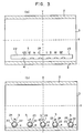
- Figs. 3(a) and 3(b) Shown in Figs. 3(a) and 3(b) is a substance vaporizing apparatus in a first embodiment according to the present invention.
- the substance vaporizing apparatus is provided with a container 22 provided with a plurality of through holes 24.
- the diameters of the through holes 24 nearer to the opposite ends of a discharge tube 2 are greater than those of the through holes 24 nearer to the middle of the discharge tube 2.
- the diameter of the through hole 24 at the middle of the container 22 is on the order of 0.5 mm, and that of the through hole 24 adjacent to the extremity of the container 22 is on the order of 2 mm. Therefore, the metal vapor emitting rate per unit length of the container 22 is lower in the middle portion of the discharge space 3 than in the end portions of the discharge space 3 where the gas temperature Tg gas is lower than that in the middle portion.
- the vapor density is distributed uniformly with respect to the axial direction of the discharge space 3, so that the laser oscillation efficiency per unit length is enhanced.
- the first embodiment has been described on an assumption that the gas temperature Tg in the middle portion of the discharge space 3 is the highest, but a portion where the gas temperature Tg is the highest is not necessarily the middle portion depending on the construction of the substance vaporizing apparatus and the mode of pulse discharge. In such a case, the distribution of the metal vapor emitting rate per unit length may be changed according to the axial distribution of the gas temperature Tg in the discharge tube 2.
- the substance vaporizing apparatus is provided with a plurality of spherical containers 22 respectively having through holes 24 of different diameters.
- the spherical containers 22 are arranged so that the metal vapor is emitted into the end portions of the discharge space 3 at a higher emitting rate per unit length and into the middle portion of the discharge space 3 at a lower emitting rate per unit length. It is also possible to distribute spherical containers 22 provided respectively with through holes 24 of the same diameter so that the density of the through holes 24 increases toward the opposite ends of the discharge space 3.
- Annular containers may be used instead of the spherical containers 22. The annular containers emit the metal vapor into the circumference of the discharge space 3.
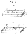
- FIGs. 4(a) and 4(b) are modifications of the container employed in the substance vaporizing apparatus in the first embodiment.
- a container 221 shown in Fig. 4(a) has the shape of a box and is provided with a plurality of through holes 24 differing from each other in diameter. The diameters of the through holes 24 nearer to the opposite ends of the container 221 are greater than those of the through holes 24 nearer to the middle of the container 221.
- a container 221 shown in Fig. 4(b) is provided with a plurality of through holes 24 of the same diameter. The density of the through holes 24 is increased with axial distance from a predetermined axial position in the discharge tube 2.
- These modifications are the same in effect as the container 22 employed in the substance vaporizing apparatus in the second embodiment.
- the first embodiment and its modifications has an effect of increasing the space utilization efficiency, enabling the substance vaporizing apparatus to be formed in a compact construction and enhancing the output of the substance vaporizing apparatus.
- a substance vaporizing apparatus in a second embodiment comprises a gas-filled discharge tube 2 defining a discharge space 3, and a container 222 formed of a porous material, such as a porous ceramic, and provided within the discharge tube 2.
- a vapor generated in the container 222 is emitted from the container 222 through pores into the discharge space 3.
- the metal vapor emitting rate is suppressed by using a porous ceramic material having an appropriate pore density.
- the vapor is emitted in a uniform density distribution into the discharge space 2, so that the laser output is enhanced.
- a laminated porous sheet 223 is formed by laminating a meshed or porous sheet 30, a metal sheet 4 and a substrate 31 in that order, and fastening the sheet 30 and the metal sheet 4 to the substrate 31 with pins 32.
- the laminated porous sheet 223 is wound in a tubular shape with the porous sheet 30 inside so as to surround the discharge space 3.
- the vapor 5 of the metal sheet 4 is emitted through the porous sheet 30 into the discharge space 3.
- the porous sheet 223 has pores formed therein in a small pore density to suppress the vapor emitting rate.
- the substrate 31 may be formed so as to function as a discharge tube 2 as well as the substrate proper.
- the container of the second embodiment has the effect of the second embodiment.
- Fig. 7 shows a substance vaporizing apparatus in a third embodiment according to the present invention.
- the substance vaporizing apparatus comprises a discharge tube 2 defining a discharge space 3, and a plurality of tubular containers 224 and 225 disposed in the periphery of the discharge space 3 and provided with through holes 24.
- Metal vapors 5 generated in the containers 224 and 225 are emitted radially inward through the through holes 24 into the discharge space 3.
- the vapor density in the discharge space is adjusted properly and the vapor is emitted into the discharge space 3 in a uniform vapor density distribution by selectively determining the respective diameters of the through holes 24.
- the containers 224 and 225 may be substituted by the laminated porous sheet employed in the third embodiment.
- the metal vapor is supplied from the periphery of the discharge space 3 so that the metal vapor can uniformly be distributed in the central region of the discharge space 3.
- the vapor emitting rate can be adjusted by selectively determining the respective diameters of the through holes 24, so that the efficiency of utilization can be increased and the substance vaporizing apparatus can be formed in a compact construction.
- Fig. 8 shows a substance vaporizing apparatus in a fourth embodiment according to the present invention.
- This substance vaporizing apparatus comprises a discharge tube 2 defining a discharge space 3, a plurality of containers 224 and 225, and a holding ring 33 for fixedly holding the containers 224 and 225 in the discharge space 3.
- the holding ring 33 is formed of a heat-resistant material, such as a ceramic, molybdenum or tungsten, and is fitted in one end of the discharge tube 2.
- the holding ring 33 is provided with, for example, four holes 33a in which the plurality of containers 224 and 225 are fitted.
- the holding ring 33 fixedly holding the containers 224 and 225 in the end of the discharge tube 2 to disposed the containers 224 and 225 at desired positions within the discharge space 3 so that the efficiency of utilization is increased.
- the substance vaporizing apparatus is able to operate at an improved efficiency.
Landscapes
- Physics & Mathematics (AREA)
- Electromagnetism (AREA)
- Engineering & Computer Science (AREA)
- Plasma & Fusion (AREA)
- Optics & Photonics (AREA)
- Lasers (AREA)
Claims (4)
- Vorrichtung zum Verdampfen von Substanzen zum Erzeugen eines Dampfes einer Substanz für die Verwendung als angeregtes Medium oder ionisiertes Medium in einer Dampfionen-Laservorrichtung, bei der der Dampf (5) durch Erhitzen der Substanz (4) in einer gasgefüllten Röhre (2) erzeugt wird, die einen Entladungsraum (3) bildet und Entladungselektroden (1a, 1b) hat, welche Vorrichtung mindestens einen Behälter (22) umfaßt, der eine Substanz (4) enthält, welcher mindestens eine Behälter (22) in der gasgefüllten Röhre (2) angeordnet und, wenn die genannte Vorrichtung nur einen Behälter (22) enthält, welcher eine Behälter mit einer Mehrzahl von durch seine Wandung hindurchreichenden Öffnungen (24) versehen ist und, wenn die genannte Vorrichtung eine Mehrzahl von Behältern (22) enthält, welche Behälter je mit einer oder einer Mehrzahl von durch ihre Wandung hindurch-reichenden Öffnungen (24) versehen sind, wodurch die genannten Öffnungen als Verbindung des Inneren des mindestens einen Behälters (22) mit dem Inneren der gasgefüllten Röhre (2) dienen und damit einen Durchfluß für den im genannten, mindestens einen Behälter (22) erzeugten Dampf (5) bilden, um vom Inneren des mindestens einen Behälters (22) in das Innere der gasgefüllten Röhre (2) zu fließen, bei dera) der jeweilige Durchmesser der den axial entgegengesetzten Enden der Röhre (2) näherliegenden Öffnungen (24) größer ist als der Durchmesser der Öffnungen (24), die näher zur Mitte der Röhre (2) angeordnet sind, oderb) die Abstände zwischen den den axial entgegengesetzten Enden der Röhre (2) näher liegenden Öffnungen (24) kleiner sind als die Abstände zwischen Öffnungen (24), die näher zur Mitte der Röhre (2) angeordnet sind,wodurch die Gesamtfläche der genannten Öffnungen (24) pro Längeneinheit der genannten Röhre (2) in der Umgebung der axial entgegengesetzten Enden der Röhre (2) größer ist als in der Umgebung der Röhrenmitte und die Dampfabgaberate des Behälters (22) dadurch gegenüber der axialen Richtung der gasgefüllten Röhre (2) variiert, so daß in axialer Richtung der Röhre (2) im Röhreninnern eine im wesentlichen einheitliche Verteilung der Dampfdichte erreicht wird.
- Vorrichtung zum Verdampfen von Substanzen nach Anspruch 1 mit nur einem Behälter (22), bei der der Behälter (22) ein poröses Teil ist, das um die Substanz (4) herum angeordnet ist, so daß die Poren des porösen Teils die genannten Öffnungen darstellen, und welches poröse Teil in der gasgefüllten Röhre (2) angeordnet ist und einen porösen Durchflußfpad für den in dem porösen Teil erzeugten Dampf (5) bildet, um vom Inneren des porösen Teils in das Innere der gasgefüllten Röhre (2) zu fließen.
- Vorrichtung zum Verdampfen von Substanzen nach Anspruch 1 mit einer Mehrzahl von die Substanz (4) enthaltenden Behältern (22), die um den genannten Entladungsraum (3) herum angeordnet sind und von denen jeder Behälter (22) mit einer Mehrzahl von Öffnungen (24) versehen ist, die durch seine Wandung hindurchreichen, um das Innere jedes der Behälter (22) mit dem Entladungsraum (3) zu verbinden und dadurch einen Durchfluß für den in den Behältern (22) erzeugten Dampf (5) zu bilden, damit dieser vom Inneren jedes der Behälter (22) in den Entladungsraum (3) der gasgefüllten Röhre (2) fließen kann.
- Vorrichtung zum Verdampfen von Substanzen nach Anspruch 1 oder 3 mit einem oder einer Mehrzahl von die Substanz (4) enthaltenden und in der gasgefüllten Röhre (2) angeordneten Behältern (224, 225) sowie mit einer Halterung (33), die den Behälter oder die Behälter (224, 225) fest in einer festgelegten Position innerhalb der gasgefüllten Röhre (2) hält.
Priority Applications (1)
| Application Number | Priority Date | Filing Date | Title |
|---|---|---|---|
| EP94111354A EP0622875B1 (de) | 1989-06-14 | 1990-06-12 | Apparat zur Verdampfung von Substanzen |
Applications Claiming Priority (6)
| Application Number | Priority Date | Filing Date | Title |
|---|---|---|---|
| JP15192789A JPH0317260A (ja) | 1989-06-14 | 1989-06-14 | 物質蒸気発生装置 |
| JP151933/89 | 1989-06-14 | ||
| JP15193389A JPH0318076A (ja) | 1989-06-14 | 1989-06-14 | 金属蒸気レーザ装置 |
| JP152675/89 | 1989-06-14 | ||
| JP1152675A JP2760059B2 (ja) | 1989-06-14 | 1989-06-14 | 物質蒸気発生装置 |
| JP151927/89 | 1989-06-14 |
Related Child Applications (2)
| Application Number | Title | Priority Date | Filing Date |
|---|---|---|---|
| EP94111354A Division EP0622875B1 (de) | 1989-06-14 | 1990-06-12 | Apparat zur Verdampfung von Substanzen |
| EP94111354.0 Division-Into | 1994-07-21 |
Publications (3)
| Publication Number | Publication Date |
|---|---|
| EP0402842A2 EP0402842A2 (de) | 1990-12-19 |
| EP0402842A3 EP0402842A3 (de) | 1992-02-26 |
| EP0402842B1 true EP0402842B1 (de) | 1995-09-20 |
Family
ID=27320189
Family Applications (2)
| Application Number | Title | Priority Date | Filing Date |
|---|---|---|---|
| EP94111354A Expired - Lifetime EP0622875B1 (de) | 1989-06-14 | 1990-06-12 | Apparat zur Verdampfung von Substanzen |
| EP90111049A Expired - Lifetime EP0402842B1 (de) | 1989-06-14 | 1990-06-12 | Vorrichtung zum Verdampfen von Substanzen |
Family Applications Before (1)
| Application Number | Title | Priority Date | Filing Date |
|---|---|---|---|
| EP94111354A Expired - Lifetime EP0622875B1 (de) | 1989-06-14 | 1990-06-12 | Apparat zur Verdampfung von Substanzen |
Country Status (3)
| Country | Link |
|---|---|
| US (1) | US5150375A (de) |
| EP (2) | EP0622875B1 (de) |
| DE (2) | DE69031430T2 (de) |
Cited By (1)
| Publication number | Priority date | Publication date | Assignee | Title |
|---|---|---|---|---|
| DE102010055285A1 (de) | 2010-12-21 | 2012-06-21 | Solarion Ag Photovoltaik | Verdampferquelle, Verdampferkammer und Beschichtungsverfahren |
Families Citing this family (9)
| Publication number | Priority date | Publication date | Assignee | Title |
|---|---|---|---|---|
| GB2262184B (en) * | 1991-11-07 | 1995-06-07 | Mitsubishi Electric Corp | Pulse laser apparatus |
| JPH0613196A (ja) * | 1992-06-25 | 1994-01-21 | Matsushita Electric Ind Co Ltd | プラズマ発生方法および発生装置 |
| US5327446A (en) * | 1993-03-26 | 1994-07-05 | The United States Of America As Represented By The Secretary Of The Department Of Health And Human Services | Method of exciting laser action and delivering laser energy for medical and scientific applications |
| US6738400B1 (en) * | 1993-07-07 | 2004-05-18 | The United States Of America As Represented By The United States Department Of Energy | Large diameter lasing tube cooling arrangement |
| DE4422697C1 (de) * | 1994-06-29 | 1996-01-25 | Zsw | Verdampferquelle für eine Aufdampfanlage und ihre Verwendung |
| FR2743204B1 (fr) * | 1996-01-03 | 1998-02-13 | Commissariat Energie Atomique | Dispositif laser a vapeur metallique |
| FR2836772B1 (fr) * | 2002-03-04 | 2004-07-09 | Absys | Generateur de gaz pour un systeme de sterilisation |
| US20030168013A1 (en) * | 2002-03-08 | 2003-09-11 | Eastman Kodak Company | Elongated thermal physical vapor deposition source with plural apertures for making an organic light-emitting device |
| RU2618477C1 (ru) * | 2015-12-24 | 2017-05-03 | Федеральное государственное автономное образовательное учреждение высшего образования "Национальный исследовательский Томский государственный университет" (ТГУ, НИ ТГУ) | Импульсно-периодический лазер на парах химических элементов |
Family Cites Families (12)
| Publication number | Priority date | Publication date | Assignee | Title |
|---|---|---|---|---|
| FR2092912B1 (de) * | 1970-06-30 | 1973-12-21 | Comp Generale Electricite | |
| US4021845A (en) * | 1975-10-16 | 1977-05-03 | Xerox Corporation | Laser for generating white light |
| US4052680A (en) * | 1976-07-01 | 1977-10-04 | Xerox Corporation | Metal vapor laser having cataphoresis means |
| DE2824761A1 (de) * | 1977-06-08 | 1978-12-14 | Gen Electric | Entladungserhitzter kupferdampf-laser |
| US4639926A (en) * | 1980-06-09 | 1987-01-27 | Xerox Corporation | Efficient cathode assembly for metal vapor laser |
| JPS5835992A (ja) * | 1981-08-28 | 1983-03-02 | Mita Ind Co Ltd | 負グロ−を利用するレ−ザ管 |
| JPS61244081A (ja) * | 1985-04-23 | 1986-10-30 | Koito Mfg Co Ltd | 金属イオンレ−ザ− |
| JPH06101605B2 (ja) * | 1985-07-22 | 1994-12-12 | 株式会社小糸製作所 | 金属イオンレ−ザ− |
| US4677636A (en) * | 1985-10-23 | 1987-06-30 | The United States Of America As Represented By The Administrator Of The National Aeronautics And Space Administration | Multiplex electric discharge gas laser system |
| GB8711212D0 (en) * | 1987-05-12 | 1987-06-17 | English Electric Valve Co Ltd | Laser apparatus |
| JPS63281484A (ja) * | 1987-05-13 | 1988-11-17 | Ushio Inc | ホロ−カソ−ド型金属蒸気レ−ザ管 |
| US4975924A (en) * | 1987-08-13 | 1990-12-04 | Mitsubishi Denki Kabushiki Kaisha | Metallic vapor laser apparatus |
-
1990
- 1990-06-11 US US07/535,615 patent/US5150375A/en not_active Expired - Fee Related
- 1990-06-12 EP EP94111354A patent/EP0622875B1/de not_active Expired - Lifetime
- 1990-06-12 EP EP90111049A patent/EP0402842B1/de not_active Expired - Lifetime
- 1990-06-12 DE DE69031430T patent/DE69031430T2/de not_active Expired - Fee Related
- 1990-06-12 DE DE69022487T patent/DE69022487T2/de not_active Expired - Fee Related
Cited By (2)
| Publication number | Priority date | Publication date | Assignee | Title |
|---|---|---|---|---|
| DE102010055285A1 (de) | 2010-12-21 | 2012-06-21 | Solarion Ag Photovoltaik | Verdampferquelle, Verdampferkammer und Beschichtungsverfahren |
| WO2012084165A1 (de) | 2010-12-21 | 2012-06-28 | Solarion Ag - Photovoltaik | Verdampferquelle, verdampferkammer, beschichtungsverfahren und düsenplatte |
Also Published As
| Publication number | Publication date |
|---|---|
| DE69031430D1 (de) | 1997-10-16 |
| EP0402842A2 (de) | 1990-12-19 |
| US5150375A (en) | 1992-09-22 |
| DE69022487T2 (de) | 1996-02-08 |
| EP0622875A1 (de) | 1994-11-02 |
| EP0402842A3 (de) | 1992-02-26 |
| EP0622875B1 (de) | 1997-09-10 |
| DE69022487D1 (de) | 1995-10-26 |
| DE69031430T2 (de) | 1998-01-22 |
Similar Documents
| Publication | Publication Date | Title |
|---|---|---|
| US2755014A (en) | Ionic vacuum pump device | |
| US4942588A (en) | Laser device | |
| KR100586050B1 (ko) | 하전입자빔과 관련한 개선된 장치 | |
| JPH0337277B2 (de) | ||
| GB2079523A (en) | Metal vapour laser | |
| JP3738181B2 (ja) | プラズマ・インジェクター | |
| EP0095311B1 (de) | Ionenquelle | |
| US5150375A (en) | Substance vaporizing apparatus | |
| JP2595188B2 (ja) | コンパクトな高電流交差電界プラズマスイッチ | |
| EP0204060B1 (de) | Kompakte Niederdruckquecksilberdampfentladungslampe | |
| US4991180A (en) | Metallic vapor laser apparatus | |
| JPS6355987A (ja) | レ−ザ装置 | |
| US4825446A (en) | Laser apparatus having cathode bore directing electron beam onto anode | |
| US4041415A (en) | Coaxial electron beam pumped laser | |
| JP2760059B2 (ja) | 物質蒸気発生装置 | |
| US3250947A (en) | Discharge device having electron grids with heights rising substantially above the grid support rims | |
| US3750047A (en) | Gas laser having excitation chambers with multiple channels | |
| US3338506A (en) | Vacuum pump apparatus | |
| JPS63199470A (ja) | 金属蒸気レ−ザ発振管 | |
| JPH0635487Y2 (ja) | 金属蒸気レーザ放電管 | |
| JPH07307505A (ja) | ガスレ−ザ装置 | |
| JPH0317256A (ja) | 物質蒸気発生装置 | |
| JP4436003B2 (ja) | 真空成膜装置 | |
| JPH0554812A (ja) | イオン源 | |
| JPS6139593A (ja) | 金属蒸気レ−ザ |
Legal Events
| Date | Code | Title | Description |
|---|---|---|---|
| PUAI | Public reference made under article 153(3) epc to a published international application that has entered the european phase |
Free format text: ORIGINAL CODE: 0009012 |
|
| AK | Designated contracting states |
Kind code of ref document: A2 Designated state(s): DE FR GB |
|
| PUAL | Search report despatched |
Free format text: ORIGINAL CODE: 0009013 |
|
| AK | Designated contracting states |
Kind code of ref document: A3 Designated state(s): DE FR GB |
|
| RHK1 | Main classification (correction) |
Ipc: H01S 3/227 |
|
| 17P | Request for examination filed |
Effective date: 19920819 |
|
| 17Q | First examination report despatched |
Effective date: 19931025 |
|
| GRAA | (expected) grant |
Free format text: ORIGINAL CODE: 0009210 |
|
| AK | Designated contracting states |
Kind code of ref document: B1 Designated state(s): DE FR GB |
|
| XX | Miscellaneous (additional remarks) |
Free format text: TEILANMELDUNG 94111354.0 EINGEREICHT AM 12/06/90. |
|
| REF | Corresponds to: |
Ref document number: 69022487 Country of ref document: DE Date of ref document: 19951026 |
|
| ET | Fr: translation filed | ||
| PLBE | No opposition filed within time limit |
Free format text: ORIGINAL CODE: 0009261 |
|
| STAA | Information on the status of an ep patent application or granted ep patent |
Free format text: STATUS: NO OPPOSITION FILED WITHIN TIME LIMIT |
|
| 26N | No opposition filed | ||
| PGFP | Annual fee paid to national office [announced via postgrant information from national office to epo] |
Ref country code: GB Payment date: 20000607 Year of fee payment: 11 |
|
| PGFP | Annual fee paid to national office [announced via postgrant information from national office to epo] |
Ref country code: FR Payment date: 20000612 Year of fee payment: 11 |
|
| PGFP | Annual fee paid to national office [announced via postgrant information from national office to epo] |
Ref country code: DE Payment date: 20000614 Year of fee payment: 11 |
|
| REG | Reference to a national code |
Ref country code: FR Ref legal event code: D6 |
|
| PG25 | Lapsed in a contracting state [announced via postgrant information from national office to epo] |
Ref country code: GB Free format text: LAPSE BECAUSE OF NON-PAYMENT OF DUE FEES Effective date: 20010612 |
|
| GBPC | Gb: european patent ceased through non-payment of renewal fee |
Effective date: 20010612 |
|
| PG25 | Lapsed in a contracting state [announced via postgrant information from national office to epo] |
Ref country code: FR Free format text: LAPSE BECAUSE OF NON-PAYMENT OF DUE FEES Effective date: 20020228 |
|
| PG25 | Lapsed in a contracting state [announced via postgrant information from national office to epo] |
Ref country code: DE Free format text: LAPSE BECAUSE OF NON-PAYMENT OF DUE FEES Effective date: 20020403 |