EP0402839B1 - Anschnallvorrichtung - Google Patents
Anschnallvorrichtung Download PDFInfo
- Publication number
- EP0402839B1 EP0402839B1 EP90111031A EP90111031A EP0402839B1 EP 0402839 B1 EP0402839 B1 EP 0402839B1 EP 90111031 A EP90111031 A EP 90111031A EP 90111031 A EP90111031 A EP 90111031A EP 0402839 B1 EP0402839 B1 EP 0402839B1
- Authority
- EP
- European Patent Office
- Prior art keywords
- tongue plate
- lock member
- buckle body
- plate
- buckle
- Prior art date
- Legal status (The legal status is an assumption and is not a legal conclusion. Google has not performed a legal analysis and makes no representation as to the accuracy of the status listed.)
- Expired - Lifetime
Links
- 238000003780 insertion Methods 0.000 claims description 21
- 230000037431 insertion Effects 0.000 claims description 21
- 230000000694 effects Effects 0.000 claims description 2
- 230000002093 peripheral effect Effects 0.000 claims 2
- 230000006835 compression Effects 0.000 description 15
- 238000007906 compression Methods 0.000 description 15
- 230000000630 rising effect Effects 0.000 description 12
- 230000001133 acceleration Effects 0.000 description 8
- 230000000717 retained effect Effects 0.000 description 8
- 210000000078 claw Anatomy 0.000 description 3
- 239000000463 material Substances 0.000 description 2
- 230000001012 protector Effects 0.000 description 2
- 238000009877 rendering Methods 0.000 description 2
- 238000005452 bending Methods 0.000 description 1
- 230000003292 diminished effect Effects 0.000 description 1
- 210000005182 tip of the tongue Anatomy 0.000 description 1
Images


Classifications
-
- A—HUMAN NECESSITIES
- A44—HABERDASHERY; JEWELLERY
- A44B—BUTTONS, PINS, BUCKLES, SLIDE FASTENERS, OR THE LIKE
- A44B11/00—Buckles; Similar fasteners for interconnecting straps or the like, e.g. for safety belts
- A44B11/25—Buckles; Similar fasteners for interconnecting straps or the like, e.g. for safety belts with two or more separable parts
- A44B11/2503—Safety buckles
- A44B11/2507—Safety buckles actuated by a push-button
- A44B11/2523—Safety buckles actuated by a push-button acting parallel to the main plane of the buckle and in the same direction as the fastening action
-
- Y—GENERAL TAGGING OF NEW TECHNOLOGICAL DEVELOPMENTS; GENERAL TAGGING OF CROSS-SECTIONAL TECHNOLOGIES SPANNING OVER SEVERAL SECTIONS OF THE IPC; TECHNICAL SUBJECTS COVERED BY FORMER USPC CROSS-REFERENCE ART COLLECTIONS [XRACs] AND DIGESTS
- Y10—TECHNICAL SUBJECTS COVERED BY FORMER USPC
- Y10T—TECHNICAL SUBJECTS COVERED BY FORMER US CLASSIFICATION
- Y10T24/00—Buckles, buttons, clasps, etc.
- Y10T24/45—Separable-fastener or required component thereof [e.g., projection and cavity to complete interlock]
- Y10T24/45225—Separable-fastener or required component thereof [e.g., projection and cavity to complete interlock] including member having distinct formations and mating member selectively interlocking therewith
- Y10T24/45602—Receiving member includes either movable connection between interlocking components or variable configuration cavity
- Y10T24/45623—Receiving member includes either movable connection between interlocking components or variable configuration cavity and operator therefor
- Y10T24/45639—Receiving member includes either movable connection between interlocking components or variable configuration cavity and operator therefor including pivotally connected element on receiving member
- Y10T24/45644—Receiving member includes either movable connection between interlocking components or variable configuration cavity and operator therefor including pivotally connected element on receiving member for shifting pivotally connected interlocking component
-
- Y—GENERAL TAGGING OF NEW TECHNOLOGICAL DEVELOPMENTS; GENERAL TAGGING OF CROSS-SECTIONAL TECHNOLOGIES SPANNING OVER SEVERAL SECTIONS OF THE IPC; TECHNICAL SUBJECTS COVERED BY FORMER USPC CROSS-REFERENCE ART COLLECTIONS [XRACs] AND DIGESTS
- Y10—TECHNICAL SUBJECTS COVERED BY FORMER USPC
- Y10T—TECHNICAL SUBJECTS COVERED BY FORMER US CLASSIFICATION
- Y10T24/00—Buckles, buttons, clasps, etc.
- Y10T24/45—Separable-fastener or required component thereof [e.g., projection and cavity to complete interlock]
- Y10T24/45225—Separable-fastener or required component thereof [e.g., projection and cavity to complete interlock] including member having distinct formations and mating member selectively interlocking therewith
- Y10T24/45602—Receiving member includes either movable connection between interlocking components or variable configuration cavity
- Y10T24/45623—Receiving member includes either movable connection between interlocking components or variable configuration cavity and operator therefor
- Y10T24/4566—Receiving member includes either movable connection between interlocking components or variable configuration cavity and operator therefor including slidably connected and guided element on receiving member
- Y10T24/45665—Receiving member includes either movable connection between interlocking components or variable configuration cavity and operator therefor including slidably connected and guided element on receiving member for shifting pivotally connected interlocking component
Definitions
- the present invention relates to a buckle device for use in a vehicle seat belt system according to the preamble of claim 1.
- a buckle device having a so-called direct locking mechanism in which a lock member is held in a locked state by a release button disposed slidably in the direction of insertion and withdrawal of the tongue plate.
- the locked state of the tongue plate is released by operating the release button by pressing the same.
- the support member undergoes plastic deformation due to a large load acting on the support member, with the result that the overall buckle device moves suddenly in the direction in which the tongue plate is pulled, and the release button moves in the direction in which it is operated for release, by the inertia of the release button.
- the support member is constituted by material such as a webbing and is secured by being wound around an anchor provided on the chassis, and a portion of the webbing adjacent to the wound portion has been sewn in a folded state
- the sewn portion is adapted to be cut off so as to absorb the energy when a large load occurs.
- the release button moves in the direction in which it is operated for release, owing to the inertial force.
- EP-A-212 507 discloses a buckle device with an emergency lock means according to the preamble of the main claim. This buckle device shows an element acting due to an inertial force and preventing the release of the tongue plate inopportunely.
- EP-A-384 703 and EP-A-368 277 also disclose buckle devices with emergency lock means. These applications are comprised in the state of the art according to Article 54(3) and (4)EPC.
- an object of the present invention is to provide a buckle device which makes it possible to maintain the locked state of a tongue plate even when an inertial force acts in a lock releasing direction of a lock releasing means, thereby overcoming the above-described drawbacks of the conventional art.
- the buckle device shows the features of the characterizing part of claim 1.
- the buckle device includes releasing force transmitting means allowing the lock member and the releasing means to interlock with each other.
- the buckle device includes a lock assisting means disposed movably between a locking position for holding the lock member in a state in which it is engaged with the tongue plate and a releasing position in which the lock member can be disengaged from the tongue plate.
- the additional locking device in the event that an inertial force has acted in a predetermined direction in a state in which the lock member is holding the tongue plate in the locked state, holds the lock member in a state of engagement with the tongue plate by preventing the lock member from moving from the locking position to its unlocked position. Accordingly, it is possible to maintain the locked state of the tongue plate even when an inertial force has acted on the releasing means in a predetermined direction.
- the additional locking device is adapted to maintain the locked state of the tongue plate when an inertial force has acted in a predetermined direction, so that the additional locking device may be disposed in any part of the buckle device.
- the locking state of the lock member is released via the releasing force transmitting means, so that the tongue plate can be removed.
- the locking state of the lock member is released as the lock assisting means moves to the releasing position, so that the tongue plate can be removed.
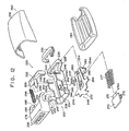
- a buckle device 110 has a buckle body 118 interposed between an upper cover 114 and a lower cover 116.
- this buckle body 118 as shown in Fig. 3, a pair of leg plate portions 124 are formed integrally on transversely opposite sides of a flat plate portion 122 by bending. The arrangement is such that a tongue plate 112 is inserted between the pair of leg plate portions 124 through an opening 125 formed between the upper cover 114 and the lower cover 116.
- an ejector 126 and a lock plate 128 which is a lock member are provided between the pair of leg plate portions 124 of the buckle body 118.
- the ejector 126 is inserted and disposed in a guide hole 130 formed in the flat plate portion 122 of the buckle body 118, and is movable in the direction of insertion and withdrawal of the tongue plate (in the direction of arrow A or B in Figs. 1 and 2).
- One end of a coil spring 132 (shown in Fig. 3) is fitted to a right-hand end, as viewed in the ejector 126, in the direction where the tongue plate 112 is inserted, while the other end is retained by the buckle body 118.
- the ejector 126 is thus urged in the direction of withdrawal of the tongue plate 112 (in the direction of arrow B in Figs. 1 and 2) by the force of this coil spring 132.
- the distal end of the tongue plate 112 is brought into contact with the ejector 126.
- the tongue plate 112 is inserted as shown in Fig. 2, while moving the ejector 126 in the tongue plate inserting direction (in the direction of arrow A in Fig. 1) from the state of withdrawal of the tongue plate shown in Fig. 1.
- the lock plate 128 is elongated in the direction of insertion and withdrawal of the tongue plate (in the direction of arrow A or B in Figs. 1 and 2).
- a U-shaped portion 134 whose end is bent substantially perpendicularly downward is formed at a left end, as viewed in Figs. 1 and 2, of the lock plate 128.
- a distal end portion of this U-shaped portion 134 is formed as an engaging portion 138 for engaging with an engaging hole 136 of the tongue plate 112.
- This engaging portion 138 is fitted in the engaging hole 136 of the tongue plate 112, as shown in Fig. 2, thereby engaging the lock plate 128 with the tongue plate 112.
- An upwardly rising portion 140 is formed at the other end (the right side in Figs. 1 and 2) of the lock plate 128 located away from its U-shaped portion 134.
- the rising portion 140 is elongated in the transverse direction of the lock plate, and the lock plate 128 is trained between the pair of leg plate portions 124 of the buckle body 118 with its transversely opposite ends of the rising portion 140 supported by the leg plate portions 124.
- a substantially triangular notch 142 is formed in a right end, as viewed in Figs. 1 and 2, of each of the leg plate portions 124. Transversely opposite ends of the rising portion 140 are inserted into the notches 142, thereby rendering the lock plate 128 swingable in the direction of disengagement from the tongue plate (in the direction of arrow C or D in Figs. 1 and 2) with each bottom 142A as a center.
- each of the notches 142 is wider than the thickness of the rising portion 140 of the lock plate 128, so that the lock plate 128 is adapted to move by a small amount in the direction of arrow A or B in Fig. 1.
- the lock plate 128 With the tongue plate withdrawn, the lock plate 128 is set in a state in which it is swung in the direction of disengagement from the tongue plate (in the direction of arrow C in Fig. 1) as the end of the engaging portion 138 is brought into contact with an upper surface of the ejector 126, as shown in Fig. 1.
- the lock plate 128 has a pair of downwardly bent portions 144 formed on transversely opposite sides thereof at a longitudinally intermediate position between the U-shaped portion 134 and the rising portion 140.
- the bent portions 144 in the tongue plate-withdrawn state shown in Fig. 1, are pressed in the tongue plate inserting direction (in the direction of arrow A in Fig. 1), the lock plate 128 is swung in the direction of engagement with the tongue plate (in the direction of arrow D in Fig. 1).
- These bent portions 144 correspond to right ends, as viewed in Figs. 1 and 2, of a block 146 which is integrally provided on an upper surface of the ejector 126.
- the arrangement is such that when the tongue plate 112 in the tongue plate-withdrawn state shown in Fig. 1 is inserted, the ejector 126 presses the bent portions 144 in the tongue plate inserting direction (in the direction of arrow A in Fig. 1), and is moved in the tongue plate inserting direction, as shown in Fig. 2, while swinging the lock plate 128 in the direction of engagement with the tongue plate (in the direction of arrow D in Fig. 1).
- the lock plate 128 is engaged with the tongue plate 112 as the tip of the engaging portion 138 is inserted in the engaging hole 136 of the tongue plate 112, as shown in Fig. 2, due to its swinging motion at that time.
- a spring holder 148 retained by the rising portion 140 is fixed to the lock plate 128.
- One ends of two coil springs 150, 152 (shown in Fig. 3) are retained by the spring holder 148.
- the other ends of these two coil springs 150, 152 are respectively disposed more towards the tongue plate 112, as viewed in Figs. 1 and 2, than the spring holder 148, and are retained by a release button 154 which is a releasing means and a lock pin holder 156.
- the release button 154 and the lock pin holder 156 are respectively urged in the tongue plate withdrawing direction (in the direction of arrow B in Figs. 1 and 2) by means of the coil springs 150, 152.
- the release button 154 is disposed more towards the tongue plate 112, as viewed in Figs. 1 and 2, than the lock pin holder 156, and are movable in the direction of insertion and withdrawal of the tongue plate (in the direction of arrow A or B in Figs. 1 and 2).
- the release button 154 is movable in the tongue plate inserting direction (in the direction of arrow A in Figs. 1 and 2) against the urging force of the coil spring 150 (shown in Fig. 3).
- a pair of blocks 158 are provided at a right-hand end, as viewed in Figs. 1 and 2, of the release button 154 in such a manner as to project in the tongue plate inserting direction (in the direction of arrow A in Figs. 1 and 2).
- the blocks 158 are inserted into rectangular holes 160 (shown in Fig. 3) provided in an upper end portion of the lock pin holder 156 in such a manner as to be axially movable, and correspond to an upper end of the rising portion 140 of the lock plate 128. These blocks 158 are arranged such that when the release button 154 in the state of engagement with the tongue plate is moved in the tongue plate inserting direction (in the direction of arrow A in Fig. 2) against the urging force of the coil spring 150 (shown in Fig.
- the blocks 158 are brought into contact with the upper end of the rising portion 140 of the lock plate 128 midway during their movement, and press the rising portion 140 of the lock plate 128, thereby moving the lock plate 128 in the tongue plate inserting direction while swinging the same in the direction of disengagement with the tongue plate (in the direction of arrow C in Fig. 2). Due to this swinging, the lock plate 128 is adapted to cause the engaging portion 138 to be withdrawn from the engaging hole 136 of the tongue plate 112 from the state of its engagement with the tongue plate shown in Fig. 2.
- the lock pin holder 156 which is urged by the coil spring 152 (shown in Fig. 3), is adapted to clamp a lock pin 162 (serving as a lock assisting means) between the same and the release button 154, as shown in Fig. 2, on the outer sides of the leg plate portions 124 of the buckle body 118 in the state of engagement of the tongue plate.
- the lock pin 162 is supported by the buckle body 118 with its axially opposite ends inserted in bearing holes 164 respectively provided in the leg plate portions 124 of the buckle body 118.
- the bearing holes 164 are elongated in the direction of insertion and withdrawal of the tongue plate (in the direction of arrow A or B in Figs. 1 and 2) so as to support the lock pin 162 movably in the direction of insertion and release of the tongue plate.
- the lock pin 162 corresponds to a pair of positioning plate portions 166 provided in the lock plate 128. As shown in Fig. 3, the positioning plate portions 166 extend in the transverse direction of the lock plate from its intermediate portion substantially orthogonal to the engaging portion 138 of the U-shaped portion 134. In the state of engagement of the tongue plate, the lock pin 162 abuts against the upper surfaces of the positioning plate portions 166, as shown in Fig. 2. In the state in which the tongue plate is withdrawn, the lock pin 162 abuts against the right end faces, as viewed in Figs. 1 and 2, of the positioning plate portions 166, as shown in Fig. 2.
- the lock pin in the state of engagement of the tongue plate is clamped by the lock pin holder 156 and the release button 154 and corresponds to the upper surfaces of the positioning plate portions 166.
- the lock plate 128 is prevented from swinging in the direction of disengagement from the tongue plate (in the direction of arrow C in Fig. 2) by means of the lock pin 162.
- the lock pin 162 in this tongue plate engaging state is moved in the tongue plate inserting direction (in the direction of arrow A in Fig. 2) and is hence positioned more towards the tongue plate inserting direction as viewed in Figs.
- the lock plate 128 becomes swingable in the direction of disengagement from the tongue plate (in the direction of arrow C in Fig. 2).
- a protrusion 168 serving as an engagement assisting means is provided projectingly on a bottom 116A of the lower cover 116.
- a distal end portion of this protrusion 168 is bent orthogonally in the direction of withdrawal of the tongue plate 112 (in the direction of arrow B) so as to constitute a retaining claw 168A which is an additional locking device.
- a retaining hole 170 is provided in a distal end portion of the engaging portion 138 of the lock plate 128.
- the retaining claw 168A of the protrusion 168 of the lower cover 116 fits into and engages with the retaining hole 170.
- Fig. 1 illustrates a state in which the tongue plate 112 is not engaged with the buckle device 110. If the tongue plate 112 is inserted in the buckle device 110 in this state, the tip of the tongue plate 112 is brought into contact with the ejector 126 and presses the ejector 126 in the tongue plate inserting direction (in the direction of arrow A in Fig. 1) against the urging force of the coil spring 132. The tongue plate 112 is thus moved in the tongue plate inserting direction while the ejector 126 is being moved in the tongue plate inserting direction (in the direction of arrow A in Fig. 1).
- the ejector 126 During its movement, the ejector 126 is brought into contact with the bent portions 144 of the lock plate 128 and press the bent portions 144 of the lock plate 128 in the tongue plate inserting direction (in the direction of arrow A in Fig. 1). The ejector 126 is moved in the tongue plate inserting direction (in the direction of arrow A in Fig. 1) while swinging the lock plate 128 in the tongue plate engaging direction (in the direction of arrow D in Fig. 1). While the tongue plate 112 is being moved in the tongue plate inserting direction, the engaging portion 138 of the lock plate 128 is inserted into the engaging hole 136.
- the lock pin 162 is movable in the tongue plate withdrawing direction (in the direction of arrow B in Fig. 1) by the swinging of the lock plate 128.
- the lock pin 162 moves in the tongue plate withdrawing direction through the urging of the coil spring 152 via the lock pin holder 156.
- the lock pin is clamped by the lock pin holder 156 and the release button 154, and corresponds to the upper surfaces of the positioning plate portions 166 (locked position).
- This state is the tongue plate engaged position shown in Fig. 2.
- the lock plate 128 is prevented from swinging in the tongue plate disengaging direction (in the direction of arrow C in Fig. 2) by means of the lock pin 162, and the engaging portion 138 of the lock plate 128 is prevented from coming out of the engaging hole 136 of the tongue plate 112, so that the tongue plate 112 is not inadvertently removed from the buckle device 110.
- the arrangement provided is such that the lock plate 128 is impossible to move in the direction of arrow B, C, or D, nor can it move in the axial direction thereof. Accordingly, with the buckle device of this embodiment, no matter from which direction the inertial force comes, the lock plate 128 is held in the tongue plate engaging state.
- the release button 154 When the tongue plate 112 is to be released from the buckle device 110, the release button 154 is moved by the occupant in the tongue plate inserting direction (in the direction of arrow A in Fig. 2) against the urging force of the coil spring 150. With the lock pin 162 clamped by the release button 154 and the lock pin holder 156, the release button 154 is moved in the tongue plate inserting direction while moving the lock pin 162 and the lock pin holder 156 in the tongue plate inserting direction (in the direction of arrow A in Fig. 2) against the urging force of the coil spring 152 (shown in Fig. 3).
- the block 158 of the release button 154 is brought into contact with the upper end portion of the rising portion 140 of the lock plate 128.
- the release button 154 presses the rising portion 140 of the lock plate 128 in the tongue plate inserting direction, and is further moved in the tongue plate inserting direction while swinging the lock plate 128 in the tongue plate releasing direction (in the direction of arrow C in Fig. 2).
- the engaging portion 138 of the lock plate 128 disengages from the engaging hole 136 of the tongue plate 112 owing to the swinging motion at that time.
- the ejector 126 is urged by the coil spring 132 and moved in the tongue plate withdrawing direction (in the direction of arrow B in Fig. 2), and the tongue plate 112 springs out of the buckle device 110 by being pressed by the ejector 126, thereby returning to the state shown in Fig. 2.
- a pair of retaining projections 172 serving as one part of an emergency lock means are formed between the U-shaped portion 134 and the bent portions 144 of the lock plate 128, respectively.
- a pair of retaining projections 174 serving as another part of the emergency lock means are respectively formed on the inner sides of the leg plate portions 124 of the buckle device 118 corresponding to the retaining projections 172 at positions located on the right side, as viewed in Fig. 4, of the leg plate portions 124.
- the arrangement is such that when the lock plate 128 moves in the direction of arrow A by an inertial force or the like, the retaining projections 172 of the lock plate 128 move and are caught at the left sides, as viewed in Fig. 4, of the retaining projections 174 of the buckle body 118, thereby holding the lock plate 128 in the tongue plate engaging state.
- a buckle device 220 main component parts of a buckle device 220 are accommodated in a buckle body 222.
- the buckle body 222 is formed by processing a plate material having a predetermined strength.
- a connecting portion 226 is formed at one end thereof.
- An opening 228 is formed in the connecting portion 226, and one end of a strap 232 (see Figs. 6 and 7) is connected to this opening 228 via a protector 230.
- the other end of the strap 232 is secured to the chassis via an anchor plate or the like.
- an opening 236 is formed in a base plate portion 234 serving as a base bottom for connection with the connecting portion 226.
- a pair of substantially rectangular notches 242 are formed in upper intermediate portions of a pair of leg plate portions 240 provided uprightly from transversely opposite sides of the base plate portion 234 and are in parallel with each other.
- a pair of guide flanges 244 projecting outwardly from the leg plate portions 240 are formed on front sides, i.e., left sides as viewed in Fig. 6, of the leg plate portions 240 adjacent to the aforementioned notches 242.
- a pair of projections 245 for positioning a tongue plate 296 see Fig.
- notches 246 are formed on front sides, i.e., right sides as viewed in Fig. 6, of the leg plate portions 240.
- a hook 252 bent downwardly at a central portion of a front end of a central flat plate portion 250 as well as a hinge 254 bent downwardly at a rear end of the central flat plate portion 250.
- a pair of projections 256 are formed at a forward position of the central flat plate portion 250 in such a manner as to project outwardly from transversely opposite sides of the central flat plate portion 250.
- a slot 250A extending longitudinally and reaching the hinge 254 is formed in a central portion of the central flat plate portion 250. This slot 250A is formed into a tapered configuration having a diminished width at the hinge 254 side.
- a pair of notches 260 are formed on opposite sides of an intermediate portion of the hinge 254.
- the side surface of the hook 252 is formed into an arcuate configuration with the notches 260 as the center, as shown in Fig. 6.
- a projection 238 is formed at a distal end of the hinge 254 in such a manner as to project toward the hook 252.
- the hinge 254 is inserted into the opening 228 formed in the connecting portion 226, and the notches 260 formed in the hinge 254 are retained by the connecting portion 226, thereby rendering the lock plate 248 swingable with respect to the buckle body 222.
- the aforementioned protector 230 is fitted in the opening 228 after the lock plate 248 is inserted, as described above, and also functions as a stopper for preventing the lock plate 248 from coming out.
- a rear surface of the lock plate 248 on the front side thereof, including the projections 256 is capable of abutting against bottom surfaces 242A of the notches 242, 242 formed in the buckle body leg plate portions 240. With the lock plate 248 abutting against the bottom surfaces 242A, the end of the hook 252 is situated in the opening 236 formed in the buckle body base plate portion 234.
- a compression coil spring 276 having the other end supported by an ejector 270 is retained to the projection 238 of the lock plate 248.
- the lock plate 248 is urged by the compression coil spring 276 and counterclockwise torque, as viewed in Fig. 6, (in the direction of arrow D) is imparted to the lock plate 248 with the notches 260 formed in the hinge 254 serving as a fulcrum.
- a pair of projections 257 serving as a part of an emergency lock means is formed rearwardly of the projections 256 of the central flat plate portion 250 in parallel with the projections 256. Front end portions of these projections 257 are bent downwardly, and are then further bent forwardly, thereby forming L-shaped hooks 257A.
- An upper portion of the ejector 270 is formed into a flat rectangular shape having a width greater than the width of the opening 236 formed in the flat plate portion of the buckle body 222.
- a guide portion 272 fitting slidably into the opening 236 is formed in a lower rear portion of the ejector 270.
- a spring support 274 is formed projectingly at the rear of the ejector 270.
- a compression coil spring 276 is disposed between the spring support 274 and the projection 238 of the hinge 254 of the lock plate 248 so as to urge the ejector 270 leftwards as viewed in Fig. 6 (in the direction of arrow B in Fig. 6).
- a pair of hooks 273 serving as another part of the emergency lock means are formed at transversely opposite ends of the ejector 270 in such a manner as to project upward. Distal ends 273A of the hooks 273 are bent rearwardly, and when the ejector 270 moves rightward as viewed in Fig. 6 (in the direction of arrow A in Fig. 6), the distal ends 273A engage the hooks 257A of the lock plate 248 (the state shown in Fig. 9).
- a holder 262 is retained by the buckle body 222 with its notches 266 fitted to the notches 246 formed in the buckle body leg plate portions 240.
- a release button 278 has a pair of wedge-shaped inclined guide portions 282 (only one is shown in the drawing) formed at the inner side of an operating portion 280. These inclined guide portions 282 are brought into contact with a rear surface of the lock plate 248.
- the release button 278 is movable in the direction of arrow A in Fig. 6 by being guided by the guide flanges 244 with rail grooves (not illustrated) fitted to the guide flanges 244 formed in the buckle body leg plate portions 240.
- a spring support 285 is formed on the release button 278, and a compression coil spring 288 is interposed between the support 285 and a spring support 286 formed on the holder 262.
- the release button 278 is urged in the direction of arrow B in Fig. 6.
- a pair of holding arms 289 (serving as lock assisting means) with their ends bent into the configuration of hooks are formed on opposite sides of the release button 278, and these holding arms 289 are positioned in such a manner as to clamp the buckle body leg plate portions 240 from opposite sides thereof.
- a buckle cover 290 is composed of an upper cover 292 and a lower cover 294, and is secured to the buckle body 222, covering the base plate portion 234 and leg plate portions 240.
- the tongue plate 296 has a rectangular opening 298 formed on end tip side, and the horizontal length, as viewed in Fig. 6, of this opening 298 is set to be longer than the thickness of the hook 252, so that the tongue plate 296 is movable in the direction of arrow A or B in Fig. 6.
- one end of an unillustrated webbing is attached to the rear end side (left side in Fig. 6) of the tongue plate 296. The other end of the webbing is secured to the chassis via an anchor plate or the like.
- Fig. 7 illustrates a state before the tongue plate 296 is engaged with the buckle device 220.
- the ejector 270 is situated at its forward limit by being urged by the compression coil spring 276. Its guide portion 272 abuts against an end face of the opening 236 formed in the buckle body base plate portion 234.
- the hook 252 of the lock plate 248 abuts against the upper surface of the ejector 270.
- the lock plate 248 is urged by the compression coil spring 276 and the counterclockwise torque in Fig. 17 (in the direction of arrow D in Fig. 7) is hence imparted to the lock plate 248, so that the hook 252 presses the upper surface of the ejector 270.
- release button 278 is urged in the direction of arrow B in Fig. 1 by means of the compression coil spring 288, the tips of the holding arms 289 are retained by the projections 256 of the lock plate 248, so that the release button 278 has not reached its forward limit.
- the distal end of the hook 252 of the lock plate 248 is situated above the opening 298 of the tongue plate 296, so that the distal end of the hook 252 is instantly rotated and enters the opening 298 since the lock plate 248 is urged in the direction of arrow D in Fig. 7.
- the lock plate 248 rotates, and the distal end of the hook 252 passes through the opening 298 of the tongue plate 296 and is situated in the opening 236 formed in the buckle base plate portion 234.
- the lock plate 248 stops rotating as the front-side rear surface thereof, including the projections 256, is brought into contact with the bottom surfaces 242A formed in the buckle body leg plate portions 240.
- the release button 278 is urged by the compression coil spring 288 and reaches its leftward forward limit since the holding arms 289 are disengaged from the projections 256 of the lock plate 248.
- the inclined guide portions 282 of the release button 278 are pressed against the lock plate 248.
- the distal ends of the holding arms 289 move from the upper surfaces of the projections 256 of the lock plate 248 due to the movement of the release button 278, and the lock plate 248 concurrently moves upwardly along the inclined guide portions 282.
- the lock plate 248 swings in the direction of arrow C in Fig. 6 by using as an axis the portion of the hinge 254 contacting the buckle body 222.
- the ejector 270 instantly moves in the direction of arrow B in Fig. 6 by being urged by the compression coil spring 276, thereby ejecting the tongue plate 296 outside the buckle device 220.
- the release button 278 moves in the direction of arrow B in Fig. 6 by being urged by the compression coil spring 288.
- the ejector 270 moves integrally with the tongue plate 296 in the direction of arrow A in Fig. 6, so that the distal ends 273A of the hooks 273, 273 engage the hooks 257A of the lock plate 248 (the state shown in Fig. 9). Consequently, the lock plate 248 is prevented from swinging in the direction of arrow C in Fig. 6 by using as an axis the portion of the hinge 254 contacting the buckle body 222.
- this embodiment is superior to the first to sixth embodiments in that the arrangement for holding the locked state of the tongue plate 296 when sudden acceleration occurs is simple to make, so that productivity is better.
- the arrangement provided is such that the hooks 273 are formed on transversely opposite ends of the ejector 270 in such a manner as to project upward.
- the distal ends 273A of the hooks 273 engage the hooks 257A formed in the rear portions of the projections 256 of the central flat plate portion 250 of the lock plate 248 (the state shown in Fig. 9).
- the distal end of the hinge 254 is bent toward the hook 252 side so as to form a hook 254A which also serves as a spring support for supporting one end of a compression coil spring 277.
- a distal end 275A of a hook 275 also serves as a support for the other end of the compression coil spring 277 and engages the hook 254A (the state shown in Fig. 11) when acceleration is effected.
- the structure of the ejector 270 and the lock plate 248 are further simplified.
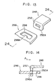
- a projection 298A is formed on the rear end side, i.e., the left side in Fig. 14, of the opening 298 of the tongue plate 296, and when sudden acceleration acts in the rightward direction as viewed in Fig. 14 (in the direction of arrow A in Fig. 14), this projection 298A is made to engage an elongated hole 252A provided in the hook 252 of the lock plate 248.
- the width (L2) of a rear end side 298B of the opening 298 of the tongue plate 296 is formed to be smaller than the width (L4) of a front end side 298C of the opening, and a large-width portion 252B is provided at a lower end of the hook 252 of the lock plate 248.
- the relationship between the width (L3) of this large-width portion 252B and the width (L1) of an upper portion of the hook 252 is set to be L1 ⁇ L2 ⁇ L3 ⁇ L4, whereby when sudden acceleration acts in the rightward direction as viewed in Fig. 15 (in the direction of arrow A in Fig.
- the tongue plate 296 moves in the direction of arrow A and assumes a position indicated by the two-dotted dash line.
- the large-width portion 252B of the lock plate 248 engages the rear end side 298B of the opening 298 of the tongue plate 296. In this case, it is possible to increase the strength of the lock plate 248.
- the present invention offers an outstanding advantage in that it is possible to maintain the locked state of the tongue plate even when an inertial force acts on the lock canceling means in the lock canceling direction.
Landscapes
- Buckles (AREA)
- Automotive Seat Belt Assembly (AREA)
Claims (8)
- Anschnallvorrichtung (110, 120) für den Gebrauch in einem Sitzgurtsystem mit:
einem Schnallenkörper (118, 122);
einer Zungenplatte (112, 296), die in den Schnallenkörper (118, 222) einführbar ist;
einem verschwenkbaren Verriegelungselement (128, 248), welches vom Schnallenkörper (118, 222) getragen wird und an der Zungenplatte (112, 296) zum Zwecke der Verriegelung angreift;
einem Entriegelungsmittel (154, 278), das vom Schnallenkörper (118, 222) getragen wird und in einer vorbestimmten Richtung bewegbar und derart ausgebildet ist, daß es das Verriegelungselement (128, 248) aus der Verriegelungslage in die entriegelte Lage verschwenkt; und einem Verriegelungshilfsmittel (162, 289), welches das Verriegelungselement (128, 248) hält, indem es in Einführrichtung der Zungenplatte (112, 296) im Schnallenkörper (118, 222) bewegbar ist,
dadurch gekennzeichnet, daß
eine zusätzliche Verriegelungsvorrichtung (168A, 170, 257A, 273, 275A, 254A, 252A, 298A, 252B, 298B, 172, 174) zum Verriegeln des schwenkbaren Verriegelungselements (128, 248) vorgesehen ist, wobei die zusätzliche Verriegelungsvorrichtung in Einführrichtung der Zungenplatte (112, 296) in den Schnallenkörper (118, 222) oder in Ausschubrichtung der Zungenplatte (112, 296) aus dem Schnallenkörper (118, 222) aufgrund einer in eine dieser Richtungen wirkenden Trägheitskraft bewegbar ist; und wobei diese zusätzliche Verriegelungsvorrichtung das verschwenkbare Verriegelungselement (128, 248) blockiert, sobald die Trägheitskraft auf die zusätzliche Verriegelungsvorrichtung einwirkt, so daß das verschwenkbare Verriegelungselement (128, 248) seinen Eingriffszustand mit der Zungenplatte (112, 296) beibehält. - Anschnallvorrichtung nach Anspruch 1, dadurch gekennzeichnet, daß das Entriegelungsmittel (154, 278) in einer Richtung im wesentlichen entlang der Einschubrichtung der Zungenplatte (112, 296) in den Schnallenkörper (118, 222) bewegbar ist und derart ausgebildet ist, daS es das Verriegelungshilfsmittel (162, 289) von dessen Halteposition in eine Position bewegt, in der das Verriegelungselement (128, 248) aus dessen Verriegelungslage in dessen entriegelte Lage verschwenken kann; und wobei die zusätzliche Verriegelungsvorrichtung eine Verschwenkung des Verriegelungselements (128, 248) aus der Verriegelungslage in die entriegelte Lage dann verhindert, wenn eine Trägheitskraft im wesentlichen in Einschubrichtung der Zungenplatte (112, 296) in den Schnallenkörper (118, 222) wirkt.
- Anschnallvorrichtung nach Anspruch 1 oder 2, dadurch gekennzeichnet, daß das Verriegelungselement (128) in Einschubrichtung der Zungenplatte in den Schnallenkörper (118) bewegbar ist und daß die zusätzliche Verriegelungsvorrichtung (174) mit einem eine Verschwenkung verhindernden Abschnitt versehen ist, der an dem Schnallenkörper (118) vorgesehen ist oder der zwischen dem Schnallenkörper (118) und dem Verriegelungselement (128) zwischengeschaltet ist und am Verriegelungselement (128) angreift oder bewirkt, daß der Schnallenkörper (118) am Verriegelungselement (128) angreift, welches in Einschubrichtung der Zungenplatte (112) in den Schnallenkörper (118) bewegt wird, wenn in Einschubrichtung der Zungenplatte (112) in den Schnallenkörper (118) die Trägheitskraft wirkt, wodurch eine Verschwenkung des Verriegelungselements (128) aus der ersten Lage in die zweite Lage verhindert wird.
- Anschnallvorrichtung nach Anspruch 1 oder 2, dadurch gekennzeichnet, daß das Verriegelungselement (128) in Einschubrichtung der Zungenplatte (112) in den Schnallenkörper bewegbar ist, und daß die zusätzliche Verriegelungsvorrichtung (172) von einem Vorsprung gebildet wird, der am Verriegelungselement (128) vorgesehen ist und in einer Richtung absteht, die rechtwinklig zu einer Ebene des Verschwenkweges des Verriegelungselements (128) liegt, und von einem eine Verschwenkung verhindernden Element (174) gebildet wird, welches am Schnallenkörper (118) vorgesehen ist und zum Vorsprung (172) des Verriegelungselements (128) korrespondiert und durch die in Einschubrichtung der Zungenplatte (112) in den Schnallenkörper wirkende Trägheitskraft in Einschubrichtung der Zungenplatte in den Schnallenkörper (118) bewegbar ist und derart ausgestaltet ist, daß eine Verschwenkung des Verriegelungselements (128) aus der ersten Lage in die zweite Lage verhindert wird.
- Anschnallvorrichtung nach einem der Ansprüche 1 oder 2, dadurch gekennzeichnet, daß außerdem ein Auswerfer (270) zum Drücken der in den Schnallenkörper (222) mittels eingeführter Zungenplatte (296) mittels einer in Gegenrichtung zur Einschubrichtung (A) der Zungenplatte (296) wirkenden Druckkraft vorgesehen ist, wobei die zusätzliche Verriegelungsvorrichtung (257A, 273A) einen ersten Vorsprung (273, 275) aufweist, der am Auswerfer (270) vorgesehen ist, und einen zweiten Vorsprung (257A, 254A) aufweist, der am Verriegelungselement (248) vorgesehen ist, und welcher dann am ersten Vorsprung (273) des Auswerfers (270) angreift, wenn dieser in Einschubrichtung der Zungenplatte (296) in den Schnallenkörper (222) bewegt wird, wenn die Trägheitskraft in Einschubrichtung der Zungenplatte (296) in den Schnallenkörper (222) wirkt, wodurch eine Verschwenkung des Verriegelungselements (248) aus der ersten in die zweite Lage verhindert wird.
- Anschnallvorrichtung nach Anspruch 1 oder 2, dadurch gekennzeichnet, daß die Zungenplatte (296) mit einer Öffnung (298) versehen ist, in welche ein Teil (252) des Verriegelungselements (248) eingeschoben ist, um eine Verbindung des Verriegelungselements (248) mit dieser herzustellen, und wobei die zusätzliche Verriegelungsvorrichtung (252A, 298A, 252B, 298B) zwischen die Öffnung (298) der Zungenplatte (296) und dem Teil (252) des Verriegelungselements (248) zwischengeschaltet ist und der Teil (252) des Verriegelungselements (248) dann an der Zungenplatte (296) angreift, wenn diese aufgrund der in Einschubrichtung der Zungenplatte (296) in den Schnallenkörper (222) wirkenden Trägheitskraft sich in Einschubrichtung der Zungenplatte (296) in den Schnallenkörper (222) bewegt, wodurch eine Verschwenkung des Verriegelungselements (248) aus der ersten Lage in die zweite Lage verhindert wird.
- Anschnallvorrichtung nach Anspruch 6, dadurch gekennzeichnet, daß die zusätzliche Verriegelungsvorrichtung (252A, 298A) einen Vorsprung (298A) aufweist, der von einem Randabschnitt der Öffnung (298) der Zungenplatte (296) absteht, und eine Öffnung (252A) aufweist, die in dem Teil (252) des Verriegelungselements (248)vorgesehen ist und in welches der Vorsprung (298A) eingeführt wird.
- Anschnallvorrichtung nach Anspruch 6, dadurch gekennzeichnet, daß die zusätzliche Verriegelungsvorrichtung (252B, 298B) einen Abschnitt (298B) mit einem kleinen Durchmesser aufweist, der in der Öffnung (298) der Zungenplatte (296) vorgesehen ist und einen Abschnitt (252B) mit einer großen Weite aufweist, die in dem Teil (252) des Verriegelungselements (248) vorgesehen ist und der an einem Randabschnitt des Abschnitts (298B) mit kleinem Durchmesser angreift.
Applications Claiming Priority (8)
| Application Number | Priority Date | Filing Date | Title |
|---|---|---|---|
| JP6946089 | 1989-06-14 | ||
| JP69460/89U | 1989-06-14 | ||
| JP22266589 | 1989-08-29 | ||
| JP222665/89 | 1989-08-29 | ||
| JP29145089 | 1989-11-09 | ||
| JP291450/89 | 1989-11-09 | ||
| JP103994/90 | 1990-04-19 | ||
| JP2103994A JP2653896B2 (ja) | 1989-06-14 | 1990-04-19 | バツクル装置 |
Publications (3)
| Publication Number | Publication Date |
|---|---|
| EP0402839A2 EP0402839A2 (de) | 1990-12-19 |
| EP0402839A3 EP0402839A3 (de) | 1991-03-27 |
| EP0402839B1 true EP0402839B1 (de) | 1994-12-28 |
Family
ID=27465132
Family Applications (1)
| Application Number | Title | Priority Date | Filing Date |
|---|---|---|---|
| EP90111031A Expired - Lifetime EP0402839B1 (de) | 1989-06-14 | 1990-06-12 | Anschnallvorrichtung |
Country Status (3)
| Country | Link |
|---|---|
| US (1) | US5054171A (de) |
| EP (1) | EP0402839B1 (de) |
| DE (2) | DE69015457T2 (de) |
Families Citing this family (24)
| Publication number | Priority date | Publication date | Assignee | Title |
|---|---|---|---|---|
| EP0485656B1 (de) * | 1990-11-15 | 1995-05-10 | TRW Occupant Restraint Systems GmbH | Schloss für Sicherheitsgurtsysteme in Fahrzeugen |
| DE9202525U1 (de) * | 1992-02-27 | 1992-04-16 | Autoliv Development AB, Vårgårda | Sicherheitsgurtschloß mit Verriegelungssperre |
| GB9204793D0 (en) * | 1992-03-05 | 1992-04-15 | Bsrd Ltd | Seat belt buckle |
| US5357658A (en) * | 1992-03-23 | 1994-10-25 | Kabushiki Kaisha Tokai-Rika-Denki Seisakusho | Buckle apparatus |
| EP0566856A1 (de) * | 1992-04-23 | 1993-10-27 | INDIANA MILLS & MANUFACTURING, INC. | Endlösende Schnalle mit schwenkbarer Sperrhakenbefreiung |
| DE4416138C2 (de) * | 1994-05-06 | 2002-06-13 | Trw Repa Gmbh | Verschluß für Sicherheitsgurte |
| GB9409246D0 (en) * | 1994-05-10 | 1994-06-29 | Alliedsignal Ltd | Buckle mechanism |
| DE4422224C2 (de) * | 1994-06-24 | 2003-06-26 | Opel Adam Ag | Sicherheitsgurtschloß |
| US5704099A (en) * | 1995-10-05 | 1998-01-06 | Trw Vehicle Safety Systems Inc. | Seat belt buckle with inertia locking mechanism |
| JP2001513339A (ja) * | 1997-08-04 | 2001-09-04 | ブリード オートモティブ テクノロジィ、 インク. | 安全ベルトのバックル |
| JP3809007B2 (ja) * | 1998-03-25 | 2006-08-16 | タカタ株式会社 | バックル |
| GB2338262B (en) * | 1998-06-10 | 2002-06-12 | Autoliv Dev | Improvements in or relating to a seat belt buckle |
| WO2001012007A1 (fr) * | 1999-08-13 | 2001-02-22 | Ashimori Industry Co., Ltd. | Dispositif pour boucle |
| JP3844179B2 (ja) | 1999-08-26 | 2006-11-08 | タカタ株式会社 | バックルおよびこれを備えたシートベルト装置 |
| DE20010535U1 (de) * | 2000-06-14 | 2000-10-26 | TRW Occupant Restraint Systems GmbH & Co. KG, 73553 Alfdorf | Strafferfestes Gurtschloß |
| US7370393B2 (en) * | 2004-09-20 | 2008-05-13 | Delphi Technologies, Inc. | Seat belt buckle for use with pretensioner |
| JP2006122553A (ja) * | 2004-11-01 | 2006-05-18 | Tokai Rika Co Ltd | バックル装置 |
| US20080093165A2 (en) * | 2005-01-26 | 2008-04-24 | The Hunter Safety System, Inc. | Fall-Arresting Safety Harness With An Improved Buckle |
| US7543363B2 (en) | 2005-05-26 | 2009-06-09 | Delphi Technologies, Inc. | Seat belt buckle for use with pretensioner |
| DE202007011066U1 (de) * | 2007-08-08 | 2007-10-18 | Key Safety Systems, Inc., Sterling Heights | Sicherheitsgurtschloss |
| JP5688256B2 (ja) * | 2009-10-28 | 2015-03-25 | 芦森工業株式会社 | バックル装置 |
| US8429799B2 (en) * | 2009-12-23 | 2013-04-30 | Key Safety Systems, Inc | Seat belt buckle |
| US9974365B2 (en) * | 2014-11-07 | 2018-05-22 | Ford Global Technologies, Llc | Buckle guide |
| US20220354222A1 (en) * | 2022-07-21 | 2022-11-10 | Biothane Coated Webbing Corp. | Seat belt buckle |
Family Cites Families (15)
| Publication number | Priority date | Publication date | Assignee | Title |
|---|---|---|---|---|
| GB1572106A (en) * | 1976-12-13 | 1980-07-23 | Wall Ltd Howard | Anchoring devices |
| NO138431C (no) * | 1977-02-25 | 1978-09-06 | Loyd S Industri As | Laas for sikkerhetsbelte. |
| SE7812170L (sv) * | 1977-12-07 | 1979-06-08 | Klippan Nv | Belteslas med lett frigorbar sperr |
| US4197619A (en) * | 1978-09-22 | 1980-04-15 | Britax (Wingard) Limited | Tongue and buckle fastener for a safety belt harness |
| US4377888A (en) * | 1979-12-19 | 1983-03-29 | Nsk-Warner K. K. | Buckle of a seat belt for a vehicle |
| JPS6239693Y2 (de) * | 1981-04-08 | 1987-10-09 | ||
| JPS5983409U (ja) * | 1982-11-30 | 1984-06-05 | 日本精工株式会社 | シ−トベルト用バツクル |
| JPS6048811U (ja) * | 1983-09-12 | 1985-04-05 | タカタ株式会社 | シ−トベルト用ラツチバツクル |
| US4562625A (en) * | 1983-12-21 | 1986-01-07 | Gateway Industries, Inc. | Seat belt buckle |
| DE3533684A1 (de) * | 1985-08-17 | 1987-02-26 | Autoflug Gmbh | Sicherheitsgurtverschluss |
| JPH0626167Y2 (ja) * | 1986-05-08 | 1994-07-20 | タカタ株式会社 | シートベルト用ラッチバックル |
| JPS6310911U (de) * | 1986-07-07 | 1988-01-25 | ||
| JPH0540727Y2 (de) * | 1987-03-24 | 1993-10-15 | ||
| GB2227513B (en) * | 1988-11-08 | 1993-02-10 | Gen Engineering | Improvements in or relating to a safety belt buckle |
| GB8904205D0 (en) * | 1989-02-23 | 1989-04-05 | Bsrd Ltd | Seat belt buckle |
-
1990
- 1990-06-11 US US07/535,582 patent/US5054171A/en not_active Expired - Lifetime
- 1990-06-12 DE DE69015457T patent/DE69015457T2/de not_active Expired - Lifetime
- 1990-06-12 DE DE199090111031T patent/DE402839T1/de active Pending
- 1990-06-12 EP EP90111031A patent/EP0402839B1/de not_active Expired - Lifetime
Also Published As
| Publication number | Publication date |
|---|---|
| DE69015457T2 (de) | 1995-05-11 |
| EP0402839A2 (de) | 1990-12-19 |
| DE402839T1 (de) | 1991-07-25 |
| US5054171A (en) | 1991-10-08 |
| EP0402839A3 (de) | 1991-03-27 |
| DE69015457D1 (de) | 1995-02-09 |
Similar Documents
| Publication | Publication Date | Title |
|---|---|---|
| EP0402839B1 (de) | Anschnallvorrichtung | |
| JP2587877Y2 (ja) | シートベルト用バックル装置 | |
| US6701587B1 (en) | Buckle device | |
| JP2825786B2 (ja) | 安全ベルトのためのバックル | |
| EP0368277B1 (de) | Schloss für Sicherheitsgurt | |
| US7426774B2 (en) | Buckle device | |
| CN103260963A (zh) | 带扣及具备该带扣的座椅安全带装置 | |
| US6266855B1 (en) | Seat belt buckle | |
| JPS6228890Y2 (de) | ||
| KR100233993B1 (ko) | 시이트 벨트 장치에 있어서의 버클장치 | |
| US5784766A (en) | Buckle mechanism | |
| US5974638A (en) | Seat belt buckle | |
| CN116548707A (zh) | 带扣装置 | |
| JP6764365B2 (ja) | シートベルト装置用タング及びスナップフィット構造 | |
| EP0907332B1 (de) | Sitzgurtverschluss | |
| US4885825A (en) | Buckle apparatus | |
| US4642858A (en) | Buckle apparatus | |
| US4420172A (en) | Ring joint for seatbelt system | |
| US7458136B2 (en) | Shock-absorbing safety belt buckle | |
| JP2653896B2 (ja) | バツクル装置 | |
| JPH018179Y2 (de) | ||
| JPH05278564A (ja) | 安全ベルト用バックル | |
| JPH0744165Y2 (ja) | タングプレート | |
| JP6742264B2 (ja) | シートベルト装置用タング | |
| JP3207871U (ja) | チャイルドシート用の超簡単ベルト通し |
Legal Events
| Date | Code | Title | Description |
|---|---|---|---|
| PUAI | Public reference made under article 153(3) epc to a published international application that has entered the european phase |
Free format text: ORIGINAL CODE: 0009012 |
|
| AK | Designated contracting states |
Kind code of ref document: A2 Designated state(s): DE FR GB SE |
|
| PUAL | Search report despatched |
Free format text: ORIGINAL CODE: 0009013 |
|
| 17P | Request for examination filed |
Effective date: 19901217 |
|
| AK | Designated contracting states |
Kind code of ref document: A3 Designated state(s): DE FR GB SE |
|
| EL | Fr: translation of claims filed | ||
| DET | De: translation of patent claims | ||
| 17Q | First examination report despatched |
Effective date: 19920805 |
|
| GRAA | (expected) grant |
Free format text: ORIGINAL CODE: 0009210 |
|
| AK | Designated contracting states |
Kind code of ref document: B1 Designated state(s): DE FR GB SE |
|
| EAL | Se: european patent in force in sweden |
Ref document number: 90111031.2 |
|
| REF | Corresponds to: |
Ref document number: 69015457 Country of ref document: DE Date of ref document: 19950209 |
|
| ET | Fr: translation filed | ||
| PLBE | No opposition filed within time limit |
Free format text: ORIGINAL CODE: 0009261 |
|
| STAA | Information on the status of an ep patent application or granted ep patent |
Free format text: STATUS: NO OPPOSITION FILED WITHIN TIME LIMIT |
|
| 26N | No opposition filed | ||
| REG | Reference to a national code |
Ref country code: GB Ref legal event code: IF02 |
|
| PGFP | Annual fee paid to national office [announced via postgrant information from national office to epo] |
Ref country code: SE Payment date: 20090605 Year of fee payment: 20 |
|
| PGFP | Annual fee paid to national office [announced via postgrant information from national office to epo] |
Ref country code: GB Payment date: 20090610 Year of fee payment: 20 Ref country code: DE Payment date: 20090604 Year of fee payment: 20 |
|
| REG | Reference to a national code |
Ref country code: GB Ref legal event code: PE20 Expiry date: 20100611 |
|
| EUG | Se: european patent has lapsed | ||
| PG25 | Lapsed in a contracting state [announced via postgrant information from national office to epo] |
Ref country code: GB Free format text: LAPSE BECAUSE OF EXPIRATION OF PROTECTION Effective date: 20100611 |
|
| PG25 | Lapsed in a contracting state [announced via postgrant information from national office to epo] |
Ref country code: DE Free format text: LAPSE BECAUSE OF EXPIRATION OF PROTECTION Effective date: 20100612 |
|
| PGFP | Annual fee paid to national office [announced via postgrant information from national office to epo] |
Ref country code: FR Payment date: 20090611 Year of fee payment: 20 |