EP0401497A2 - Haltegriff, insbesondere für Fahrzeuge - Google Patents
Haltegriff, insbesondere für Fahrzeuge Download PDFInfo
- Publication number
- EP0401497A2 EP0401497A2 EP90107213A EP90107213A EP0401497A2 EP 0401497 A2 EP0401497 A2 EP 0401497A2 EP 90107213 A EP90107213 A EP 90107213A EP 90107213 A EP90107213 A EP 90107213A EP 0401497 A2 EP0401497 A2 EP 0401497A2
- Authority
- EP
- European Patent Office
- Prior art keywords
- handle
- core
- opening
- decorative cap
- molded
- Prior art date
- Legal status (The legal status is an assumption and is not a legal conclusion. Google has not performed a legal analysis and makes no representation as to the accuracy of the status listed.)
- Granted
Links
Images
Classifications
-
- B—PERFORMING OPERATIONS; TRANSPORTING
- B60—VEHICLES IN GENERAL
- B60N—SEATS SPECIALLY ADAPTED FOR VEHICLES; VEHICLE PASSENGER ACCOMMODATION NOT OTHERWISE PROVIDED FOR
- B60N3/00—Arrangements or adaptations of other passenger fittings, not otherwise provided for
- B60N3/02—Arrangements or adaptations of other passenger fittings, not otherwise provided for of hand grips or straps
- B60N3/026—Arrangements or adaptations of other passenger fittings, not otherwise provided for of hand grips or straps characterised by the fixing means
Definitions
- the invention relates to a handle, in particular for vehicles, with a bow-shaped handle body, which consists of a core provided with a tubular cover, the angled, cover-free end regions of which can be fastened to a vehicle body, each fastening region being coverable with a decorative cap.
- a handle of the generic type is shown in DE-OS 15 30 987.
- the fastening areas can be covered by decorative caps which are arranged displaceably on the handle, and are held on the handle feet by means of clamping strips.
- a disadvantage of this known handle is that the decorative caps covering the fastening areas are relatively thick and protrude from the fastening surface. It is also difficult to clip the decorative caps onto the terminal strips of the handle feet if the handle is to be arranged in areas of a vehicle which are provided with an elastic vehicle lining, such as a finished roof lining. The vehicle lining must either be sufficiently compressible to reliably clasp the trim to ensure caps, or be punched out, but this affects the pleasing appearance, because then unsightly gaps and joints arise.
- the present invention is based on the object of designing a handle of the type mentioned in such a way that it can be arranged advantageously in the interior of a vehicle, in particular where there is an elastic vehicle lining, primarily a finished roof lining, furthermore in particular a vehicle lining or the aim is to attach the handle that is flush with the roof lining.
- the handle should be designed so that the edges of punched holes in the vehicle lining, which are penetrated by the end regions of the core during the handle attachment, are reliably covered.
- each end region of the core is equipped with a shaped body, which consists of a base plate resting on the end region of the core and fastened thereon and a head plate connected thereto via walls and spaced from the base plate, the latter being one of one Collar has framed opening into which an end portion of the handle body is immersed and which is otherwise closable by the decorative cap collar.
- the object is achieved in an optimal manner. It is essential that a surface-flush handle attachment could be achieved so that only the handle bar projects beyond the vehicle lining. Furthermore, it is essential that the edge areas surrounding the punched-out areas in the vehicle lining are forced in the direction of the body by the shaped bodies or their head plates arranged at the end areas of the core, so that the decorative cap is completely relieved. According to the invention, the collar of the head plate is provided for covering an edge area surrounding an assembly opening in an elastic vehicle lining, such as a finished roof lining. This enables a relatively large tolerance compensation (tolerances can easily occur in the interaction between punched-outs in the body and those in the vehicle lining part).
- the molded body is designed as a plastic injection molded part and is therefore simple and inexpensive to produce.
- the molded body can be fastened to the core by means of a hollow rivet which penetrates this and a bore in the end region of the core and can have an integrally formed pin which penetrates a second bore in the end region of the core as anti-rotation protection, especially since the pin should also penetrate an opening in the body wall.
- the molded body can have a one-piece molded, material flap extending the base plate, which is formed on the base plate by means of a film hinge in such a way that it can be folded around the free end of the end region of the core in order to reach under the end region, the material flap having a first opening for passage of the pin, a second opening for passage of the hollow rivet and further molded clip elements which grip around the bottom plate.
- the material flap having a first opening for passage of the pin, a second opening for passage of the hollow rivet and further molded clip elements which grip around the bottom plate.
- the decorative cap of the handle according to the invention is preferably designed as a separate plastic injection-molded part and has on one end a one-piece molded locking lug which can be snapped into a wall opening in the molded body and on the other hand two opposing, integrally molded-on clip elements for snapping the opening edge of the head plate behind.
- the opening edge of the head plate has a step-like offset which supports the decorative cap.
- the decorative cap is also hollow at one end, in adaptation to the end region of the handle body which plunges into the opening of the shaped body.
- the decorative cap is held captive on the shaped body, in that it is provided that the decorative cap has on the underside an integrally molded band body with an anchor-shaped end region inserted through the wall opening of the shaped body.
- a further development of the invention can consist in the fact that the end region of the handle body which plunges into the opening of the molded body is supported by an obliquely aligned wall of the molded body which is adapted to its shape. This ensures, in addition to a good appearance of the handle, at the same time that the nails or pins, by means of which the tubular coating is fixed at both ends of the core, cannot come loose or slip out.
- the new handle is intended in particular for arrangement on the roof area of a vehicle and is intended to span a vehicle lining, in particular a finished roof lining.
- the new handle consists of a core 2 provided with a tubular cover 1, the angled, cover-free end regions 3 of which can be fastened to a vehicle body 4.
- the coating 1 can be made of a foamed plastic material and the core 2 can be formed from a steel strip.
- Each end region 3 of the core 2 is equipped with a molded body 5 designed as a plastic injection molded part.
- the molded body 5 comprises a base plate 6, walls 7 and a top plate 8.
- the base plate 6 is formed with a material tab 9 that extends this, a film hinge 10 being provided as a connection between the base plate 6 and the material tab 9.
- the base plate 6 has a hole 11 and an integrally formed, downwardly directed pin 12.
- the material tab 9 is formed with a first hole 13, a second hole 14 and with molded-on clip elements 15 on the edge.
- the base plate 6 is placed on the end region 3 of the core 2, which has holes that are aligned with the hole 11 and the pin 12.
- the material flap 9 is pivoted around the free end of the end area, so that the pin 12 can penetrate the hole 14 and the clip elements 15 are able to overlap the base plate 6.
- the base plate 6 and the material flap 9 are additionally fixed to the end region 3 of the core 2, specifically by means of a hollow rivet 16, which also serves to carry out a fastening element 17, here designed as a screw, for fixing the handle on the vehicle body 4.
- the head plate 8 which is connected to the base plate 6 at a distance via the walls 7, is essentially formed by a collar 18 framing an opening of the molded body 5.
- this collar 18 lies on the edge region 21 of the finished roof that delimits a cut-out 19 in the finished roof 20 and pulls this edge region 21 towards the vehicle body when the handle is screwed on, as shown, so that a handle fastening which is flush with the roof surface is present. This measure also keeps the headlining in the area of each handle attachment point.
- the opening of the molded body 5 receives the end region of the handle, the fastening element 17 and the decorative cap 22.
- the decorative cap 22 is a separately manufactured plastic injection molded part and essentially has the shape of a flat lid.
- the decorative cap 22 has on one end an integrally molded locking lug 24 which can be snapped into a wall opening 23 of the molded body 5 and on the other hand two opposing, integrally molded clip elements 25 for snapping the opening edge of the head plate 8 backwards.
- a support web 26 is formed on a wall 7 of the molded body 5.
- the opening edge of the head plate 8 is formed with a stepped shoulder 27 that supports the decorative cap 22.
- the decorative cap has one end, in adaptation to the end region of the handle body which plunges into the opening of the molded body 5, as in particular from FIG. 2 can be seen, hollow-round.
- the decorative cap 22 is captively attached to the molded body 5, for which purpose it is formed in one piece with a band strip 28, the free end of which is designed as an anchor 29 and inserted through the wall opening 23.
- the end area of the handle body 50 which is immersed in the opening of the shaped body 5 is supported by an obliquely aligned wall 7 of the shaped body 5 which is adapted to its shape, which also results in a securing of the nail 30 fixing the coating 1 to the core.
Abstract
Description
- Die Erfindung bezieht sich auf einen Haltegriff, insbesondere für Fahrzeuge, mit einem bügelförmigen Griffkörper, der aus einem mit einem schlauchartigen Überzug versehenen Kern besteht, dessen abgewinkelte, überzugsfreie Endbereiche an einer Fahrzeugkarosserie befestigbar sind, wobei jeder Befestigungsbereich mit einer Zierkappe abdeckbar ist.
- Ein Haltegriff der gattungsgemäßen Art ist in der DE-OS 15 30 987 gezeigt. Bei diesem bekannten Haltegriff sind die Befestigungsbereiche durch auf dem Griffbügel verschiebbar angeordnete Zierkappen abdeckbar, deren Halterung an den Griff-Füßen durch Klemmleisten erfolgt. Als nachteilig wird bei diesem bekannten Haltegriff empfunden, daß die die Befestigungsbereiche abdeckenden Zierkappen relativ stark auftragen und von der Befestigungsfläche abstehen. Auch ist das Aufklipsen der Zierkappen auf die Klemmleisten der Griff-Füße dann schwierig, wenn der Haltegriff in Bereichen eines Fahrzeuges anzuordnen ist, welche mit einer elastischen Fahrzeugauskleidung, wie Fertighimmel, versehen sind. Dabei muß die Fahrzeugauskleidung entweder genügend kompressibel sein, um ein zuverlässiges Verklipsen der Zier kappen zu gewährleisten, oder mit Ausstanzungen versehen werden, worunter aber das gefällige Aussehen leidet, weil dann unschöne Spalten und Fugen entstehen.
- Der vorliegenden Erfindung liegt nun die Aufgabe zugrunde, einen Haltegriff der eingangs genannten Art so zu gestalten, daß er im Innenbereich eines Fahrzeuges insbesondere dort mit Vorteil anordbar ist, wo sich eine elastische Fahrzeugauskleidung, vornehmlich ein Fertighimmel befindet, wobei weiterhin insbesondere eine fahrzeugauskleidungs- bzw. dachhimmeloberflächenbündige Haltegriffbefestigung angestrebt wird. Weiterhin soll der Haltegriff so gestaltet sein, daß die Ränder von Ausstanzungen in der Fahrzeugauskleidung, die von den Endbereichen des Kerns bei der Haltegriffbefestigung durchgriffen werden, eine zuverlässige Abdeckung erfahren.
- Diese Aufgabe wird erfindungsgemäß dadurch gelöst, daß jeder Endbereich des Kerns mit einem Formkörper bestückt ist, welcher aus einer auf dem Endbereich des Kerns aufliegenden und daran befestigten Bodenplatte und einer damit über Wände verbundenen, von der Bodenplatte beabstandeten Kopfplatte besteht, welch letztere eine von einem Kragen umrahmte Öffnung aufweist, in die ein Endbereich des Griffkörpers eintaucht und die im übrigen durch die Zierkappe kragenbündig verschließbar ist.
- Durch diese erfindungsgemäßen Maßnahmen wird die gestellte Aufgabe in optimaler Weise gelöst. Dabei ist es wesentlich, daß eine oberflächenbündige Haltegriffbefestigung erzielt werden konnte, so daß nur noch der Griffbügel die Fahrzeugauskleidung überragt. Weiterhin ist es wesentlich, daß die die Ausstanzungen in der Fahrzeugauskleidung umgebenen Randbereiche durch die an den Endbereichen des Kerns angeordneten Formkörper bzw. deren Kopfplatten in Richtung zur Karosserie gezwungen werden, so daß die Zierkappe insoweit völlig entlastet ist. Gemäß der Erfindung ist der Kragen der Kopfplatte zum Abdecken eines, eine Montageöffnung in einer elastischen Fahrzeugauskleidung, wie Fertighimmel, umgebenden Randbereich vorgesehen. Dadurch wird ein relativ großer Toleranzausgleich (Toleranzen können leicht im Zusammenspiel zwischen Ausstanzungen in der Karosserie und solchen im Fahrzeugauskleidungsteil auftreten) ermöglicht.
- In Ausgestaltung der ,Erfindung ist der Formkörper als Kunststoff-Spritzgußteil ausgebildet und daher einfach und kostengünstig herstellbar. Der Formkörper kann mittels eines diesen und eine Bohrung im Endbereich des Kerns durchsetzenden Hohlniets am Kern befestigt sein und einen einstückig angeformten, eine zweite Bohrung im Endbereich des Kerns -durchsetzenden Zapfen als Verdrehschutz aufweisen, zumal der Zapfen auch eine Öffnung in der Karosseriewand durchdringen soll.
- Weiterhin kann der Formkörper einen einteilig angeformten, die Bodenplatte verlängernden Materiallappen aufweisen, der über ein Filmscharnier so an der Bodenplatte angeformt ist, daß er um das freie Ende des Endbereichs des Kerns herumklappbar ist, um den Endbereich zu untergreifen, wobei der Materiallappen eine erste Öffnung zum Durchlassen des Zapfens, eine zweite Öffnung zum Durchlassen des Hohlniets und weiterhin angeformte Klipselemente aufweist, die die Bodenplatte randseitig umgreifen. Auf diese Weise wird eine unmittelbare Anlage des abgewinkelten Endbereichs des Kerns auf dem Karosserieblech vermieden, was insbesondere dann von Vorteil ist, wenn der Kern des Griffteils aus einem Stahlband gebildet ist.
- Die Zierkappe des erfindungsgemäßen Haltegriffs ist bevorzugterweise als separates Kunststoff-Spritzgußteil ausgeführt und weist einendig eine einstückig angeformte, in einem Wanddurchbruch des Formkörpers einrastbare Rastnase und anderendig zwei einander gegenüberliegende, einstückig angeformte Klipselemente zum Hinterrasten des Öffnungsrandes des Kopfplatte auf. Für den bündigen Abschluß der Zierkappe weist der Öffnungsrand der Kopfplatte eine die Zierkappe abstützende, stufenförmige Absetzung auf. Auch ist die Zierkappe einendig, in Anpassung an den, in die Öffnung des Formkörpers eintauchenden Endbereich des Griffkörpers, hohlrund ausgebildet. Ferner ist die Zierkappe unverlierbar am Formkörper gehalten, indem vorgesehen ist, daß die Zierkappe unterseitig einen einstückig angeformten, durch den Wanddurchbruch des Formkörpers gesteckten Bandkörper mit ankerförmigen Endbereich aufweist. Der Vorteil dieser Maßnahme ist zum einen darin zu sehen, daß sämtliche Teile des erfindungsgemäßen Haltegriffs zu einer Montageeinheit zusammengefaßt sind und ist zum anderen darin begründet, daß eine Farbechtheit zwischen Formteil einerseits und Zierkappe andererseits leicht eingehalten werden kann, zumal es ohne weiteres möglich ist, diese Teile jeweils in einem Schuß zu spritzen.
- Schließlich kann eine Weiterbildung der Erfindung noch darin bestehen, daß der in die Öffnung des Formkörpers eintauchende Endbereich des Griffkorpers durch eine seiner Form angepaßten, schräg ausgerichteten Wandung des Formkörpers abgestützt ist. Hierdurch wird neben einem guten Aussehen des Haltegriffs gleichzeitig sichergestellt, daß sich die Nägel oder Zapfen, mittels denen der schlauchartige Überzug beidendig am Kern festgelegt ist, nicht lösen oder herausrutschen können.
- Ein Ausführungsbeispiel der Erfindung wird im folgenden anhand der Zeichnung näher erläutert. Es zeigen
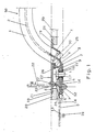
- Fig. 1 einen Endbereich des Haltegriffes im Längsschnitt gesehen und
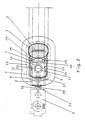
- Fig. 2 eine Draufsicht auf den Haltegriff nach Fig. 1.
- Der neue Haltegriff ist insbesondere zur Anordnung am Dachbereich eines Fahrzeuges bestimmt und soll eine Fahrzeugauskleidung, insbesondere einen Fertighimmel, überspannen.
- Im einzelnen besteht der neue Haltegriff aus einem mit einem schlauchartigen Überzug 1 versehenen Kern 2, dessen abgewinkelte, überzugsfreie Endbereiche 3 an einer Fahrzeugkarosserie 4 befestigbar sind. Der Überzug 1 kann aus einem aufgeschäumten Kunststoffmaterial und der Kern 2 kann aus einem Stahlband gebildet sein.
- Jeder Endbereich 3 des Kerns 2 ist mit einem als Kunststoff-Spritzgußteil ausgebildeten Formkörper 5 bestückt. Der Formkörper 5 umfaßt eine Bodenplatte 6, Wände 7 und eine Kopfplatte 8. Die Bodenplatte 6 ist mit einem diese verlängernden Materiallappen 9 ausgebildet, wobei als Verbindung zwischen der Bodenplatte 6 und dem Materiallappen 9 ein Filmscharnier 10 vorgesehen ist. Die Bodenplatte 6 weist einen Lochdurchzug 11 und einen angeformten, nach unten gerichteten Zapfen 12 auf. Der Materiallappen 9 ist mit einem ersten Lochdurchzug 13, einem zweiten Lochdurchzug 14 und mit randseitig angeformten Klipselementen 15 ausgebildet.
- Zur Festlegung des Formkörpers 5 am Kern 2 wird die Bodenplatte 6 auf dem Endbereich 3 des Kerns 2 aufgelegt, der mit dem Lochdurchzug 11 und dem Zapfen 12 fluchtende Bohrungen aufweist. Nach dem Einsetzen des Zapfens 12 in die entsprechende Bohrung des Endbereichs 3 wird der Materiallappen 9 um das freie Ende des Endbereichs herumgeschwenkt, so daß der Zapfen 12 den Lochdurchzug 14 zu durchsetzen vermag und die Klipselemente 15 die Bodenplatte 6 zu übergreifen vermögen. Alsdann werden die Bodenplatte 6 und der Materiallappen 9 zusätzlich am Endbereich 3 des Kerns 2 festgelegt, und zwar durch einen Hohlniet 16, der auch zum Durchführen eines, hier als Schraube ausgeführten Befestigungselements 17 für die Festlegung des Haltegriffes an der Fahrzeugkarosserie 4 dient.
- Die über die Wände 7 mit der Bodenplatte 6 mit Abstand verbundene Kopfplatte 8 wird im wesentlichen durch einen, eine Öffnung des Formkörpers 5 umrahmenden Kragen 18 gebildet. Dieser Kragen 18 legt sich bei der Montage des Haltegriffs auf den, eine Ausstanzung 19 im Fertighimmel 20 begrenzenden Randbereich 21 des Fertighimmels auf und zieht diesen Randbereich 21, beim Anschrauben des Haltegriffes, wie dargestellt, in Richtung zur Fahrzeugkarosserie ein, so daß eine dachhimmeloberflächenbündige Haltegriffbefestigung vorliegt. Zusätzlich wird der Dachhimmel durch diese Maßnahme im Bereich jeder Griffbefestigungsstelle gehalten.
- Die Öffnung des Formkörpers 5 nimmt den Endbereich des Griffbügels, des Befestigungselements 17 sowie die Zierkappe 22 auf. Die Zierkappe 22 ist ein separat gefertigtes Kunststoff-Spritzgußteil und besitzt im wesentlichen die Form eines flachen Deckels. Die Zierkappe 22 weist einendig eine einstückig angeformte, in einen Wanddurchbruch 23 des Formkörpers 5 einrastbare Rastnase 24 und anderendig zwei einander gegenüberliegende, einstückig angeformte Klipselemente 25 zum Hinterrasten des Öffnungsrandes der Kopfplatte 8 auf. Zudem ist ein sich an einer Wand 7 des Formkörpers 5 anlegender Stützsteg 26 angeformt. Der Öffnungsrand der Kopfplatte 8 ist mit einer, die Zierkappe 22 abstützenden, stufenförmigen Absetzung 27 ausgebildet. Die Zierkappe ist einendig, in Anpassung an den, in die Öffnung des Formkörpers 5 eintauchenden Endbereich des Griffkörpers, wie insbesondere aus Fig. 2 ersichtlich ist, hohlrund ausgebildet. Die Zierkappe 22 ist am Formkörper 5 unverlierbar festgelegt, wozu sie mit einem Bandstreifen 28 einstückig ausgebildet ist, dessen freies Ende als Anker 29 gestaltet und durch den Wanddurchbruch 23 gesteckt ist.
- Wie die Zeichnung weiterhin erkennen läßt, ist der in die Öffnung des Formkörpers 5 eintauchende Endbereich des Griffkörpers 50 durch eine seiner Form angepaßten schrägausgerichteten Wandung 7 des Formkörpers 5 abgestützt, wodurch sich auch eine Sicherung des den Überzug 1 am Kern festlegenden Nagels 30 ergibt.
Claims (10)
Applications Claiming Priority (2)
| Application Number | Priority Date | Filing Date | Title |
|---|---|---|---|
| DE3918425 | 1989-06-06 | ||
| DE3918425A DE3918425A1 (de) | 1989-06-06 | 1989-06-06 | Haltegriff, insbesondere fuer fahrzeuge |
Publications (3)
| Publication Number | Publication Date |
|---|---|
| EP0401497A2 true EP0401497A2 (de) | 1990-12-12 |
| EP0401497A3 EP0401497A3 (de) | 1991-08-07 |
| EP0401497B1 EP0401497B1 (de) | 1994-07-20 |
Family
ID=6382173
Family Applications (1)
| Application Number | Title | Priority Date | Filing Date |
|---|---|---|---|
| EP90107213A Expired - Lifetime EP0401497B1 (de) | 1989-06-06 | 1990-04-14 | Haltegriff, insbesondere für Fahrzeuge |
Country Status (3)
| Country | Link |
|---|---|
| EP (1) | EP0401497B1 (de) |
| DE (2) | DE3918425A1 (de) |
| ES (1) | ES2056287T3 (de) |
Families Citing this family (2)
| Publication number | Priority date | Publication date | Assignee | Title |
|---|---|---|---|---|
| DE20016696U1 (de) * | 2000-09-27 | 2002-02-14 | Niemann Hans Dieter | Kunststoff-Balkontürgriff |
| DE102005003761A1 (de) * | 2005-01-27 | 2006-08-10 | Happich Fahrzeug- Und Industrieteile Gmbh | Abdeckeinrichtung, insbesondere für Haltegriffe von Fahrzeugen |
Citations (11)
| Publication number | Priority date | Publication date | Assignee | Title |
|---|---|---|---|---|
| GB1160887A (en) * | 1965-09-15 | 1969-08-06 | Happich Gmbh Gebr | A Hold, more particularly a Handhold for Vehicles |
| DE1530987A1 (de) * | 1967-02-18 | 1970-09-24 | Bolta Werke Gmbh | Haltegriff,insbesondere fuer Kraftfahrzeuge |
| FR2073778A5 (de) * | 1969-12-20 | 1971-10-01 | Happich Gmbh Gebr | |
| DE1779991A1 (de) * | 1966-01-28 | 1973-04-19 | Happich Gmbh Gebr | Griff, insbesondere haltegriff fuer kraftfahrzeuge |
| FR2279584A1 (fr) * | 1974-07-24 | 1976-02-20 | Daimler Benz Ag | Dispositif de fixation de poignee interieure de vehicule |
| DE2709185A1 (de) * | 1977-03-03 | 1978-09-07 | Happich Gmbh Gebr | Fahrzeugsitz mit griff-ascher-set |
| DE2718402A1 (de) * | 1977-04-26 | 1978-11-09 | Happich Gmbh Gebr | Griff, insbesondere haltegriff fuer fahrzeuge |
| GB2023077A (en) * | 1978-06-12 | 1979-12-28 | Happich Gmbh Gebr | Grip handle e.g. for a motor vehicle |
| EP0097219A2 (de) * | 1982-06-18 | 1984-01-04 | Gebr. Happich GmbH | Haltegriff od. dgl. für Fahrzeuge |
| DE3607744A1 (de) * | 1986-03-08 | 1987-09-17 | Daimler Benz Ag | Haltegriff mit kleiderhaken fuer kraftfahrzeuge |
| DE3928871A1 (de) * | 1988-09-07 | 1990-03-08 | Volkswagen Ag | Haltegriff, insbesondere fuer kraftfahrzeuginsassen |
Family Cites Families (1)
| Publication number | Priority date | Publication date | Assignee | Title |
|---|---|---|---|---|
| DE1655579B1 (de) * | 1967-01-23 | 1971-10-21 | Volkswagenwerk Ag | Haltebuegel fuer Kraftfahrzeuge |
-
1989
- 1989-06-06 DE DE3918425A patent/DE3918425A1/de not_active Withdrawn
-
1990
- 1990-04-14 EP EP90107213A patent/EP0401497B1/de not_active Expired - Lifetime
- 1990-04-14 ES ES90107213T patent/ES2056287T3/es not_active Expired - Lifetime
- 1990-04-14 DE DE59006476T patent/DE59006476D1/de not_active Expired - Fee Related
Patent Citations (11)
| Publication number | Priority date | Publication date | Assignee | Title |
|---|---|---|---|---|
| GB1160887A (en) * | 1965-09-15 | 1969-08-06 | Happich Gmbh Gebr | A Hold, more particularly a Handhold for Vehicles |
| DE1779991A1 (de) * | 1966-01-28 | 1973-04-19 | Happich Gmbh Gebr | Griff, insbesondere haltegriff fuer kraftfahrzeuge |
| DE1530987A1 (de) * | 1967-02-18 | 1970-09-24 | Bolta Werke Gmbh | Haltegriff,insbesondere fuer Kraftfahrzeuge |
| FR2073778A5 (de) * | 1969-12-20 | 1971-10-01 | Happich Gmbh Gebr | |
| FR2279584A1 (fr) * | 1974-07-24 | 1976-02-20 | Daimler Benz Ag | Dispositif de fixation de poignee interieure de vehicule |
| DE2709185A1 (de) * | 1977-03-03 | 1978-09-07 | Happich Gmbh Gebr | Fahrzeugsitz mit griff-ascher-set |
| DE2718402A1 (de) * | 1977-04-26 | 1978-11-09 | Happich Gmbh Gebr | Griff, insbesondere haltegriff fuer fahrzeuge |
| GB2023077A (en) * | 1978-06-12 | 1979-12-28 | Happich Gmbh Gebr | Grip handle e.g. for a motor vehicle |
| EP0097219A2 (de) * | 1982-06-18 | 1984-01-04 | Gebr. Happich GmbH | Haltegriff od. dgl. für Fahrzeuge |
| DE3607744A1 (de) * | 1986-03-08 | 1987-09-17 | Daimler Benz Ag | Haltegriff mit kleiderhaken fuer kraftfahrzeuge |
| DE3928871A1 (de) * | 1988-09-07 | 1990-03-08 | Volkswagen Ag | Haltegriff, insbesondere fuer kraftfahrzeuginsassen |
Also Published As
| Publication number | Publication date |
|---|---|
| EP0401497A3 (de) | 1991-08-07 |
| DE3918425A1 (de) | 1990-12-13 |
| EP0401497B1 (de) | 1994-07-20 |
| DE59006476D1 (de) | 1994-08-25 |
| ES2056287T3 (es) | 1994-10-01 |
Similar Documents
| Publication | Publication Date | Title |
|---|---|---|
| DE4309088C2 (de) | Ortsfest einbaubare Scheibe für Kraftfahrzeuge | |
| EP0487965A1 (de) | Zweiteiliger Halteclip zur Befestigung von Schutz- oder Zierleisten | |
| EP0517057B1 (de) | Verkleidung für Rahmen von Fenstern, Türen od.dgl. | |
| DE4318534A1 (de) | Haltedübel | |
| DE3115117A1 (de) | Anordnung zur anbringung von funktionsteilen an einem abschliessbaren fahrzeugelement | |
| WO1990008667A1 (de) | Vorrichtung zur befestigung eines dachhimmels am dachrahmen einer schiebedach- oder schiebehebedachkonstruktion | |
| DE10050322A1 (de) | Türmodulträger | |
| DE10359768A1 (de) | Fahrzeugkarosserie | |
| EP1033270A2 (de) | Klappverdeck für Kraftfahrzeuge mit einem äusseren Verdeckbezug und einem Himmel sowie mit mindestens einer im äusseren Verdeckbezug angeordneten Scheibe | |
| DE19625632A1 (de) | Gepäckträger für Fahrzeuge | |
| DE3902399A1 (de) | Zierleistenhalter | |
| DE3243802A1 (de) | Ablageschale mit deckel, insbesondere zur aufnahme von verbandsmaterial | |
| EP0675295B1 (de) | Befestigungsvorrichtung | |
| DE10048774A1 (de) | Türelement und Verfahren zur Montage des Türelementes | |
| DE2856493A1 (de) | Zierleistenklemme | |
| EP0241660A2 (de) | Grundplatte zur Befestigung eines Scharnierarms eines Möbelscharniers o. dgl. | |
| DE2921956A1 (de) | Befestigungsvorrichtung aus kunststoff | |
| DE2411240A1 (de) | Befestigungsvorrichtung | |
| EP0401497B1 (de) | Haltegriff, insbesondere für Fahrzeuge | |
| DE2718402A1 (de) | Griff, insbesondere haltegriff fuer fahrzeuge | |
| DE102019205830A1 (de) | Befestigungselement und Befestigungsanordnung für eine Kraftfahrzeugkarosserie | |
| DE10330888B3 (de) | Klemmvorrichtung für ein Kraftfahrzeug | |
| EP0593909A1 (de) | Kunststoff-Halteclip für Schutz-, Zierleisten oder dergleichen, insbesondere an Kraftfahrzeugen | |
| DE3136592A1 (de) | Schmutzabweiser fuer kraftfahrzeuge | |
| EP1064164A1 (de) | Dichtungsprofil für ein kraftfahrzeug |
Legal Events
| Date | Code | Title | Description |
|---|---|---|---|
| PUAI | Public reference made under article 153(3) epc to a published international application that has entered the european phase |
Free format text: ORIGINAL CODE: 0009012 |
|
| AK | Designated contracting states |
Kind code of ref document: A2 Designated state(s): BE DE ES FR GB IT SE |
|
| PUAL | Search report despatched |
Free format text: ORIGINAL CODE: 0009013 |
|
| AK | Designated contracting states |
Kind code of ref document: A3 Designated state(s): BE DE ES FR GB IT SE |
|
| 17P | Request for examination filed |
Effective date: 19910701 |
|
| 17Q | First examination report despatched |
Effective date: 19930902 |
|
| GRAA | (expected) grant |
Free format text: ORIGINAL CODE: 0009210 |
|
| AK | Designated contracting states |
Kind code of ref document: B1 Designated state(s): BE DE ES FR GB IT SE |
|
| GBT | Gb: translation of ep patent filed (gb section 77(6)(a)/1977) |
Effective date: 19940725 |
|
| REF | Corresponds to: |
Ref document number: 59006476 Country of ref document: DE Date of ref document: 19940825 |
|
| ITF | It: translation for a ep patent filed |
Owner name: BUGNION S.P.A. |
|
| REG | Reference to a national code |
Ref country code: ES Ref legal event code: FG2A Ref document number: 2056287 Country of ref document: ES Kind code of ref document: T3 |
|
| ET | Fr: translation filed | ||
| EAL | Se: european patent in force in sweden |
Ref document number: 90107213.2 |
|
| PLBE | No opposition filed within time limit |
Free format text: ORIGINAL CODE: 0009261 |
|
| STAA | Information on the status of an ep patent application or granted ep patent |
Free format text: STATUS: NO OPPOSITION FILED WITHIN TIME LIMIT |
|
| 26N | No opposition filed | ||
| REG | Reference to a national code |
Ref country code: ES Ref legal event code: PC2A |
|
| REG | Reference to a national code |
Ref country code: FR Ref legal event code: CD |
|
| PGFP | Annual fee paid to national office [announced via postgrant information from national office to epo] |
Ref country code: FR Payment date: 20000313 Year of fee payment: 11 |
|
| PGFP | Annual fee paid to national office [announced via postgrant information from national office to epo] |
Ref country code: SE Payment date: 20000321 Year of fee payment: 11 Ref country code: GB Payment date: 20000321 Year of fee payment: 11 |
|
| PGFP | Annual fee paid to national office [announced via postgrant information from national office to epo] |
Ref country code: BE Payment date: 20000329 Year of fee payment: 11 |
|
| PGFP | Annual fee paid to national office [announced via postgrant information from national office to epo] |
Ref country code: ES Payment date: 20000406 Year of fee payment: 11 |
|
| PGFP | Annual fee paid to national office [announced via postgrant information from national office to epo] |
Ref country code: DE Payment date: 20000407 Year of fee payment: 11 |
|
| PG25 | Lapsed in a contracting state [announced via postgrant information from national office to epo] |
Ref country code: GB Free format text: LAPSE BECAUSE OF NON-PAYMENT OF DUE FEES Effective date: 20010414 |
|
| PG25 | Lapsed in a contracting state [announced via postgrant information from national office to epo] |
Ref country code: SE Free format text: LAPSE BECAUSE OF NON-PAYMENT OF DUE FEES Effective date: 20010415 |
|
| PG25 | Lapsed in a contracting state [announced via postgrant information from national office to epo] |
Ref country code: ES Free format text: LAPSE BECAUSE OF NON-PAYMENT OF DUE FEES Effective date: 20010416 |
|
| PG25 | Lapsed in a contracting state [announced via postgrant information from national office to epo] |
Ref country code: FR Free format text: THE PATENT HAS BEEN ANNULLED BY A DECISION OF A NATIONAL AUTHORITY Effective date: 20010430 Ref country code: BE Free format text: LAPSE BECAUSE OF NON-PAYMENT OF DUE FEES Effective date: 20010430 |
|
| BERE | Be: lapsed |
Owner name: GEBR. HAPPICH G.M.B.H. Effective date: 20010430 |
|
| EUG | Se: european patent has lapsed |
Ref document number: 90107213.2 |
|
| GBPC | Gb: european patent ceased through non-payment of renewal fee |
Effective date: 20010414 |
|
| PG25 | Lapsed in a contracting state [announced via postgrant information from national office to epo] |
Ref country code: DE Free format text: LAPSE BECAUSE OF NON-PAYMENT OF DUE FEES Effective date: 20020201 |
|
| REG | Reference to a national code |
Ref country code: FR Ref legal event code: ST |
|
| REG | Reference to a national code |
Ref country code: ES Ref legal event code: FD2A Effective date: 20030203 |
|
| PG25 | Lapsed in a contracting state [announced via postgrant information from national office to epo] |
Ref country code: IT Free format text: LAPSE BECAUSE OF NON-PAYMENT OF DUE FEES Effective date: 20050414 |