EP0399268B1 - Vorrichtung zum Betreiben eines Magnetfahrzeugs - Google Patents
Vorrichtung zum Betreiben eines Magnetfahrzeugs Download PDFInfo
- Publication number
- EP0399268B1 EP0399268B1 EP90108526A EP90108526A EP0399268B1 EP 0399268 B1 EP0399268 B1 EP 0399268B1 EP 90108526 A EP90108526 A EP 90108526A EP 90108526 A EP90108526 A EP 90108526A EP 0399268 B1 EP0399268 B1 EP 0399268B1
- Authority
- EP
- European Patent Office
- Prior art keywords
- substation
- section
- halves
- line cable
- current
- Prior art date
- Legal status (The legal status is an assumption and is not a legal conclusion. Google has not performed a legal analysis and makes no representation as to the accuracy of the status listed.)
- Expired - Lifetime
Links
Images


Classifications
-
- B—PERFORMING OPERATIONS; TRANSPORTING
- B60—VEHICLES IN GENERAL
- B60L—PROPULSION OF ELECTRICALLY-PROPELLED VEHICLES; SUPPLYING ELECTRIC POWER FOR AUXILIARY EQUIPMENT OF ELECTRICALLY-PROPELLED VEHICLES; ELECTRODYNAMIC BRAKE SYSTEMS FOR VEHICLES IN GENERAL; MAGNETIC SUSPENSION OR LEVITATION FOR VEHICLES; MONITORING OPERATING VARIABLES OF ELECTRICALLY-PROPELLED VEHICLES; ELECTRIC SAFETY DEVICES FOR ELECTRICALLY-PROPELLED VEHICLES
- B60L15/00—Methods, circuits, or devices for controlling the traction-motor speed of electrically-propelled vehicles
- B60L15/002—Methods, circuits, or devices for controlling the traction-motor speed of electrically-propelled vehicles for control of propulsion for monorail vehicles, suspension vehicles or rack railways; for control of magnetic suspension or levitation for vehicles for propulsion purposes
- B60L15/005—Methods, circuits, or devices for controlling the traction-motor speed of electrically-propelled vehicles for control of propulsion for monorail vehicles, suspension vehicles or rack railways; for control of magnetic suspension or levitation for vehicles for propulsion purposes for control of propulsion for vehicles propelled by linear motors
-
- B—PERFORMING OPERATIONS; TRANSPORTING
- B60—VEHICLES IN GENERAL
- B60L—PROPULSION OF ELECTRICALLY-PROPELLED VEHICLES; SUPPLYING ELECTRIC POWER FOR AUXILIARY EQUIPMENT OF ELECTRICALLY-PROPELLED VEHICLES; ELECTRODYNAMIC BRAKE SYSTEMS FOR VEHICLES IN GENERAL; MAGNETIC SUSPENSION OR LEVITATION FOR VEHICLES; MONITORING OPERATING VARIABLES OF ELECTRICALLY-PROPELLED VEHICLES; ELECTRIC SAFETY DEVICES FOR ELECTRICALLY-PROPELLED VEHICLES
- B60L2200/00—Type of vehicles
- B60L2200/26—Rail vehicles
-
- B—PERFORMING OPERATIONS; TRANSPORTING
- B60—VEHICLES IN GENERAL
- B60L—PROPULSION OF ELECTRICALLY-PROPELLED VEHICLES; SUPPLYING ELECTRIC POWER FOR AUXILIARY EQUIPMENT OF ELECTRICALLY-PROPELLED VEHICLES; ELECTRODYNAMIC BRAKE SYSTEMS FOR VEHICLES IN GENERAL; MAGNETIC SUSPENSION OR LEVITATION FOR VEHICLES; MONITORING OPERATING VARIABLES OF ELECTRICALLY-PROPELLED VEHICLES; ELECTRIC SAFETY DEVICES FOR ELECTRICALLY-PROPELLED VEHICLES
- B60L2220/00—Electrical machine types; Structures or applications thereof
- B60L2220/10—Electrical machine types
- B60L2220/14—Synchronous machines
-
- Y—GENERAL TAGGING OF NEW TECHNOLOGICAL DEVELOPMENTS; GENERAL TAGGING OF CROSS-SECTIONAL TECHNOLOGIES SPANNING OVER SEVERAL SECTIONS OF THE IPC; TECHNICAL SUBJECTS COVERED BY FORMER USPC CROSS-REFERENCE ART COLLECTIONS [XRACs] AND DIGESTS
- Y02—TECHNOLOGIES OR APPLICATIONS FOR MITIGATION OR ADAPTATION AGAINST CLIMATE CHANGE
- Y02T—CLIMATE CHANGE MITIGATION TECHNOLOGIES RELATED TO TRANSPORTATION
- Y02T10/00—Road transport of goods or passengers
- Y02T10/60—Other road transportation technologies with climate change mitigation effect
- Y02T10/64—Electric machine technologies in electromobility
Definitions
- the invention relates to a device of the type specified in the preamble of claim 1.
- the long stator windings laid along the route are divided into many short, for example approximately one kilometer long and immediately successive winding sections, each of which only that winding section is connected to a comparatively long, for example approximately 30 km long, section cable via an associated switching device is that the vehicle travels at any time (DE-PS 24 25 940).
- the section cable is connected to a substation in which the inverters or the like required for feeding the current are installed.
- the so-called leapfrog method provides for the use of two section cables, alternately connecting the successive winding sections to one or the other section cable and to supply current to both winding sections involved during the changeover phase.
- a known device of the type described at the outset sees two halves of the substation connected to the ends of the section cables before, with each half of the substation delivering half of the current required to generate the desired thrust.
- Each half of the substation is used for two successive section cables and switched to the section cable in the area of which the vehicle is currently located with additional switching devices. This so-called double feed process can be combined with the leapfrog process.
- the invention has for its object to remedy this situation and to improve the device of the type mentioned in such a way that the power losses are smaller, fewer winding sections and switching devices are required for a given installed power and the installed power is used much more uniformly over the entire route part can be than is currently possible.
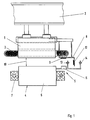
- a stator laminated core 1 is connected in a stationary manner to a guideway 2 built along a predetermined route.
- a long stator winding 3 is inserted in the form of a three-phase winding, which is fed by an inverter with three-phase current of variable amplitude and frequency, as a result of which a progressive current coating wave forms along the long stator motor in a known manner.
- the excitation field of the long-stator synchronous machine is generated by supporting magnets 4, which are connected to a vehicle 5 that moves along the route and is only indicated schematically in FIG. 1 and each consist of a magnetic core 6 and an excitation winding 7.
- the carrying magnets 4 also provide the excitation field of the synchronous machine.
- a stator lamination stack 1 with the associated long stator winding 3 and a plurality of supporting magnets 4 are provided on both sides of the travel path 2.
- the vehicle speed To develop the desired propulsive force, it is necessary for the vehicle speed to be synchronous with the speed of propagation of the current coating wave.
- the maximum propulsion or thrust force results for a given amplitude of the fundamental vibration traveling wave, if an optimal relative position of the vehicle excitation field to the converter shaft is maintained, which in a synchronous three-phase motor ensures compliance with the optimal magnet wheel angle would correspond. This is achieved by regulating the frequency of the inverter, the instantaneous vehicle speed and the relative position of the supporting magnets 4, for example with respect to phase R of the long stator winding 3, being used as reference variables.
- a measuring strip 8 can be attached, which is fixed at an invariable distance from the tooth surface of the stator laminated core 1 and has a fixed association with the long stator winding 3 in the direction of propagation of the current pad shaft.
- a continuous metal coating 9 is applied to this measuring strip 8, which serves as a measuring surface for detecting the supporting gap 10 by means of a sensor 11 which is mounted in a defined position relative to the pole surface of the magnetic core 6.
- a further metallic measuring surface 12 is attached to the measuring bar 8, which has interruptions in the direction of propagation of the current coating wave, which are attached to the long stator winding 3 and form a digital information carrier for the relative pole position and the absolute vehicle position.
- the information stored on the measuring surface 12 is detected, evaluated and processed into signals which indicate the pole position, the absolute vehicle position and the vehicle speed using transmitter and receiver coils 13 and 14 provided on the vehicle 5. These signals are transmitted together with the signals indicating the size of the supporting gap 10, for example by radio, to the lower half of the substation or to a central tail unit.
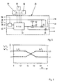
- the long stator winding 3 is activated (FIG. 2) that is currently being driven on by the vehicle 5, for example, moving in the direction of an arrow x .
- the long stator winding 3 as shown only schematically in FIG. 2, is subdivided into a plurality of winding sections 3.11 to 3.19 which follow one another directly in the longitudinal direction of a route and which can be connected to a section cable 17 via an associated switching device 16 each. In Fig. 2, this applies to the winding section 3.14.
- the ends of the section cable 17 are each connected to a lower half 18A or 18B, in which the devices required for feeding the current into the winding sections 3.11 to 3.19, in particular inverters or the like, are installed.
- the substation halves 18A, B can be connected by means of further switching devices 19 to a further route cable 20 or 21 laid along the route if the vehicle 5 is still there has not entered or left the route part defined by the substation halves 18A, B or the section cable 17.
- the long stator winding 3 also consists not only of the winding sections 3.11-3.19, but also of other corresponding winding sections, each of which is connected to the winding sections 3.11-3.19 in a star connection in order to maintain the usual three-phase system with the phases R, S and T. Since these additional winding sections are not required to understand the invention, they have not been shown in FIG. 2 to simplify the illustration.
- the winding sections 3.11-3.19 shown in FIG. 2 are generally used only to drive one, for example the right side of the vehicle 5.
- Corresponding winding sections 3.21-3.29, switching devices 22 and 23, lower part halves 24A, B and section cables 27, 28 and 29 are used to drive the left side of the vehicle in a corresponding manner.
- the winding sections 3.11-3.19, as indicated schematically in FIG. 2 are offset from the winding sections 3.21-3.29 by at least one vehicle length in the x direction in order to enable the so-called alternating step method to be used.
- This consists in that the switching device 16 or 22 is actuated whenever there is a separation point between two winding sections approximately in the middle of the vehicle.
- the corresponding substation halves 18A, 24A and 18B, 24B are each combined to form a substation arranged on the route.
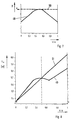
- FIG. 3 shows the equivalent circuit diagram for a winding section 3.11-3.19 or 3.21-3.29 that is just switched on.
- the current required for the nominal operation of the vehicle 5 in this winding section and decisive for the desired nominal speed is denoted by I S and the pole wheel voltage dependent on the instantaneous speed of the vehicle 5 is denoted by U P.
- R S and jX S denote the effective or reactive resistance of the winding section between the respective connection point to the section cable 17 and the star point.
- the substation half 18A feeds the partial current I A and for this purpose must supply a voltage U A which is so much greater than the pole wheel voltage U P than the sum of that occurring through the partial current I A in the associated part of the section cable 17, on the latter Active and reactive resistance R ZA and jX ZA to be attributed to voltage drop U ZA and the voltage drop caused by the active or reactive resistance R S and jX S at the winding section.
- the values R ZA , jX ZA apply in each case to the parts of the feed line or of the section cable 17 which extend from the output of the lower half 18A to the connection point of the respective winding section.
- the resulting voltages are shown in FIG. 4 using the usual vector diagram. The same applies to the voltages and partial currents U B and I B to be applied by the lower half 18B.
- a particularly favorable current distribution is obtained if, when connecting any winding section, for example 3.14, the partial current I A , which is supplied by the closer lower half of the substation, here, for example, 18A, is greater than that partial current I B , which is from the further lower half of the substation, here 18B is delivered.
- the current distribution described is achieved according to the invention with the device shown in FIG. 2.
- This contains a speed controller 31, to which a setpoint for the speed of the vehicle 5 to be achieved or maintained is supplied via a line 32.
- These setpoints are stored in a setpoint memory 33, to which the location signal transmitted by radio 5 from the vehicle 5 is supplied via a line 34, which outputs a setpoint speed value for the winding section in use.
- the controller 31 supplies a desired signal for the current I S which is suitable for achieving the predetermined speed and which is fed to a current distribution block 35, to which the location signals are also fed via the line 34.
- the current distribution block 35 provides at an output 36A a signal which sets the substation half 18A to the voltage U A required to achieve the current I A , and at an output 36B a corresponding signal for the substation half 18B. Further outputs provide corresponding signals for the lower half of the sub-assembly 24A, B.
- the speed controller 31 uses the speed actual signal determined on the vehicle 5, which appears in a line 37, to check that the prescribed target speed is being maintained. The same actual speed signal is also supplied to the current distribution block 35.
- FIG. 5 shows details of the current distribution block 35, which has inputs 38, 39 and 40, respectively, which are connected to the speed controller 31 and the lines 37 and 34 in accordance with FIG.
- the output 36A always emits a signal corresponding to (1- l / d) for the substation half 18A and the output 36B always outputs a signal corresponding to the value l / d for the substation half 18B.
- Corresponding signals can be generated for the substation halves 24A, B.
- a further block 46 (FIGS. 2 and 5), which is also connected to line 34, the data of the entire route are stored. It informs the power distribution block 35, for example, that the lower half 18B, if the vehicle 5 enters the next route section (e.g. corresponding to the section cable 21), it must be connected to the output 36A, because at this moment it is a substation half close to the next winding section, but the output 36B is an output signal related to a distant substation half would deliver.
- the function K f (x) be stored individually for each route section in a table or the like so that the correct signals automatically appear at the outputs 36A, B when the vehicle 5 is changed to another route section.
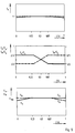
- the current distribution is preferably selected in accordance with FIG. 6.
- dimension d is again the total length of the section cable 17.
- l is the length of the section of section cable 17 used for the infeed, based on the left half of the lower section 18A in FIG. 2, so that d- l is the corresponding length but related to which is the right lower half 18B in FIG. 2.
- the partial current I A supplied by the lower half 18A constantly corresponds to the value 2/3 ⁇ I s as long as this is a nearby substation half and therefore, for example, l / d is equal to or less than 1/3, which would apply in Fig. 2 for the winding sections 3.11-3.13.
- both partial flows I A and I B follow the formula (1-l / d) I S , which would apply in Fig. 2 for the winding sections 3.14-3.16.
- the ratio of the partial stream supplied by the lower half of the substation to the partial stream supplied by the lower half of the substation is 2: 1.
- the proposed current distribution partially nullifies the advantages achieved with regard to the power loss in the section cable 17 and with regard to the reduced maximum voltage in the substation halves 18A, B.
- the partial currents I A , I B to be supplied are limited to the value 2/3 I s .
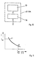
- the overall reduction in power loss V still obtained results from line 48 in FIG. 7, the overall reduction in maximum voltage achieved from line 49 in FIG. 8, in each case based on the symmetrical current distribution I.
- the power loss V is plotted in FIG. 7, and the maximum voltage U A required on the substation half 18A is plotted against l / d in FIG. 8, where l is the distance of the respective winding section from the substation half 18A.
- the smaller maximum voltages for the distant half of the substation for example 5.84 kV instead of 6.05 kV, are used according to the invention to extend the individual winding sections 3.11-3.19 or 3.21-3.29 in the x direction accordingly.
- fewer winding sections and correspondingly fewer switching devices 16 and 22 are required per line section, which leads to considerable cost savings in the case of long lines.
- the lengths of at least those winding sections (for example 3.11-3.13 and 3.17-3.19) which are arranged outside the central region of the route part are optimized in a special way.
- the length of each of these wick - tion sections dimensioned so that the sum of the nominal pole wheel voltage intended for him, the voltage drop that occurs at his active and reactive resistors jX S and R S , and that voltage drop that occurs at the active and reactive resistors R Z and jX Z of occurs from it to the further lying half of the substation of the section cable 17, is constant and independent of the location x of the winding section under consideration.
- the above-mentioned sum is only constant within a winding section if the vehicle speed or the pole wheel voltage U P is also constant. If this is not the case, the above sum applies to the highest pole wheel voltage that occurs in the respective winding section under nominal conditions.
- FIG. 9 shows the different dimensioning of the lengths of the different winding sections 3.11-3.19 purely schematically for a constant operating situation according to the nominal conditions, ie for a journey at constant speed and constant current I S.
- the lengths l W actually to be produced are to be determined by an optimization calculation.
- FIG. 9 shows the associated partial currents I A , I B and partial voltages U A , U B as a function of the distance l / d of the respective winding section from the lower half 18A of the left in FIG. 2.
- the inverters 53 installed in the substation halves 18A, B and 24A, B are normally connected to the section cables 17 and 28 via transformers with predetermined transmission ratios. It is therefore necessary to provide inverters that are adapted to the special requirements of the respective route sections and whose performance is measured according to whether a flat steady-state drive at constant speed, an acceleration drive, a drive on rising terrain or the like should be carried out in the section of the route concerned. Therefore, a large number of different inverters with different outputs have been arranged along the entire route.
- inverters 53 or inverter units consisting of several inverters of the same type in the substation halves arranged along the route, for example 18A (FIG. 10), and instead to select different ratios of the transformers 54.
- the dependence of the current I as a function of the voltage at the output of the transformer 54 is shown schematically in FIG. 11.
- the dependence of the current I on the vehicle speed v is very similar and is therefore not shown separately.
- a small transformation ratio for example at a point C1 enables the generation of high currents at low voltages.
- Such a transmission ratio can be provided, for example, for a line section in which an acceleration run from a standstill or an incline is provided.
- For such acceleration phases mainly low maximum voltages are sufficient because the speed of the vehicle and therefore also the magnet wheel voltage U P is comparatively low. In this phase, an increased maximum current can therefore provide the thrust required for acceleration.
- a transformer 54 with a high transmission ratio for example corresponding to a point C2 in FIG.
- the invention offers the particular advantage that a power reserve is available at least in one of the substation halves 18A, B.
- a power reserve is available at least in one of the substation halves 18A, B.
- that half of the substation that supplies just 1/3 of the current I S into a winding section can theoretically provide a current of 2/3 ⁇ I s are caused according to the other partial flow. This is used according to the invention in order to avoid an excessive drop in the thrust force acting on the vehicle 5 in certain unforeseen malfunctions.
- a whole substation half e.g. 18A
- the location-dependent current distribution described is canceled according to the invention, and the still functional substation halves 18B / 24A / 24B are prompted to simultaneously deliver the maximum possible current, so that in this malfunction the full rated power would still be available.
- This can only be achieved after a certain drop in the vehicle speed, since the substation halves 18B / 24A / 24B work at the voltage limit for these winding sections and can therefore only deliver a higher current than the respective nominal current if the vehicle speed and thus also the magnet wheel voltage U P has decreased accordingly. Nevertheless, the loss of speed is significantly smaller than would be the case if the three still functioning substation halves 18B / 24A / 24B could only supply 50% of the current I S each.
- the invention according to FIG. 5 provides for the current distribution block 35 via line 39 (FIG. 2) the signal which is dependent on the speed of vehicle 5 and via another input 56 that of line 32 supply incoming signal according to the respective speed setpoint. Both signals are fed to a control device 57, for example a comparator or the like, which is connected to a further input of block 41.
- the control device 57 emits, for example, a "0" signal at its output if the actual speed corresponds to the target speed. If, on the other hand, the actual speed is lower or, for example, lower than the target speed by a certain threshold value, then the control device emits, for example, a “1” signal.
- further blocks 58 and 59 could be connected to block 41, in which, on the one hand, the respectively possible fault situations and, on the other hand, the commands to be carried out when one of these fault situations occurs are stored.
- a special fault situation is characterized by an unscheduled stop of the vehicle 5.
- both substation halves 18A, 24A and 18B, 24B are instructed to feed in the same currents I A , I B with an opposite sign compared to normal operation.
- the supply of the braking currents is dependent on the current speed of the vehicle 5, so that the maximum braking currents I.
- all of the substations involved can initially measure the maximum current I.
Landscapes
- Engineering & Computer Science (AREA)
- Power Engineering (AREA)
- Transportation (AREA)
- Mechanical Engineering (AREA)
- Control Of Vehicles With Linear Motors And Vehicles That Are Magnetically Levitated (AREA)
- Control Of Linear Motors (AREA)
- Linear Motors (AREA)
- Electric Propulsion And Braking For Vehicles (AREA)
- Toys (AREA)
- Power Steering Mechanism (AREA)
- Reciprocating, Oscillating Or Vibrating Motors (AREA)
Priority Applications (1)
| Application Number | Priority Date | Filing Date | Title |
|---|---|---|---|
| AT9090108526T ATE104611T1 (de) | 1989-05-25 | 1990-05-07 | Vorrichtung zum betreiben eines magnetfahrzeugs. |
Applications Claiming Priority (2)
| Application Number | Priority Date | Filing Date | Title |
|---|---|---|---|
| DE3917058 | 1989-05-25 | ||
| DE3917058A DE3917058C1 (OSRAM) | 1989-05-25 | 1989-05-25 |
Publications (2)
| Publication Number | Publication Date |
|---|---|
| EP0399268A1 EP0399268A1 (de) | 1990-11-28 |
| EP0399268B1 true EP0399268B1 (de) | 1994-04-20 |
Family
ID=6381384
Family Applications (1)
| Application Number | Title | Priority Date | Filing Date |
|---|---|---|---|
| EP90108526A Expired - Lifetime EP0399268B1 (de) | 1989-05-25 | 1990-05-07 | Vorrichtung zum Betreiben eines Magnetfahrzeugs |
Country Status (8)
| Country | Link |
|---|---|
| US (1) | US5053654A (OSRAM) |
| EP (1) | EP0399268B1 (OSRAM) |
| JP (1) | JP2739606B2 (OSRAM) |
| AT (1) | ATE104611T1 (OSRAM) |
| CA (1) | CA2016890C (OSRAM) |
| DD (1) | DD294665A5 (OSRAM) |
| DE (2) | DE3917058C1 (OSRAM) |
| RU (1) | RU2075405C1 (OSRAM) |
Families Citing this family (40)
| Publication number | Priority date | Publication date | Assignee | Title |
|---|---|---|---|---|
| US5569987A (en) * | 1994-03-04 | 1996-10-29 | Siemens Aktiengesellschaft | Power supply system for a long-stator drive for a magnetic levitation train |
| DE4441757B4 (de) * | 1994-03-07 | 2009-04-09 | Siemens Ag | Verfahren zur Übermittlung von Daten von einem beweglichen Teil eines Langstatorantriebs zu stationären Einrichtungen des Langstatorantriebs |
| DE19748911A1 (de) * | 1997-11-05 | 1999-05-06 | Intrasys Gmbh | Linearantriebssystem |
| US7262523B1 (en) * | 1998-02-26 | 2007-08-28 | Anorad Corporation | Wireless encoder |
| DE19922441A1 (de) * | 1999-05-07 | 2000-11-09 | Transrapid International Gmbh | Verfahren und Vorrichtung zum Betreiben eines Magnetfahrzeugs |
| ATE348728T1 (de) | 2002-04-10 | 2007-01-15 | Transrapid Int Gmbh & Co Kg | Vorrichtung zum betreiben eines magnetfahrzeugs |
| DE102004056438A1 (de) * | 2004-03-15 | 2005-10-06 | Thyssenkrupp Transrapid Gmbh | Führmagnetsystem und damit ausgerüstetes Magnetschwebefahrzeug |
| DE102004013692A1 (de) | 2004-03-18 | 2005-10-06 | Thyssenkrupp Transrapid Gmbh | Verfahren bei einem Magnetschwebefahrzeug zur Regelung von Tragspalten und Magnetschwebefahrzeug mit nach diesem Verfahren arbeitenden Regelkreisen |
| DE102004013994A1 (de) | 2004-03-19 | 2005-10-06 | Thyssenkrupp Transrapid Gmbh | Magnetschwebebahn mit einer Wirbelstrombremse |
| DE102004015096A1 (de) * | 2004-03-25 | 2005-10-13 | Thyssenkrupp Transrapid Gmbh | Vorrichtung zum Verbinden des Mantels einer elektrischen Wicklung mit einer Erdungsleitung und damit ausgerüstete Magnetschwebebahn |
| DE102004018311B4 (de) | 2004-04-13 | 2015-09-17 | Thyssenkrupp Transrapid Gmbh | Vorrichtung zur automatischen Steuerung eines spurgebundenen Fahrzeugs |
| DE102004025514A1 (de) | 2004-04-13 | 2005-11-03 | Thyssenkrupp Transrapid Gmbh | Vorrichtung zur Steuerung einer am Fahrweg eines spurgebundenen Fahrzeugs angeordneten Bahnsteigtür |
| DE102004054918A1 (de) * | 2004-11-10 | 2006-05-11 | Transrapid International Gmbh & Co. Kg | Vorrichtung mit wenigstens einem Langstator-Linearantrieb zum Betreiben von Magnetschwebefahrzeugen |
| DE102004054919A1 (de) * | 2004-11-10 | 2006-05-11 | Transrapid International Gmbh & Co. Kg | Verfahren und Vorrichtung zum Betreiben eines Magnetschwebefahrzeugs |
| DE102005024309B4 (de) * | 2005-05-20 | 2010-12-30 | Siemens Ag | Einschaltverriegelung für einen Antrieb eines sich längs einer Fahrbahn bewegenden Fahrzeugs, insbesondere einer Magnetschwebebahn, sowie Antrieb mit einer entsprechenden Einschaltverriegelung |
| WO2007137536A1 (de) * | 2006-05-31 | 2007-12-06 | Siemens Aktiengesellschaft | Anordnung mit einer vielzahl an elektrischen schaltern, insbesondere für eine magnetschwebebahnstrecke |
| WO2007137541A1 (de) * | 2006-05-31 | 2007-12-06 | Siemens Aktiengesellschaft | Transportable schaltstelle für ein magnetschwebebahnsystem |
| US8224509B2 (en) * | 2006-08-25 | 2012-07-17 | General Atomics | Linear synchronous motor with phase control |
| RU2320074C1 (ru) * | 2006-11-03 | 2008-03-20 | Государственное Научное Учреждение "Объединенный Институт Машиностроения Национальной Академии Наук Беларуси" | Электромагнитный линейный привод |
| DE102006053583B4 (de) * | 2006-11-10 | 2015-07-16 | Thyssenkrupp Transrapid Gmbh | Magnetschwebefahrzeug |
| DE102006056335A1 (de) | 2006-11-27 | 2008-07-03 | Thyssenkrupp Transrapid Gmbh | Magnetschwebefahrzeug mit wenigstens einem Magnetsystem |
| DE102007004919B4 (de) * | 2007-01-26 | 2018-09-27 | Siemens Aktiengesellschaft | Verfahren und Einrichtung zur Antriebssteuerung eines Magnetschwebefahrzeugs auf einer Magnetschwebebahnstrecke |
| DE102007025793A1 (de) | 2007-06-01 | 2008-12-04 | Thyssenkrupp Transrapid Gmbh | Fahrzeug mit einer Wirbelstrombremse für ein spurgebundenes Verkehrssystem und damit betriebenes Verkehrssystem, insbesondere Magentschwebebahn |
| US8616134B2 (en) | 2009-01-23 | 2013-12-31 | Magnemotion, Inc. | Transport system powered by short block linear synchronous motors |
| US9032880B2 (en) | 2009-01-23 | 2015-05-19 | Magnemotion, Inc. | Transport system powered by short block linear synchronous motors and switching mechanism |
| US8109353B2 (en) * | 2009-04-02 | 2012-02-07 | General Atomics | Transport system incorporating linear motor charged electric vehicle |
| DE102009049225A1 (de) | 2009-10-09 | 2011-05-05 | Thyssenkrupp Transrapid Gmbh | Muffe zur Verbindung der Enden von Wicklungen eines Langstator-Linearmotors und damit ausgerüsteter Langstator |
| GB2476318A (en) * | 2009-12-21 | 2011-06-22 | Bombardier Transp Gmbh | Laying electrical conductors along a track for a vehicle |
| DE102010026586A1 (de) | 2010-07-08 | 2012-01-12 | Roland Lipp | Fahrbahn für eine Magnetschwebebahn |
| DE102010048819A1 (de) | 2010-10-20 | 2012-04-26 | Roland Lipp | Hochgeschwindigkeits-Fernverkehrssystem zum Transport von Personen und/oder Lasten |
| WO2015042409A1 (en) | 2013-09-21 | 2015-03-26 | Magnemotion, Inc. | Linear motor transport for packaging and other uses |
| CN107466444B (zh) | 2015-02-08 | 2019-05-17 | 超级高铁技术公司 | 动态直线定子段控制 |
| WO2016126502A1 (en) | 2015-02-08 | 2016-08-11 | Hyperloop Technologies, Inc | Power supply system and method for a movable vehicle within a structure |
| US10958147B2 (en) | 2015-02-08 | 2021-03-23 | Hyperloop Technologies, Inc. | Continuous winding for electric motors |
| US10897216B2 (en) | 2015-10-29 | 2021-01-19 | Hyperloop Technologies, Inc. | Variable frequency drive system |
| US10533289B2 (en) | 2016-03-28 | 2020-01-14 | Hyperloop Technologies, Inc. | Metamaterial null flux magnet bearing system |
| CN106740248B (zh) * | 2017-01-24 | 2019-01-22 | 株洲中车时代电气股份有限公司 | 一种高速磁悬浮交通系统及其列车的牵引供电系统 |
| CN107225996B (zh) | 2017-05-31 | 2019-08-20 | 中车株洲电力机车有限公司 | 一种磁悬浮列车的供电系统 |
| US10608469B2 (en) * | 2017-09-28 | 2020-03-31 | Rockwell Automation Technologies, Inc. | Method and apparatus for power transfer to an independent moving cart during travel along a track |
| CN113271050B (zh) * | 2021-06-09 | 2023-04-28 | 同济大学 | 一种长定子双馈直线电机准同步供电控制方法 |
Family Cites Families (13)
| Publication number | Priority date | Publication date | Assignee | Title |
|---|---|---|---|---|
| US4068152A (en) * | 1972-03-08 | 1978-01-10 | Hitachi, Ltd. | Power supply system for a linear motor |
| NL7315725A (OSRAM) * | 1972-12-30 | 1974-07-02 | ||
| GB1449469A (en) * | 1973-06-01 | 1976-09-15 | Lamb C St J | Linear electric motor systems |
| DE2341761C3 (de) * | 1973-08-17 | 1978-04-13 | Siemens Ag, 1000 Berlin Und 8000 Muenchen | Schaltungsanordnung zum Betrieb eines fahrweggebundenen Triebfahrzeuges mit einem synchronen Linearmotor |
| US3914669A (en) * | 1973-11-13 | 1975-10-21 | Siemens Ag | System for attenuating vertical oscillations of a suspended track bound propulsion vehicle |
| DE2425940A1 (de) * | 1974-05-30 | 1975-12-11 | City Bahn Gmbh | Antrieb und steuerung einer automatischen bahn |
| US4061089A (en) * | 1975-09-02 | 1977-12-06 | Elbert Morgan Sawyer | Personal rapid transit system |
| DE2932764A1 (de) * | 1979-08-13 | 1981-03-26 | Siemens AG, 1000 Berlin und 8000 München | Anordnung zur stromversorgung der wanderfeldwicklung eines synchronen linearmotors |
| DE3110339C2 (de) * | 1981-03-17 | 1984-09-27 | Thyssen Industrie Ag, 4300 Essen | Verfahren zum Herstellen eines Blechpakets für einen Langstator-Linearmotor |
| DE3382199D1 (de) * | 1982-02-10 | 1991-04-18 | Thyssen Industrie | Vorrichtung zur inkrementalen erfassung der fahrzeuglage eines magnetschwebefahrzeuges. |
| DE3303961A1 (de) * | 1982-02-10 | 1983-08-18 | Thyssen Industrie Ag, 4300 Essen | Vorrichtung zur inkrementalen erfassung der fahrzeuglage eines magnetschwebefahrzeuges |
| JPH0667050B2 (ja) * | 1983-08-31 | 1994-08-24 | 株式会社日立製作所 | リニアモータ式鉄道の給電装置 |
| DE3404061C1 (de) * | 1984-02-06 | 1985-09-05 | Thyssen Industrie Ag, 4300 Essen | Verfahren zur Iagegenauen Befestigung von Ausruestungsteilen an vorgegebenen Anschlussorten an der Tragkonstruktion von Fahrwegen |
-
1989
- 1989-05-25 DE DE3917058A patent/DE3917058C1/de not_active Expired - Lifetime
-
1990
- 1990-05-07 DE DE59005405T patent/DE59005405D1/de not_active Expired - Fee Related
- 1990-05-07 AT AT9090108526T patent/ATE104611T1/de not_active IP Right Cessation
- 1990-05-07 EP EP90108526A patent/EP0399268B1/de not_active Expired - Lifetime
- 1990-05-16 CA CA002016890A patent/CA2016890C/en not_active Expired - Lifetime
- 1990-05-21 US US07/527,123 patent/US5053654A/en not_active Expired - Lifetime
- 1990-05-23 DD DD90340959A patent/DD294665A5/de not_active IP Right Cessation
- 1990-05-23 JP JP2133681A patent/JP2739606B2/ja not_active Expired - Fee Related
- 1990-05-24 RU SU904743929A patent/RU2075405C1/ru not_active IP Right Cessation
Also Published As
| Publication number | Publication date |
|---|---|
| JP2739606B2 (ja) | 1998-04-15 |
| ATE104611T1 (de) | 1994-05-15 |
| RU2075405C1 (ru) | 1997-03-20 |
| JPH0370404A (ja) | 1991-03-26 |
| CA2016890C (en) | 1998-06-23 |
| DE59005405D1 (de) | 1994-05-26 |
| DD294665A5 (de) | 1991-10-10 |
| US5053654A (en) | 1991-10-01 |
| DE3917058C1 (OSRAM) | 1990-11-08 |
| EP0399268A1 (de) | 1990-11-28 |
| CA2016890A1 (en) | 1990-11-25 |
Similar Documents
| Publication | Publication Date | Title |
|---|---|---|
| EP0399268B1 (de) | Vorrichtung zum Betreiben eines Magnetfahrzeugs | |
| EP1352778B1 (de) | Vorrichtung zum Betreiben eines Magnetfahrzeugs | |
| EP1050427B1 (de) | Verfahren und Vorrichtung zum Betreiben eines Magnetfahrzeugs | |
| EP3581428B1 (de) | Kurzschlussbremsung eines llm | |
| EP0904213B1 (de) | Abschnittswechselverfahren für bahnsysteme mit langstator-linearmotor | |
| DE2932549C2 (de) | Stromversorgungssystem für Langstator-Linearmotor | |
| DE102007003118A1 (de) | Magnetschwebebahn und Verfahren zu deren Betrieb | |
| DE3011980A1 (de) | Speisesystem fuer linearmotorbloecketransportsystem | |
| EP1657107A1 (de) | Vorrichtung mit wenigstens einem Langstator-Linearantrieb zum Betreiben von Magnetschwebefahrzeugen | |
| DE102004056438A1 (de) | Führmagnetsystem und damit ausgerüstetes Magnetschwebefahrzeug | |
| EP1651464A1 (de) | Berührungslose energieversorgung für bewegte verbraucher | |
| DE102004054919A1 (de) | Verfahren und Vorrichtung zum Betreiben eines Magnetschwebefahrzeugs | |
| DE3331953A1 (de) | Elektromagnetischer linearantrieb | |
| DE2541599A1 (de) | Integrierte magnetfahrtechnik fuer den nahverkehr | |
| WO2001096139A2 (de) | Verfahren und anordnung zum berührungslosen transport eines fahrzeuges auf einer schienenanordnung | |
| DE10227253A1 (de) | Vorrichtung zum Betreiben eines Magnetfahrzeugs | |
| DE3043004C2 (de) | Elektrischer Einzelradantrieb bei mehrachsigen Fahrzeugen | |
| EP0877466B1 (de) | Antriebsmittel für eine Linearbewegung insbesondere kontinuierliche Linearbewegung und Langstator-Linearmotor | |
| DE2316679C3 (OSRAM) | ||
| DE3808941C2 (de) | Verfahren zum unterbrechungsfreien und stromlosen Abschnittswechsel bei einem Langstator-Linearmotor | |
| DE2925867A1 (de) | Magnetanordnung fuer trag-, fuehr- und vortriebsbildung bei magnet-schwebefahrzeugen | |
| DE1413569C (de) | Kontaktlos arbeitende Befehlsgeber steuerung fur elektrische Triebfahrzeuge | |
| DE3410066A1 (de) | Transport- und positioniereinrichtung zum abrichten von walzgut | |
| DE2363068C3 (de) | Verfahren zur Steuerung eines über einen Umrichter gespeisten einseitigen asynchronen Linearmotors | |
| DE2444679C3 (de) | Schaltungsanordnung für ein fahrweggebundenes Triebfahrzeug, das mit einem synchronen Linearmotor ausgerüstet ist |
Legal Events
| Date | Code | Title | Description |
|---|---|---|---|
| PUAI | Public reference made under article 153(3) epc to a published international application that has entered the european phase |
Free format text: ORIGINAL CODE: 0009012 |
|
| AK | Designated contracting states |
Kind code of ref document: A1 Designated state(s): AT CH DE FR GB IT LI SE |
|
| 17P | Request for examination filed |
Effective date: 19901222 |
|
| 17Q | First examination report despatched |
Effective date: 19930908 |
|
| GRAA | (expected) grant |
Free format text: ORIGINAL CODE: 0009210 |
|
| AK | Designated contracting states |
Kind code of ref document: B1 Designated state(s): AT CH DE FR GB IT LI SE |
|
| REF | Corresponds to: |
Ref document number: 104611 Country of ref document: AT Date of ref document: 19940515 Kind code of ref document: T |
|
| REF | Corresponds to: |
Ref document number: 59005405 Country of ref document: DE Date of ref document: 19940526 |
|
| GBT | Gb: translation of ep patent filed (gb section 77(6)(a)/1977) |
Effective date: 19940504 |
|
| ITF | It: translation for a ep patent filed | ||
| ET | Fr: translation filed | ||
| EAL | Se: european patent in force in sweden |
Ref document number: 90108526.6 |
|
| PLBE | No opposition filed within time limit |
Free format text: ORIGINAL CODE: 0009261 |
|
| 26N | No opposition filed | ||
| REG | Reference to a national code |
Ref country code: GB Ref legal event code: IF02 |
|
| PGFP | Annual fee paid to national office [announced via postgrant information from national office to epo] |
Ref country code: SE Payment date: 20060512 Year of fee payment: 17 |
|
| PGFP | Annual fee paid to national office [announced via postgrant information from national office to epo] |
Ref country code: AT Payment date: 20060515 Year of fee payment: 17 Ref country code: CH Payment date: 20060515 Year of fee payment: 17 |
|
| PGFP | Annual fee paid to national office [announced via postgrant information from national office to epo] |
Ref country code: FR Payment date: 20060519 Year of fee payment: 17 |
|
| PGFP | Annual fee paid to national office [announced via postgrant information from national office to epo] |
Ref country code: IT Payment date: 20060531 Year of fee payment: 17 |
|
| REG | Reference to a national code |
Ref country code: CH Ref legal event code: PFA Owner name: THYSSEN INDUSTRIE AG Free format text: THYSSEN INDUSTRIE AG#AM THYSSENHAUS 1#D-45128 ESSEN (DE) -TRANSFER TO- THYSSEN INDUSTRIE AG#AM THYSSENHAUS 1#D-45128 ESSEN (DE) |
|
| EUG | Se: european patent has lapsed | ||
| REG | Reference to a national code |
Ref country code: CH Ref legal event code: PL |
|
| PG25 | Lapsed in a contracting state [announced via postgrant information from national office to epo] |
Ref country code: CH Free format text: LAPSE BECAUSE OF NON-PAYMENT OF DUE FEES Effective date: 20070531 Ref country code: LI Free format text: LAPSE BECAUSE OF NON-PAYMENT OF DUE FEES Effective date: 20070531 Ref country code: AT Free format text: LAPSE BECAUSE OF NON-PAYMENT OF DUE FEES Effective date: 20070507 |
|
| REG | Reference to a national code |
Ref country code: FR Ref legal event code: ST Effective date: 20080131 |
|
| PG25 | Lapsed in a contracting state [announced via postgrant information from national office to epo] |
Ref country code: SE Free format text: LAPSE BECAUSE OF NON-PAYMENT OF DUE FEES Effective date: 20070508 |
|
| PG25 | Lapsed in a contracting state [announced via postgrant information from national office to epo] |
Ref country code: FR Free format text: LAPSE BECAUSE OF NON-PAYMENT OF DUE FEES Effective date: 20070531 |
|
| PGFP | Annual fee paid to national office [announced via postgrant information from national office to epo] |
Ref country code: DE Payment date: 20080523 Year of fee payment: 19 |
|
| PGFP | Annual fee paid to national office [announced via postgrant information from national office to epo] |
Ref country code: GB Payment date: 20080522 Year of fee payment: 19 |
|
| PG25 | Lapsed in a contracting state [announced via postgrant information from national office to epo] |
Ref country code: IT Free format text: LAPSE BECAUSE OF NON-PAYMENT OF DUE FEES Effective date: 20070507 |
|
| GBPC | Gb: european patent ceased through non-payment of renewal fee |
Effective date: 20090507 |
|
| PG25 | Lapsed in a contracting state [announced via postgrant information from national office to epo] |
Ref country code: GB Free format text: LAPSE BECAUSE OF NON-PAYMENT OF DUE FEES Effective date: 20090507 |
|
| PG25 | Lapsed in a contracting state [announced via postgrant information from national office to epo] |
Ref country code: DE Free format text: LAPSE BECAUSE OF NON-PAYMENT OF DUE FEES Effective date: 20091201 |