EP0396898B1 - Kolben für Kolbenmaschinen - Google Patents
Kolben für Kolbenmaschinen Download PDFInfo
- Publication number
- EP0396898B1 EP0396898B1 EP90106187A EP90106187A EP0396898B1 EP 0396898 B1 EP0396898 B1 EP 0396898B1 EP 90106187 A EP90106187 A EP 90106187A EP 90106187 A EP90106187 A EP 90106187A EP 0396898 B1 EP0396898 B1 EP 0396898B1
- Authority
- EP
- European Patent Office
- Prior art keywords
- piston
- filler piece
- filler
- spring
- cavity
- Prior art date
- Legal status (The legal status is an assumption and is not a legal conclusion. Google has not performed a legal analysis and makes no representation as to the accuracy of the status listed.)
- Expired - Lifetime
Links
Images
Classifications
-
- F—MECHANICAL ENGINEERING; LIGHTING; HEATING; WEAPONS; BLASTING
- F04—POSITIVE - DISPLACEMENT MACHINES FOR LIQUIDS; PUMPS FOR LIQUIDS OR ELASTIC FLUIDS
- F04B—POSITIVE-DISPLACEMENT MACHINES FOR LIQUIDS; PUMPS
- F04B1/00—Multi-cylinder machines or pumps characterised by number or arrangement of cylinders
- F04B1/12—Multi-cylinder machines or pumps characterised by number or arrangement of cylinders having cylinder axes coaxial with, or parallel or inclined to, main shaft axis
- F04B1/122—Details or component parts, e.g. valves, sealings or lubrication means
- F04B1/124—Pistons
-
- F—MECHANICAL ENGINEERING; LIGHTING; HEATING; WEAPONS; BLASTING
- F05—INDEXING SCHEMES RELATING TO ENGINES OR PUMPS IN VARIOUS SUBCLASSES OF CLASSES F01-F04
- F05C—INDEXING SCHEME RELATING TO MATERIALS, MATERIAL PROPERTIES OR MATERIAL CHARACTERISTICS FOR MACHINES, ENGINES OR PUMPS OTHER THAN NON-POSITIVE-DISPLACEMENT MACHINES OR ENGINES
- F05C2201/00—Metals
- F05C2201/04—Heavy metals
- F05C2201/0433—Iron group; Ferrous alloys, e.g. steel
- F05C2201/0448—Steel
- F05C2201/0457—Cemented steel
-
- F—MECHANICAL ENGINEERING; LIGHTING; HEATING; WEAPONS; BLASTING
- F05—INDEXING SCHEMES RELATING TO ENGINES OR PUMPS IN VARIOUS SUBCLASSES OF CLASSES F01-F04
- F05C—INDEXING SCHEME RELATING TO MATERIALS, MATERIAL PROPERTIES OR MATERIAL CHARACTERISTICS FOR MACHINES, ENGINES OR PUMPS OTHER THAN NON-POSITIVE-DISPLACEMENT MACHINES OR ENGINES
- F05C2251/00—Material properties
- F05C2251/04—Thermal properties
- F05C2251/042—Expansivity
-
- F—MECHANICAL ENGINEERING; LIGHTING; HEATING; WEAPONS; BLASTING
- F05—INDEXING SCHEMES RELATING TO ENGINES OR PUMPS IN VARIOUS SUBCLASSES OF CLASSES F01-F04
- F05C—INDEXING SCHEME RELATING TO MATERIALS, MATERIAL PROPERTIES OR MATERIAL CHARACTERISTICS FOR MACHINES, ENGINES OR PUMPS OTHER THAN NON-POSITIVE-DISPLACEMENT MACHINES OR ENGINES
- F05C2253/00—Other material characteristics; Treatment of material
- F05C2253/12—Coating
-
- Y—GENERAL TAGGING OF NEW TECHNOLOGICAL DEVELOPMENTS; GENERAL TAGGING OF CROSS-SECTIONAL TECHNOLOGIES SPANNING OVER SEVERAL SECTIONS OF THE IPC; TECHNICAL SUBJECTS COVERED BY FORMER USPC CROSS-REFERENCE ART COLLECTIONS [XRACs] AND DIGESTS
- Y10—TECHNICAL SUBJECTS COVERED BY FORMER USPC
- Y10T—TECHNICAL SUBJECTS COVERED BY FORMER US CLASSIFICATION
- Y10T29/00—Metal working
- Y10T29/49—Method of mechanical manufacture
- Y10T29/49229—Prime mover or fluid pump making
- Y10T29/49249—Piston making
-
- Y—GENERAL TAGGING OF NEW TECHNOLOGICAL DEVELOPMENTS; GENERAL TAGGING OF CROSS-SECTIONAL TECHNOLOGIES SPANNING OVER SEVERAL SECTIONS OF THE IPC; TECHNICAL SUBJECTS COVERED BY FORMER USPC CROSS-REFERENCE ART COLLECTIONS [XRACs] AND DIGESTS
- Y10—TECHNICAL SUBJECTS COVERED BY FORMER USPC
- Y10T—TECHNICAL SUBJECTS COVERED BY FORMER US CLASSIFICATION
- Y10T29/00—Metal working
- Y10T29/49—Method of mechanical manufacture
- Y10T29/49826—Assembling or joining
- Y10T29/49908—Joining by deforming
- Y10T29/49915—Overedge assembling of seated part
- Y10T29/49917—Overedge assembling of seated part by necking in cup or tube wall
- Y10T29/49918—At cup or tube end
Definitions
- the invention relates to a piston according to the preamble of claim 1.
- a piston of this type is described and shown in DD-PS 73 453.
- the filler is tapered in a stepped manner towards its inner end, the tapered section carrying an external thread with which the filler is screwed into a corresponding internal thread in the wall of the cavity of the hollow body and is thus fastened.
- An axially parallel pin which is arranged at the free end of the hollow body and of the filler in a position in which it penetrates the parting line between the filler and the hollow body, serves as an anti-twist device.
- a radial spring washer inserted at the free end of the cavity in an annular groove and a disc spring inserted between the latter and the filler piece are dimensioned so large that their peripheral edge extends in front of the facing end of the locking pin. The locking pin can therefore not move axially out of its receiving hole.
- This known embodiment is very complex and expensive, because not only an external and internal thread and the receiving hole for the locking pin are to be made, but also the mounting of the locking pin must be carried out.
- the axial securing of the filler is inadequate because, due to the different materials and thermal expansion coefficients of the hollow body and the filler with regard to temperature fluctuations to be expected during operation of the piston machine, a loosening in the thread occurs, although the filler is axially secured against unscrewing by the locking pin.
- the invention has for its object to design a piston of the type mentioned in such a way that loosening of the filler is prevented while ensuring an inexpensive manufacture.
- the invention is based on the finding that loosening of the filler in the cavity is prevented in principle only by a spring element which counteracts the inertial forces of the filler in its exertion of force and thus compensates for changes in length due to the influence of temperature.
- the filler is biased only by the biasing force of the spring via the securing element against the bottom of the cavity and thus secured and fastened.
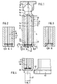
- the essential parts of the piston are the cylindrical hollow body 3 forming the piston shaft 2, a filler piece 5 made of a lighter material than the material of the hollow body 3 and arranged in the cavity 4 of the hollow body 3, and a plate spring 6 which is located between the filler piece 5 and a securing element 8 is inserted at the outer end of the cavity 4 or its opening 9 at the free end 7 of the piston 1.
- the cavity 4 is formed by a blind bore 11, the bottom 12 of which, as shown in FIG. 1, can be conical or also perpendicular to the central axis 13 of the piston 1.
- the filler 5 is adapted in the region of its inner end to the shape of the base 12, the inner end face 14 resting on the base 12 of the blind bore 11.
- the length 1 of the filler 5 is dimensioned somewhat less than the length L of the piston skirt 2, so that its free end 7 projects beyond the outer end of the filler 5.
- a piston head 16 carried by it is provided, which is pivotally received on all sides in a spherical recess 17 of a known slide shoe 18.
- An axial lubrication channel 19 extends longitudinally through the piston 1 to the slide shoe 18.
- the filler 5 is received in the blind bore 11 with as little radial play as possible. It exists in the present Embodiment made of an aluminum alloy.
- the filler 5 can be poured in or preferably inserted or inserted. It is recommended that the filler 5 be pressed in, which ensures a radial play-free reception even if, due to different dimensions and / or expansion coefficients, the hollow body 3 expands radially slightly more than the filler 5.
- the filler 5 is held in the blind bore 11 without rattling.
- the distance a between the outer end face 24 of the filler 5 and the securing element 8 is dimensioned slightly larger than the thickness d of the plate spring 6, so that in the installed state there is a play S between the outer end face 24 of the filler 5 and the peripheral edge 22 of the plate spring 6 exists.
- the movement play S is preferably dimensioned so large that with an axial length extension of the filler 5, which is greater than that of the hollow body 3, the filler 5 can expand relative to the hollow body 3 within the movement play S. Despite this movement game S, the filler 5 is due to The clamping force of the plate spring 6 is held in the blind bore 11 without rattling.
- the plate spring 6 has a central round hole 25, the diameter of which preferably corresponds to the diameter of the lubrication bore 19.
- the spring 6 represents an advantageous protection for the outer end or the outer end face 24 of the filler 5, in particular a protection against cavitation during the operation of the piston 1.
- Such protection can be provided for a filler 5 made of aluminum can be further improved by hard coating, as a result of which the outer end face 24 or in particular the inner peripheral edge and the wall of the lubrication bore 19 of the filler 5 become harder or more wear-resistant.
- the securing element 8 is formed by a flange 31 of the edge 32 of the hollow body 3 projecting beyond the outer end of the filler 5, the flange 31 engaging behind the outer circumference of the plate spring 6.
- the filler 5 by means of a screw part 33, which is screwed with an external thread into an internal thread of the blind bore 11 or a step recess at the free end of the cylindrical hollow body 3 and thereby preferably closes with the free end face of the piston 1 (Fig . 2). If a lubrication bore 19 is present in the piston 1, the screw part 33 also has a central bore 34 with a corresponding cross section.
- the screw part 33 on which at least one externally accessible, not shown attack element, for example two diametrically opposite blind holes, is provided, can be screwed into the hollow body 3 to such an extent that the filler piece 5 is clamped against the base 12.
- the screw part 33 can rest against a shoulder or the like of the blind bore 11 and be clamped by a tightening, or it can be secured in this position in some other way , for example by means known for this purpose, such as Loctite. It is advisable to design the screw part 33 in the form of an inner nut with a self-locking thread.
- the securing element 8 is formed by a radial spring washer 35, which is inserted into a groove 36 in the wall of the blind bore 11.
- the disc springs 6 are of the same design in all of the above-described exemplary embodiments.
- the diameter d 1 of the bolt 41 is to be dimensioned slightly smaller than the opening 9 delimited by the flange 31 at the free end of the piston 1 or piston skirt 2.
- the piston 1 is made in one piece and consists of steel, in particular alloy steel.
Landscapes
- Engineering & Computer Science (AREA)
- Mechanical Engineering (AREA)
- General Engineering & Computer Science (AREA)
- Pistons, Piston Rings, And Cylinders (AREA)
- Fluid-Damping Devices (AREA)
Applications Claiming Priority (2)
| Application Number | Priority Date | Filing Date | Title |
|---|---|---|---|
| DE3912213A DE3912213C1 (enExample) | 1989-04-13 | 1989-04-13 | |
| DE3912213 | 1989-04-13 |
Publications (2)
| Publication Number | Publication Date |
|---|---|
| EP0396898A1 EP0396898A1 (de) | 1990-11-14 |
| EP0396898B1 true EP0396898B1 (de) | 1993-09-01 |
Family
ID=6378640
Family Applications (1)
| Application Number | Title | Priority Date | Filing Date |
|---|---|---|---|
| EP90106187A Expired - Lifetime EP0396898B1 (de) | 1989-04-13 | 1990-03-30 | Kolben für Kolbenmaschinen |
Country Status (3)
| Country | Link |
|---|---|
| US (1) | US5007332A (enExample) |
| EP (1) | EP0396898B1 (enExample) |
| DE (2) | DE3912213C1 (enExample) |
Families Citing this family (16)
| Publication number | Priority date | Publication date | Assignee | Title |
|---|---|---|---|---|
| DE4108786C2 (de) * | 1991-03-18 | 1995-01-05 | Hydromatik Gmbh | Leichtkolben für hydrostatische Axial- und Radialkolbenmaschinen |
| US5642654A (en) * | 1994-09-01 | 1997-07-01 | Sundstrand Corporation | Piston and method of manufacturing the same |
| US5568762A (en) * | 1995-04-12 | 1996-10-29 | Caterpillar Inc. | Stabilizing device for variable displacement axial piston pumps |
| US6250206B1 (en) * | 1999-02-10 | 2001-06-26 | Sauer-Danfoss Inc. | Hydraulic piston filling |
| FR2794507B1 (fr) * | 1999-06-04 | 2001-07-13 | Valeo | Piston et dispositif de commande hydraulique d'un embrayage de vehicule automobile comportant un tel piston |
| DE19934218C2 (de) * | 1999-07-21 | 2003-03-20 | Brueninghaus Hydromatik Gmbh | Verfahren zum Herstellen einer Kugelgelenkverbindung zwischen einem Gleitschuh und einem Kolben und Axialkolbenmaschine mit einer Kugelgelenkverbindung |
| DE19938046A1 (de) * | 1999-08-12 | 2001-03-08 | Brueninghaus Hydromatik Gmbh | Hohlkolben für eine Kolbenmaschine und Verfahren zum Herstellen eines Hohlkolbens |
| US6318242B1 (en) | 1999-10-26 | 2001-11-20 | Sauer-Danfoss Inc. | Filled hydraulic piston and method of making the same |
| US6293185B1 (en) | 2000-02-28 | 2001-09-25 | Sauer-Danfoss Inc. | Piston for a hydrostatic cylinder block |
| US6431051B1 (en) | 2000-03-31 | 2002-08-13 | Sauer-Danfoss Inc. | Closed cavity hydraulic piston and method of making the same |
| US6338293B1 (en) | 2000-06-30 | 2002-01-15 | Sauer-Danfoss Inc. | Reduced oil volume piston assembly for a hydrostatic unit |
| US6314864B1 (en) | 2000-07-20 | 2001-11-13 | Sauer-Danfoss Inc. | Closed cavity piston for hydrostatic units |
| US6588321B1 (en) | 2000-11-27 | 2003-07-08 | Sauer-Danfoss Inc. | Closed cavity piston and method of making the same |
| DE102009056903A1 (de) * | 2009-12-03 | 2011-06-09 | Danfoss A/S | Hydraulische Kolbenmaschine, insbesondere wasserhydraulische Maschine |
| DE102019130844A1 (de) | 2019-11-15 | 2021-05-20 | Danfoss A/S | Hydraulische Kolbenmaschine |
| DE102019130843A1 (de) * | 2019-11-15 | 2021-05-20 | Danfoss A/S | Kolben einer hydraulischen Kolbenmaschine und hydraulische Kolbenmaschine |
Family Cites Families (24)
| Publication number | Priority date | Publication date | Assignee | Title |
|---|---|---|---|---|
| DD73453A (enExample) * | ||||
| US2541250A (en) * | 1947-06-19 | 1951-02-13 | Girling Ltd | Fluid-tight closure for a cylinder or other container |
| US2980077A (en) * | 1959-03-17 | 1961-04-18 | English Electric Co Ltd | Hydraulic devices |
| US3178907A (en) * | 1963-01-21 | 1965-04-20 | Dana Corp | Universal joint |
| DE1200609B (de) * | 1963-07-31 | 1965-09-09 | Mahle Kg | Mehrteiliger Brennkraftmaschinenkolben |
| US3187644A (en) * | 1963-08-19 | 1965-06-08 | Sundstrand Corp | Hydraulic pump or motor device pistons |
| US3319575A (en) * | 1965-06-14 | 1967-05-16 | Sundstrand Corp | Piston |
| DE1653388B2 (de) * | 1967-10-21 | 1975-04-24 | Robert Bosch Gmbh, 7000 Stuttgart | Hydraulische Arbeitsmaschine |
| US3633467A (en) * | 1968-12-28 | 1972-01-11 | Komatsu Mfg Co Ltd | Hydraulic pump or motor device plungers |
| DE1936778B2 (de) * | 1969-07-19 | 1973-02-15 | Rheinmetall GmbH, 4000 Dusseldorf | Vorrichtung zum vereinzeln des jeweils untersten kartonzuschnitts aus einem stapel |
| US3741077A (en) * | 1972-04-24 | 1973-06-26 | Eaton Corp | Piston assembly |
| US3915071A (en) * | 1972-07-28 | 1975-10-28 | Linde Ag | Piston for hydrostatic machines |
| US3828654A (en) * | 1972-08-03 | 1974-08-13 | Fmc Corp | Piston for torque transmitting apparatus of the swash plate type |
| US3999468A (en) * | 1972-12-21 | 1976-12-28 | Caterpillar Tractor Co. | Piston for hydraulic translating unit |
| US3915074A (en) * | 1973-06-20 | 1975-10-28 | Caterpillar Tractor Co | Cast piston for hydraulic translating unit |
| JPS5022156A (enExample) * | 1973-06-20 | 1975-03-10 | ||
| US3896707A (en) * | 1973-08-24 | 1975-07-29 | Caterpillar Tractor Co | Filled piston retaining means with erosion protection |
| US3984904A (en) * | 1974-11-27 | 1976-10-12 | Caterpillar Tractor Co. | Internal retaining tabs for a filled piston |
| DE2653866A1 (de) * | 1976-11-26 | 1978-06-01 | Linde Ag | Kolben fuer eine hydrostatische kolbenmaschine |
| DE3204264A1 (de) * | 1982-02-08 | 1983-08-18 | Char'kovskij politechničeskij institut imeni V.I. Lenina, Char'kov | Mehrteiliger kolben fuer hydraulische verdraengungsmaschinen und verfahren zu dessen herstellung |
| US4494448A (en) * | 1982-02-23 | 1985-01-22 | Vsesojuzny Nauchno-Issledovatelsky I Proektno-Konstruktorsky Institut Promyshelennykh Gidroprivodov I Girodoavtomatiki | Composite piston of positive displacement hydraulic machine and method for manufacturing same |
| US4519300A (en) * | 1982-04-05 | 1985-05-28 | Caterpillar Tractor Co. | Filled piston with central oil tube |
| JPS6149448U (enExample) * | 1984-09-03 | 1986-04-03 | ||
| JPH0642337Y2 (ja) * | 1984-07-05 | 1994-11-02 | 三菱電機株式会社 | 半導体装置 |
-
1989
- 1989-04-13 DE DE3912213A patent/DE3912213C1/de not_active Expired - Fee Related
-
1990
- 1990-03-30 DE DE90106187T patent/DE59002523D1/de not_active Expired - Fee Related
- 1990-03-30 EP EP90106187A patent/EP0396898B1/de not_active Expired - Lifetime
- 1990-03-30 US US07/502,460 patent/US5007332A/en not_active Expired - Fee Related
Also Published As
| Publication number | Publication date |
|---|---|
| DE3912213C1 (enExample) | 1990-10-04 |
| DE59002523D1 (de) | 1993-10-07 |
| EP0396898A1 (de) | 1990-11-14 |
| US5007332A (en) | 1991-04-16 |
Similar Documents
| Publication | Publication Date | Title |
|---|---|---|
| EP0396898B1 (de) | Kolben für Kolbenmaschinen | |
| DE10297397T5 (de) | Kettenspanner | |
| EP0299147B1 (de) | Türfeststeller, insbesondere für Kraftwagentüren | |
| EP0838607A1 (de) | Spannvorrichtung für einen Riementrieb | |
| EP0275441B1 (de) | Spannvorrichtung | |
| EP0341371B1 (de) | Schwenklagerung für die Türhaltebänder von Kraftwagentürfeststellern | |
| EP3807012B1 (de) | Zentrifuge | |
| DE19752046B4 (de) | Selbsttätige hydraulische Spannvorrichtung | |
| DE2916869C2 (enExample) | ||
| DE3012765C2 (enExample) | ||
| DE1915751C3 (de) | Schwenklagerung für Türhaltebänder von Türfeststellern für Kraftwagentüren | |
| DE4005285A1 (de) | Tuerfeststeller fuer kraftwagentueren | |
| EP0875439A2 (de) | Spann- und Klemmvorrichtung | |
| EP0698182A1 (de) | Einspritzdüse für brennkraftmaschinen | |
| DE1919993A1 (de) | Halter fuer Schwinghebel von Ventilsteuerungen | |
| DE10338873B4 (de) | Ventilkipphebel | |
| DE69925908T2 (de) | Eine Hydraulische rotierende Axialkolbenmaschine | |
| EP0891573A1 (de) | Brillenfassung mit einer gegen lösen gesicherten schliessblock-schraubenverbindung | |
| DE69303435T2 (de) | Verfahren zum Befestigen eines Endstückes in einem Tassenstössel | |
| DE10141176A1 (de) | Lösbare Verbindung zum Kuppeln eines Gaswechselventils einer Brennkraftmaschine mit einem Aktor | |
| DE2610489A1 (de) | Vorrichtung zur umwandlung einer axialen bewegung in eine drehbewegung | |
| EP0262167A1 (de) | Kraftstoffeinspritzpumpe für brennkraftmaschinen. | |
| DE2638937C3 (de) | Mit einem Gewinde ausgestattetes Verbindungselement, insbesondere Schrauben- oder Mutternverbindung | |
| DE19702547B4 (de) | Kolben-Pleuelverbindung einer Hubkolben-Brennkraftmaschine und Verfahren zur Montage einer solchen Verbindung | |
| DE3527417A1 (de) | Kolbenbolzen fuer hubkolbenbrennkraftmaschine |
Legal Events
| Date | Code | Title | Description |
|---|---|---|---|
| PUAI | Public reference made under article 153(3) epc to a published international application that has entered the european phase |
Free format text: ORIGINAL CODE: 0009012 |
|
| 17P | Request for examination filed |
Effective date: 19900912 |
|
| AK | Designated contracting states |
Kind code of ref document: A1 Designated state(s): DE FR GB IT SE |
|
| 17Q | First examination report despatched |
Effective date: 19920324 |
|
| GRAA | (expected) grant |
Free format text: ORIGINAL CODE: 0009210 |
|
| AK | Designated contracting states |
Kind code of ref document: B1 Designated state(s): DE FR GB IT SE |
|
| ITF | It: translation for a ep patent filed | ||
| GBT | Gb: translation of ep patent filed (gb section 77(6)(a)/1977) |
Effective date: 19930902 |
|
| REF | Corresponds to: |
Ref document number: 59002523 Country of ref document: DE Date of ref document: 19931007 |
|
| ET | Fr: translation filed | ||
| PLBE | No opposition filed within time limit |
Free format text: ORIGINAL CODE: 0009261 |
|
| STAA | Information on the status of an ep patent application or granted ep patent |
Free format text: STATUS: NO OPPOSITION FILED WITHIN TIME LIMIT |
|
| 26N | No opposition filed | ||
| EAL | Se: european patent in force in sweden |
Ref document number: 90106187.9 |
|
| PGFP | Annual fee paid to national office [announced via postgrant information from national office to epo] |
Ref country code: GB Payment date: 19970324 Year of fee payment: 8 Ref country code: FR Payment date: 19970324 Year of fee payment: 8 |
|
| PGFP | Annual fee paid to national office [announced via postgrant information from national office to epo] |
Ref country code: DE Payment date: 19970326 Year of fee payment: 8 |
|
| PGFP | Annual fee paid to national office [announced via postgrant information from national office to epo] |
Ref country code: SE Payment date: 19970327 Year of fee payment: 8 |
|
| PG25 | Lapsed in a contracting state [announced via postgrant information from national office to epo] |
Ref country code: GB Free format text: LAPSE BECAUSE OF NON-PAYMENT OF DUE FEES Effective date: 19980330 |
|
| PG25 | Lapsed in a contracting state [announced via postgrant information from national office to epo] |
Ref country code: SE Free format text: LAPSE BECAUSE OF NON-PAYMENT OF DUE FEES Effective date: 19980331 Ref country code: FR Free format text: THE PATENT HAS BEEN ANNULLED BY A DECISION OF A NATIONAL AUTHORITY Effective date: 19980331 |
|
| GBPC | Gb: european patent ceased through non-payment of renewal fee |
Effective date: 19980330 |
|
| PG25 | Lapsed in a contracting state [announced via postgrant information from national office to epo] |
Ref country code: DE Free format text: LAPSE BECAUSE OF NON-PAYMENT OF DUE FEES Effective date: 19981201 |
|
| EUG | Se: european patent has lapsed |
Ref document number: 90106187.9 |
|
| REG | Reference to a national code |
Ref country code: FR Ref legal event code: ST |
|
| PG25 | Lapsed in a contracting state [announced via postgrant information from national office to epo] |
Ref country code: IT Free format text: LAPSE BECAUSE OF NON-PAYMENT OF DUE FEES Effective date: 20050330 |