EP0395397B1 - Verfahren und Vorrichtung zur Behandlung von ausgegrabenen Deponiematerialien in einem plasmabeheizten Kupolofen - Google Patents
Verfahren und Vorrichtung zur Behandlung von ausgegrabenen Deponiematerialien in einem plasmabeheizten Kupolofen Download PDFInfo
- Publication number
- EP0395397B1 EP0395397B1 EP90304492A EP90304492A EP0395397B1 EP 0395397 B1 EP0395397 B1 EP 0395397B1 EP 90304492 A EP90304492 A EP 90304492A EP 90304492 A EP90304492 A EP 90304492A EP 0395397 B1 EP0395397 B1 EP 0395397B1
- Authority
- EP
- European Patent Office
- Prior art keywords
- cupola
- fuel
- afterburner
- charge
- coke
- Prior art date
- Legal status (The legal status is an assumption and is not a legal conclusion. Google has not performed a legal analysis and makes no representation as to the accuracy of the status listed.)
- Expired - Lifetime
Links
- 239000000463 material Substances 0.000 title claims description 76
- 238000000034 method Methods 0.000 title claims description 36
- 239000000571 coke Substances 0.000 claims description 46
- 239000000446 fuel Substances 0.000 claims description 40
- 239000007789 gas Substances 0.000 claims description 35
- 229910052751 metal Inorganic materials 0.000 claims description 34
- 239000002184 metal Substances 0.000 claims description 34
- 239000002893 slag Substances 0.000 claims description 33
- 239000003795 chemical substances by application Substances 0.000 claims description 23
- OKTJSMMVPCPJKN-UHFFFAOYSA-N Carbon Chemical compound [C] OKTJSMMVPCPJKN-UHFFFAOYSA-N 0.000 claims description 16
- 229910052799 carbon Inorganic materials 0.000 claims description 16
- XEEYBQQBJWHFJM-UHFFFAOYSA-N Iron Chemical compound [Fe] XEEYBQQBJWHFJM-UHFFFAOYSA-N 0.000 claims description 14
- 235000019738 Limestone Nutrition 0.000 claims description 11
- 239000006028 limestone Substances 0.000 claims description 11
- 150000002739 metals Chemical class 0.000 claims description 11
- 231100000331 toxic Toxicity 0.000 claims description 11
- 230000002588 toxic effect Effects 0.000 claims description 11
- 239000003245 coal Substances 0.000 claims description 9
- 239000000383 hazardous chemical Substances 0.000 claims description 9
- 239000000155 melt Substances 0.000 claims description 9
- 230000008018 melting Effects 0.000 claims description 9
- 238000002844 melting Methods 0.000 claims description 9
- PXHVJJICTQNCMI-UHFFFAOYSA-N Nickel Chemical compound [Ni] PXHVJJICTQNCMI-UHFFFAOYSA-N 0.000 claims description 8
- 229910002091 carbon monoxide Inorganic materials 0.000 claims description 8
- UGFAIRIUMAVXCW-UHFFFAOYSA-N Carbon monoxide Chemical compound [O+]#[C-] UGFAIRIUMAVXCW-UHFFFAOYSA-N 0.000 claims description 7
- 229910052742 iron Inorganic materials 0.000 claims description 7
- 238000002485 combustion reaction Methods 0.000 claims description 6
- 230000006378 damage Effects 0.000 claims description 6
- 239000011133 lead Substances 0.000 claims description 5
- VYZAMTAEIAYCRO-UHFFFAOYSA-N Chromium Chemical compound [Cr] VYZAMTAEIAYCRO-UHFFFAOYSA-N 0.000 claims description 4
- RYGMFSIKBFXOCR-UHFFFAOYSA-N Copper Chemical compound [Cu] RYGMFSIKBFXOCR-UHFFFAOYSA-N 0.000 claims description 4
- XUIMIQQOPSSXEZ-UHFFFAOYSA-N Silicon Chemical compound [Si] XUIMIQQOPSSXEZ-UHFFFAOYSA-N 0.000 claims description 4
- HCHKCACWOHOZIP-UHFFFAOYSA-N Zinc Chemical compound [Zn] HCHKCACWOHOZIP-UHFFFAOYSA-N 0.000 claims description 4
- 229910052804 chromium Inorganic materials 0.000 claims description 4
- 239000011651 chromium Substances 0.000 claims description 4
- 229910052802 copper Inorganic materials 0.000 claims description 4
- 239000010949 copper Substances 0.000 claims description 4
- 231100001261 hazardous Toxicity 0.000 claims description 4
- 229910052759 nickel Inorganic materials 0.000 claims description 4
- 230000001603 reducing effect Effects 0.000 claims description 4
- 238000010079 rubber tapping Methods 0.000 claims description 4
- 229910052710 silicon Inorganic materials 0.000 claims description 4
- 239000010703 silicon Substances 0.000 claims description 4
- 239000011343 solid material Substances 0.000 claims description 4
- 239000002699 waste material Substances 0.000 claims description 4
- 229910052725 zinc Inorganic materials 0.000 claims description 4
- 239000011701 zinc Substances 0.000 claims description 4
- 229910045601 alloy Inorganic materials 0.000 claims description 3
- 239000000956 alloy Substances 0.000 claims description 3
- 239000000567 combustion gas Substances 0.000 claims description 3
- 238000010438 heat treatment Methods 0.000 claims description 3
- 239000003440 toxic substance Substances 0.000 claims description 3
- 150000001875 compounds Chemical class 0.000 claims 4
- 229910000519 Ferrosilicon Inorganic materials 0.000 claims 1
- 230000015572 biosynthetic process Effects 0.000 claims 1
- 229910052793 cadmium Inorganic materials 0.000 claims 1
- BDOSMKKIYDKNTQ-UHFFFAOYSA-N cadmium atom Chemical compound [Cd] BDOSMKKIYDKNTQ-UHFFFAOYSA-N 0.000 claims 1
- 239000012530 fluid Substances 0.000 claims 1
- 150000003377 silicon compounds Chemical class 0.000 claims 1
- 230000008016 vaporization Effects 0.000 claims 1
- 238000009834 vaporization Methods 0.000 claims 1
- 239000010410 layer Substances 0.000 description 9
- 239000000203 mixture Substances 0.000 description 6
- 239000010881 fly ash Substances 0.000 description 5
- 238000006243 chemical reaction Methods 0.000 description 4
- 229910001385 heavy metal Inorganic materials 0.000 description 4
- VYPSYNLAJGMNEJ-UHFFFAOYSA-N Silicium dioxide Chemical compound O=[Si]=O VYPSYNLAJGMNEJ-UHFFFAOYSA-N 0.000 description 3
- QVGXLLKOCUKJST-UHFFFAOYSA-N atomic oxygen Chemical compound [O] QVGXLLKOCUKJST-UHFFFAOYSA-N 0.000 description 3
- 229910052760 oxygen Inorganic materials 0.000 description 3
- 239000001301 oxygen Substances 0.000 description 3
- CWYNVVGOOAEACU-UHFFFAOYSA-N Fe2+ Chemical compound [Fe+2] CWYNVVGOOAEACU-UHFFFAOYSA-N 0.000 description 2
- 238000003915 air pollution Methods 0.000 description 2
- 239000000470 constituent Substances 0.000 description 2
- 239000011521 glass Substances 0.000 description 2
- 239000011159 matrix material Substances 0.000 description 2
- VNWKTOKETHGBQD-UHFFFAOYSA-N methane Chemical compound C VNWKTOKETHGBQD-UHFFFAOYSA-N 0.000 description 2
- 238000004064 recycling Methods 0.000 description 2
- 238000006722 reduction reaction Methods 0.000 description 2
- 229910000831 Steel Inorganic materials 0.000 description 1
- PNEYBMLMFCGWSK-UHFFFAOYSA-N aluminium oxide Inorganic materials [O-2].[O-2].[O-2].[Al+3].[Al+3] PNEYBMLMFCGWSK-UHFFFAOYSA-N 0.000 description 1
- 239000002956 ash Substances 0.000 description 1
- 230000009286 beneficial effect Effects 0.000 description 1
- 239000002801 charged material Substances 0.000 description 1
- 239000007795 chemical reaction product Substances 0.000 description 1
- 239000003638 chemical reducing agent Substances 0.000 description 1
- 229910052681 coesite Inorganic materials 0.000 description 1
- 230000001276 controlling effect Effects 0.000 description 1
- 229910052593 corundum Inorganic materials 0.000 description 1
- 229910052906 cristobalite Inorganic materials 0.000 description 1
- 238000010586 diagram Methods 0.000 description 1
- 238000001035 drying Methods 0.000 description 1
- 239000010419 fine particle Substances 0.000 description 1
- 229910052736 halogen Inorganic materials 0.000 description 1
- 150000002367 halogens Chemical class 0.000 description 1
- 229910003439 heavy metal oxide Inorganic materials 0.000 description 1
- 229910052500 inorganic mineral Inorganic materials 0.000 description 1
- 239000012633 leachable Substances 0.000 description 1
- 238000002386 leaching Methods 0.000 description 1
- 238000004519 manufacturing process Methods 0.000 description 1
- 229910044991 metal oxide Inorganic materials 0.000 description 1
- 150000004706 metal oxides Chemical class 0.000 description 1
- 239000011707 mineral Substances 0.000 description 1
- 239000003345 natural gas Substances 0.000 description 1
- 239000002245 particle Substances 0.000 description 1
- 150000003071 polychlorinated biphenyls Chemical class 0.000 description 1
- 238000011084 recovery Methods 0.000 description 1
- 230000001105 regulatory effect Effects 0.000 description 1
- 230000000630 rising effect Effects 0.000 description 1
- 239000003923 scrap metal Substances 0.000 description 1
- 239000000377 silicon dioxide Substances 0.000 description 1
- 235000012239 silicon dioxide Nutrition 0.000 description 1
- 239000002356 single layer Substances 0.000 description 1
- 238000004513 sizing Methods 0.000 description 1
- 239000010959 steel Substances 0.000 description 1
- 229910052682 stishovite Inorganic materials 0.000 description 1
- 239000000126 substance Substances 0.000 description 1
- 230000000153 supplemental effect Effects 0.000 description 1
- 229910052905 tridymite Inorganic materials 0.000 description 1
- 238000009966 trimming Methods 0.000 description 1
- 229910001845 yogo sapphire Inorganic materials 0.000 description 1
- -1 zinc and lead Chemical class 0.000 description 1
Images

Classifications
-
- C—CHEMISTRY; METALLURGY
- C03—GLASS; MINERAL OR SLAG WOOL
- C03C—CHEMICAL COMPOSITION OF GLASSES, GLAZES OR VITREOUS ENAMELS; SURFACE TREATMENT OF GLASS; SURFACE TREATMENT OF FIBRES OR FILAMENTS MADE FROM GLASS, MINERALS OR SLAGS; JOINING GLASS TO GLASS OR OTHER MATERIALS
- C03C1/00—Ingredients generally applicable to manufacture of glasses, glazes, or vitreous enamels
- C03C1/002—Use of waste materials, e.g. slags
-
- B—PERFORMING OPERATIONS; TRANSPORTING
- B09—DISPOSAL OF SOLID WASTE; RECLAMATION OF CONTAMINATED SOIL
- B09B—DISPOSAL OF SOLID WASTE NOT OTHERWISE PROVIDED FOR
- B09B1/00—Dumping solid waste
-
- B—PERFORMING OPERATIONS; TRANSPORTING
- B09—DISPOSAL OF SOLID WASTE; RECLAMATION OF CONTAMINATED SOIL
- B09C—RECLAMATION OF CONTAMINATED SOIL
- B09C1/00—Reclamation of contaminated soil
- B09C1/06—Reclamation of contaminated soil thermally
- B09C1/067—Reclamation of contaminated soil thermally by vitrification
-
- F—MECHANICAL ENGINEERING; LIGHTING; HEATING; WEAPONS; BLASTING
- F23—COMBUSTION APPARATUS; COMBUSTION PROCESSES
- F23G—CREMATION FURNACES; CONSUMING WASTE PRODUCTS BY COMBUSTION
- F23G5/00—Incineration of waste; Incinerator constructions; Details, accessories or control therefor
- F23G5/08—Incineration of waste; Incinerator constructions; Details, accessories or control therefor having supplementary heating
- F23G5/085—High-temperature heating means, e.g. plasma, for partly melting the waste
-
- F—MECHANICAL ENGINEERING; LIGHTING; HEATING; WEAPONS; BLASTING
- F23—COMBUSTION APPARATUS; COMBUSTION PROCESSES
- F23G—CREMATION FURNACES; CONSUMING WASTE PRODUCTS BY COMBUSTION
- F23G5/00—Incineration of waste; Incinerator constructions; Details, accessories or control therefor
- F23G5/24—Incineration of waste; Incinerator constructions; Details, accessories or control therefor having a vertical, substantially cylindrical, combustion chamber
-
- F—MECHANICAL ENGINEERING; LIGHTING; HEATING; WEAPONS; BLASTING
- F23—COMBUSTION APPARATUS; COMBUSTION PROCESSES
- F23G—CREMATION FURNACES; CONSUMING WASTE PRODUCTS BY COMBUSTION
- F23G7/00—Incinerators or other apparatus for consuming industrial waste, e.g. chemicals
- F23G7/14—Incinerators or other apparatus for consuming industrial waste, e.g. chemicals of contaminated soil, e.g. by oil
-
- F—MECHANICAL ENGINEERING; LIGHTING; HEATING; WEAPONS; BLASTING
- F27—FURNACES; KILNS; OVENS; RETORTS
- F27B—FURNACES, KILNS, OVENS OR RETORTS IN GENERAL; OPEN SINTERING OR LIKE APPARATUS
- F27B1/00—Shaft or like vertical or substantially vertical furnaces
- F27B1/08—Shaft or like vertical or substantially vertical furnaces heated otherwise than by solid fuel mixed with charge
-
- F—MECHANICAL ENGINEERING; LIGHTING; HEATING; WEAPONS; BLASTING
- F23—COMBUSTION APPARATUS; COMBUSTION PROCESSES
- F23G—CREMATION FURNACES; CONSUMING WASTE PRODUCTS BY COMBUSTION
- F23G2206/00—Waste heat recuperation
- F23G2206/20—Waste heat recuperation using the heat in association with another installation
- F23G2206/201—Waste heat recuperation using the heat in association with another installation with an industrial furnace
-
- Y—GENERAL TAGGING OF NEW TECHNOLOGICAL DEVELOPMENTS; GENERAL TAGGING OF CROSS-SECTIONAL TECHNOLOGIES SPANNING OVER SEVERAL SECTIONS OF THE IPC; TECHNICAL SUBJECTS COVERED BY FORMER USPC CROSS-REFERENCE ART COLLECTIONS [XRACs] AND DIGESTS
- Y02—TECHNOLOGIES OR APPLICATIONS FOR MITIGATION OR ADAPTATION AGAINST CLIMATE CHANGE
- Y02E—REDUCTION OF GREENHOUSE GAS [GHG] EMISSIONS, RELATED TO ENERGY GENERATION, TRANSMISSION OR DISTRIBUTION
- Y02E20/00—Combustion technologies with mitigation potential
- Y02E20/30—Technologies for a more efficient combustion or heat usage
-
- Y—GENERAL TAGGING OF NEW TECHNOLOGICAL DEVELOPMENTS; GENERAL TAGGING OF CROSS-SECTIONAL TECHNOLOGIES SPANNING OVER SEVERAL SECTIONS OF THE IPC; TECHNICAL SUBJECTS COVERED BY FORMER USPC CROSS-REFERENCE ART COLLECTIONS [XRACs] AND DIGESTS
- Y02—TECHNOLOGIES OR APPLICATIONS FOR MITIGATION OR ADAPTATION AGAINST CLIMATE CHANGE
- Y02E—REDUCTION OF GREENHOUSE GAS [GHG] EMISSIONS, RELATED TO ENERGY GENERATION, TRANSMISSION OR DISTRIBUTION
- Y02E50/00—Technologies for the production of fuel of non-fossil origin
- Y02E50/30—Fuel from waste, e.g. synthetic alcohol or diesel
-
- Y—GENERAL TAGGING OF NEW TECHNOLOGICAL DEVELOPMENTS; GENERAL TAGGING OF CROSS-SECTIONAL TECHNOLOGIES SPANNING OVER SEVERAL SECTIONS OF THE IPC; TECHNICAL SUBJECTS COVERED BY FORMER USPC CROSS-REFERENCE ART COLLECTIONS [XRACs] AND DIGESTS
- Y10—TECHNICAL SUBJECTS COVERED BY FORMER USPC
- Y10S—TECHNICAL SUBJECTS COVERED BY FORMER USPC CROSS-REFERENCE ART COLLECTIONS [XRACs] AND DIGESTS
- Y10S588/00—Hazardous or toxic waste destruction or containment
- Y10S588/90—Apparatus
Definitions
- the present invention relates to treating excavated landfill materials so that hazardous and toxic materials contained in them are either destroyed or made safe.
- Landfills have in the past been collection sites for a wide variety of discarded objects and materials. Some contain substantial levels of toxic and hazardous chemicals whose clean-up is being required by government regulation. Of concern are, for example, materials containing heavy metals such as lead, nickel and chromium or toxic halogen containing chemicals such as polychlorinated biphenyls (PCB's).
- PCB's polychlorinated biphenyls
- ELM excavated landfill material
- Incineration processes have been used or proposed to treat the ELM by burning it along with other combustible material, typically municipal garbage. Such incineration processes are feasible but may involve large flow rates of potentially harmful materials and the incinerator ash that results as an end product may not be environmentally benign; potential for leaching of toxic heavy metals may still exist.
- a pyrolyzer such as that disclosed in the specification of U.S. Patent Application Serial No. 027,775.
- Such a pyrolyzer produces vitreous, i.e., glass like, material by electrical heating in a chamber operated in a substantially closed or pyrolitic manner.
- Such a system incurs high energy costs which it is desirable to minimize. It is however successful in producing vitrified material in which the heavy metals can be trapped in the glass matrix of the slag.
- a plasma fired cupola is a known apparatus previously disclosed for such purposes as metal recovery as in the specification of U.S. Patent No. 4,530,101, Dighe et al., "Plasma Fired Cupola and Innovation in Iron Foundry Melting", AFS transaction paper, 1986; U.S. Patents Nos. 4,761,793, 4,780,132, 4,769,065, 4,828,607, 4,853,033 and 4,778,556.
- Cupolas not plasma-fired, are presently known for metal and mineral melting that utilize a shaft with coke and blown air, sometimes enriched with oxygen, through tuyeres near the bottom. These units require such amounts of air that fine particles of charged material and even, in some instances, vitrified material, may be blown upward. Additionally, they normally achieve maximum temperatures of only about 3000°F.
- An object of the present invention is to provide an effective and economical treatment for excavated landfill material (ELM) containing toxic and hazardous materials.
- a plasma fired cupola is used for treatment of ELM.
- the cupola is a vertical shaft with a charge door proximate the top thereof.
- a plasma torch is provided and located in a tuyere proximate the bottom of the cupola and the plasma torch has a feed nozzle.
- the plasma torch is electrically energized and produces a plasma from air. Air is fed through the nozzle and is heated to a high temperature by the plasma torch and supplied into the cupola.
- the present invention includes a process for treatment of excavated landfill material contaminated with toxic and hazardous substances comprising a plasma-fired cupola having a vertical shaft cupola with an upwardly located charge door and a plasma torch located proximate the bottom of said cupola, heating air to a high temperature by said plasma torch and supplying the heated air into said cupola, forming a bed of carbonaceous fuel in said cupola heated to combustion by the heated air, supplying material to be processed and reactive agents through said charge door of said cupola, said reactive agents comprising additional carbonaceous fuel, including coke and coal, melting the material in the cupola to form a vitreous slag, tapping the cupola to take out vitreous slag allowing vitreous slag from the cupola to cool and produce non-hazardous solid material, with said coke in the carbonaceous fuel providing a fuel bed with a substantial degree of porosity to the material in the cupola to allow gas flow therethrough and solidity to support additionally added material, and
- the invention also includes a plasma-fired cupola system arranged for treatment of excavated landfill material comprising a vertical shaft, a charge door located in the upward part of said shaft, a tuyere proximate the bottom of said shaft, at least one plasma torch and a shroud nozzle arranged colinearly with said tuyere, air feed lines into said plasma torch and said shroud nozzle respectively, means to energize said torch and reduce a plasma of the air supplied therein which then heats air supplied in said nozzle, a bed of carbon fuel characterized by at least about 25% coke in said shaft extending from the bottom thereof to a level proximate to and above said tuyere so as to provide a degree of porosity to the material in the cupola, said shaft containing a charge material on said bed of carbon fuel, said charge material comprising material to be processed, additional carbon fuel, and a fluxing agent, said shaft having a spout in its lowermost region for yielding molten slag and metal
- the cupola in starting operation of the system, is partly filled with a carbonaceous fuel, such as coke or a mixture of coke and coal, which is ignited.
- a carbonaceous fuel such as coke or a mixture of coke and coal
- the charge material is feed through the charge door.
- the ELM is normally supplied along with reactive agents such as additional coke and a fluxing agent, such as limestone.
- the off gases from the cupola are allowed to rise to an afterburner located above the cupola for destruction of any toxic and hazardous materials contained in the off gases.
- the vitreous slag from the cupola is allowed to cool and produce non-hazardous solid material from which heavy metals such as chromium, lead and nickel, occurring as oxides, are substantially non-leachable.
- preferably about 6% of a charge is fuel.
- the fuel is sufficient to supply all of the combustion gases for the afterburner in which PCB's or the like are burned.
- a layering technique is employed for the material supplied into the cupola through the charge door. That is, a distinct layer of fuel is provided between layers of limestone, ELM or mixtures thereof.
- the layering helps reduce back pressure in the system.
- the gas flow rate is reduced to a lower level than that employed for foundry melting, such as preferably about 0.6 cubic feet per minute per square inch of cupola cross-section as compared to about 0.9 cubic feet per minute.
- the amount of limestone supplied is adjustable for optimizing the basicity of the slag to achieve a desired flow rate.
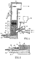
- FIG. 1 illustrates a plasma fired cupola 10 which bears many common aspects to the apparatus employed for the iron foundry melting and recycling of steel belted tires.
- the cupola itself is a vertical shaft 12 with a refractory lining 13.
- a charge door 14 for charging excavated landfill material (ELM) as well as reactive agents such as a carbonaceous fuel which may be coke or a mixture of coke and coal, normally the latter, and a fluxing agent such as limestone. Air also enters through the charge door 14.
- ELM excavated landfill material
- Proximate the bottom of the cupola 12 are disposed plasma torches 16 each within a tuyere 17 extending into the cupola and having a shroud nozzle 18.
- Each torch 16 is supplied with a gas such as air through line 16a that is introduced in an arc between energized, spaced, electrodes to be ionized and form a plasma.
- Blast air tangentially enters just in front of the torch 16 through line 18a and nozzle 18.
- the blast air is added to the plasma and is heated and then enters into the cupola 12 in its heated state.
- the air entering through line 18a may be at ambient temperature or preheated up to about 1200°F.
- the cupola 12 Above the cupola 12 is an afterburner chamber 20 into which the off gases from the cupola 12 rise.
- the afterburner is provided with a stack igniter 22 but it is not necessary to supply fuel in addition to the off gases themselves.
- the ELM can be fed directly into the charge door 14 such as by using a skip bucket carried by a skip hoist or by a feeder belt.
- the ELM does not have to be preprocessed to any appreciable degree in terms of sizing or drying and is generally used on an as received basis.
- the cupola shaft diameter is sized to accept the biggest size of ELM which might, for example, be an engine block or refrigerator. In other respects, it is of course suitable if desired to subject the ELM to a pretreatment through a shredder or the like to reduce the size of individual pieces; preferably the cupola is designed so that this is not necessary.
- An economical mix of coke and coal is also fed into the skip bucket which is then elevated and dumped into the charge door by means of a skip hoist.
- coke is the preferred fuel and reducing agent and will be referred to herein. As opposed to coal, it provides more firm support for the other solid materials added in a charge and ensures adequate gas flow. For economy, varying amounts of coal may be mixed with the coke. In general, the fuel should be at least about 25% coke.
- the cupola 12 filled with coke up to several inches above tuyere 17.
- the coke bed 30 is ignited by the plasma heated air which is fed at the bottom of the cupola through the tuyere 17.
- the charge material consisting of ELM, coke (which may include some coal), and the fluxing agent is fed through the charge door.
- This system start-up normally takes only about 2 to 3 hours.
- the coke besides providing the energy of combustion, also provides a porous matrix inside the cupola shaft so that the ELM does not form a mat and cause plugging.
- both coal and coke provide carbon monoxide to the off gas which upon ignition in the afterburner completely destroys the PCB's.
- No supplemental fuel is required to provide heat in the afterburner 20.
- a fuel such as natural gas is readily available and economical it may be burned to supply heat and allow a corresponding reduction in the amount of coke in the cupola.
- the ELM as it travels down the cupola shaft 12, is first heated by the hot gases rising from the melt zone at the bottom of the cupola. This countercurrent heat exchange is one of the primary reasons for the energy efficiency of the plasma fired cupola.
- the PCB's are evaporated from the ELM and exit the cupola along with the other off gases, typically CO, CO2, N2.
- the top gases rise to the afterburner unit 20 where they are mixed with the combustion air entering through the charge door 14 and ignited by the stack igniter 22 to produce sufficient temperature for destruction of PCB's.
- the standard requirement is that such materials be subjected to a temperature of at least about 2200°F for a time of at least about 2 seconds and these conditions can be adequately, readily met in the present process.
- the ELM Upon traveling down the cupola shaft 12, the ELM enters the melt zone (in coke bed 30 proximate to and above tuyere 17) where the temperatures are in the range of from about 3000°F to about 4500°F. All constituents of the ELM melt at this temperature and form a vitreous slag plus the metallic portion of the ELM that also melts.
- the temperature and chemistry of the melt zone are controlled (by air and coke supplied) to achieve desired performance.
- most oxides e.g., iron and copper are reduced to provide the metal itself in a molten state.
- the heavy metal oxides of metal such as chromium and nickel may not be reduced but instead are dissolved in the slag.
- Some metals, such as zinc and lead, are likely to have their oxides reduced and the metals vaporized. Such latter metals are reoxidized in the afterburner 20 and will be collected from the afterburner discharge.
- the plasma torch power is preferably adjusted so that silica (SiO2), contained within the ELM is reduced to produce silicon.
- the silicon dissolves in the molten metal and forms, with molten iron, a useful and valuable ferrous alloy that can be sold on the foundry market.
- the vitrified ELM and the metal is continuously tapped through a spout 24 at the bottom of the cupola using a skimmer 24a and dam 24b arrangement.
- the molten stream from the spout 24 is about 2500°-2800°F.
- the slag is separated from the metal by this arrangement to produce blocks of slag and metal ingots.
- Fig. 2 shows an enlarged view of a spout 24.
- Molten slag 40 and molten metal 42 collect at the bottom of the cupola shaft 12.
- the lighter slag 40' is confined by a skimmer 24a and is tapped off.
- the gases exiting the afterburner 20 may be exhausted to the atmosphere, preferably only after going through a scrubber or other air pollution control equipment with collection of flyash.
- the hot combustion gases exiting the afterburner 20 are sent to a recuperator to preheat the blast air and also the combustion air of the afterburner.
- the hot gases from the afterburner are sent to a boiler to generate steam which may be used for process requirements or to generate power.
- fly ash from the afterburner 20 or elsewhere, such as utility boilers and incinerators, through the nozzle 18 installed in the tuyere region at the base of the cupola. Bin 18b and line 18c is shown for this purpose.
- This material is simultaneously vitrified along with the ELM for convenient disposal.
- flyash containing, for example, oxides of lead or zinc may be fed directly into the molten slag at the bottom of the cupola 12 proximate the spout 24 or in the spout itself before the material solidifies. This helps to ensure such oxides are dissolved in the slag for safe disposal.
- the plasma fired cupola is a flexible apparatus suitable for use with a wide range of feed compositions.
- the fuel supplied with a charge of ELM provides carbon to produce sufficient amounts of carbon monoxide to serve as the fuel in the afterburner 20 for assured destruction of PCB's and the like.
- the carbon fuel (coke) in the charge make up about 6% or more, by weight, of the process material supplied into the cupola.
- ELM electrowetting fuel
- coke 30 supplied in the cupola
- a first layer of ELM 32 can be fed into the cupola, followed by a coke layer 33, then a limestone layer 34 followed by a coke layer 35. Then the sequence may be repeated up to near the charge door 14.
- a coke layer separates layers of the ELM and limestone materials, which may, if desired, be mixed together in a single layer.
- the coke (or carbon fuel) bed height is well regulated.
- the initial coke charge 30 fills the cupola up to a level above the tuyere 17 (essentially a hollow tube) through which the blast air heated by the torch 16 enters the cupola.
- a level of about five inches to about 10 inches above the top of the tuyere 17 is normally preferred to give a desirable ratio of CO to CO2.
- the initial coke bed height is maintained, with normal variations up and down, around that level of the charge material.
- the coke ratio blast rate and torch power is adjusted based on melt rate requirement such that the CO/CO2 molar ratio in the top gas is in the range of 0.2 to 3.0.
- the amount of limestone is preferably adjusted for optimum basicity to yield good flow characteristics in the slag at the moderate temperatures which are easily attained.
- Basicity is defined as the ratio: CaO% + MgO% SiO2% + Al2O3%
- the slag is highly viscous and flows very slowly. Above about 0.7, the slag very friable so it serves less well a an encapsulator of hazardous materials that may be contained in it. Therefore, it is preferred to have a basicity within the range from about 0.3 to about 0.7.
- the gas flow rate (through 18) is reduced to an even lower level than the case of foundry melting for awarding slag elutriation in the melt zone.
- the flow rate in the cupola is about 0.5 cubic feet per minute (per sq. in. of cupola cross-section) or less and preferably about 0.2 to about 1.0.
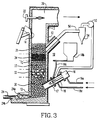
- Fig. 3 the system of Fig. 1 is shown with the addition of a recycle loop 50 that includes a draft fan 52 for recycling some of the off gases from the cupola 12 back to the torch nozzle 18.
- the recycle loop 50 also includes a trap 54 for particles (fly ash) that can be reinjected through bin 18b or can be injected into the slag, in addition to other forms of disposition.
- the recycle loop 50 is an option that is more beneficial if the ELM contains relatively larger quantities of oxides of valuable metals desired to be recovered. Oxides in the charge tend to be reduced by the carbon fuel but if excess air is present the reaction will tend to reverse and reform the metal oxides. To create a more strongly reducing atmosphere one may draw off some of CO and N and have it re-enter the nozzle to lower the relative amount of oxygen. Typically the gases exiting the cupola are at about 800°F and re-enter at about 200°F. The recycled off gases help promote the reduction reaction while permitting use of less coke than may be necessary if it alone were counted on to take care of the oxygen in the blast air.
- Fig. 4 shows a further variation referred to as a plasma-fired cupola with a "below charge take-off".
- the top of the cupola 12 is changed so the afterburner 20 receives off gases from a point below the charge level.
- a fan and air pollution control equipment, not shown, would be provided after the afterburner.
- a change door 14' is provided at the top that minimizes air entry.
- the door 14' is supported by a hoist cable 60 that in the closed position holds the door 14' against the door frame 62.
- a charge 64 of material is applied on the upper surface of the door. When the door is lowered, the material enters the cupola and becomes part of charge 64' which extends up past the gas take-off.
- the door 14' can be promptly closed so a highly reducing atmosphere is maintained.
- Example I has been actually performed and verified to process the material into a stream of lag and a stream of metal, essentially a ferrous alloy containing about 4% silicon.
- the off gases produced afterburner temperatures in excess of 2200°F.
Landscapes
- Engineering & Computer Science (AREA)
- Mechanical Engineering (AREA)
- General Engineering & Computer Science (AREA)
- Life Sciences & Earth Sciences (AREA)
- Environmental & Geological Engineering (AREA)
- Physics & Mathematics (AREA)
- Chemical & Material Sciences (AREA)
- Soil Sciences (AREA)
- Plasma & Fusion (AREA)
- Thermal Sciences (AREA)
- Chemical Kinetics & Catalysis (AREA)
- General Chemical & Material Sciences (AREA)
- Geochemistry & Mineralogy (AREA)
- Materials Engineering (AREA)
- Organic Chemistry (AREA)
- Processing Of Solid Wastes (AREA)
- Gasification And Melting Of Waste (AREA)
- Crucibles And Fluidized-Bed Furnaces (AREA)
- Plasma Technology (AREA)
Claims (18)
- Ein Prozeß zur Behandlung von ausgegrabenem Landfüllmaterial, kontaminiert mit toxischen und gefährlichen Substanzen, umfassend einen plasma-befeuerten Kupolofen, der einen vertikalen Kupolschaft mit einer oben angeordnetem Chargentür und einem Plasmabrenner, angeordnet nahe dem Boden des Kupolofens, aufweist, Erhitzen von Luft auf eine hohe Temperatur durch den Plasmabrenner und Liefern der erhitzten Luft in den Kupolofen, Bilden eines Bettes von kohlenstoffartigem Brennstoff in dem Kupolofen, erhitzt zur Verbrennung durch die erhitzte Luft, Liefern von Material, das verarbeitet werden soll, und reaktive Mittel durch die Chargentür des Kupolofens, wobei die reaktiven Mittel zusätzlichen kohlenstoffartigen Brennstoff, einschließlich Koks und Kohle, umfassen, Schmelzen des Materials in dem Kupolofen zur Bildung einer vitrösen Schlacke, Abziehen des Kupolofens, um die vitröse Schlacke herauszunehmen, der vitrösen Schlacke aus dem Kupolofen ermöglichen, abzukühlen und ein nicht gefährliches-festes Material zu erzeugen, wobei der Koks in dem kohlenstoffartigen Brennstoff ein Brennstoffbett mit einem wesentlichen Maß an Porosität für das Material in dem Kupolofen liefert, um eine Gasströmung hindurch sowie Solidität zur Stützung von zusätzlich zugefügtem Material zu ermöglichen, und in welchem die Versorgung von Material und reaktiven Mitteln in einer solchen Weise durchgeführt wird, um getrennte oder unterschiedliche Schichten vom Material und reaktiven Mitteln zu liefern; gekennzeichnet durch zu verarbeitendes Material, bestehend aus ausgegrabenem Landfüllmaterial, und daß der Prozeß weiterhin das Abziehen von Abgasen von dem Kupolofen zu einem Nachbrenner zur Zerstörung von irgendwelchen flüchtigen toxischen und gefährlichen Materialien, die in den Abgasen enthalten sind, umfaßt.
- Ein Prozeß nach Anspruch 1, dadurch gekennzeichnet, daß der kohlenstoffhaltige Brennstoff zur Bildung von Kohlenmonaxid führt, ausreichend, um den Nachbrenner mit Brennstoff zu versorgen, so daß der Nachbrenner eine Temperatur erreicht, ausreichend um die Abgase einer Temperatur von zumindest etwa 2200°F auszusetzen für eine Zeit von zumindest etwa 2 Sekunden zur ausreichenden Zerstörung von irgendwelchen darin enthaltenen PCB's.
- Ein Prozeß nach Anspruch 1 oder 2, dadurch gekennzeichnet, daß die reaktiven Mittel weiterhin ein Flußmittel umfassen, in welchem ein wesentlicher Teil des gelieferten Flußmittels Kalkstein ist.
- Ein Prozeß nach einem der Ansprüche 1 bis 3, dadurch gekennzeichnet, daß der Plasmabrenner ausreichend erhitzte Luft in den Kupolofen liefert, um eine Schmelzzone zu erzeugen, die eine Temperatur im Bereich von zumindest 3000°F bis 4000°F besitzt.
- Ein Prozeß nach Anspruch 1, dadurch gekennzeichnet, daß das Schmelzen des ausgegrabenen Landfüllmaterials eingeschmolzenes Metall zusätzlich zu der vitrösen Schlacke bildet, wobei das ausgegrabene Landfüllmaterial eine oder mehrere Siliziumverbindungen enthält, die innerhalb des Kupolofens reduziert werden, um Silizium zu liefern, gelöst in dem geschmolzenem Metall, wodurch eine Eisen-Silizium-Legierung gebildet wird.
- Ein Prozeß nach Anspruch 5, dadurch gekennzeichnet, daß der Prozeß weiterhin das Anzapfen des Kupolofens umfaßt, um geschmolzenes Metall und vitröse Schlacke davon abzuleiten, wobei der Kupolofen einen Schnabel mit einem Abstreifer und einem Damm für ein derartiges Abziehen aufweist.
- Ein Prozeß nach Anspruch 2, dadurch gekennzeichnet, daß die heißen Verbrennungsgase, die den Nachbrenner verlassen, einem Wärmeaustauscher zugeführt werden, um eine Flüssigkeit zu erhitzen, welche in dem Prozeß zur Behandlung von ausgegrabenem Landfüllmaterial oder für andere Zwecke verwendet wird.
- Ein Prozeß nach Anspruch 1, dadurch gekennzeichnet, daß zusätzlich zu erhitzter Blasluft ein feines Abfallmaterial in den Kupolofen eingeführt wird und in dem Kupolofen zusammen mit dem ausgegrabenem Landfüllmateril vitrifiziert wird.
- Ein Prozeß nach Anspruch 6, dadurch gekennzeichnet, daß zusätzlich Abfallmaterial durch die Zufuhrtür des Kupolofens zusätzlich zudem Landfüllmaterial und dem reaktiven Mittel geliefert wird.
- Ein Prozeß nach einem der Ansprüche 1 bis 9, dadurch gekennzeichnet, daß der zusätzlich kohlenstoffartige Brennstoff, geliefert zusammen mit dem ausgegrabenem Landfüllmaterial, in einer Menge von zumindest 6% der Gesamtcharge ist, um einen ausreichenden Kohlenstoff zu liefern, um Kohlenmonoxid zu erzeugen, verwendet als Brennstoff in dem Nachbrenner.
- Ein Prozeß nach Anspruch 1, dadurch gekennzeichnet, daß das reaktive Mittel Koks und Kalkstein umfaßt, welches zusammen mit Landfüllmaterial geliefert wird, um alternierende und unterschiedliche Schichten von den Materialien in einer vorbestimmten Aufeinanderfolge zu liefern, so daß eine Schicht von Koks vorgesehen wird, um Schichten der anderen Materialien zu trennen.
- Ein Prozeß nach einem der Ansprüche 1 bis 11, dadurch gekennzeichnet, daß die Gasströmung in dem Kupolofen gesteuert wird zu einer Höhe von etwa 0,6 Kubikfuß pro Minute oder weniger.
- Ein Prozeß nach einem der Ansprüche 3 bis 12, dadurch gekennzeichnet, daß die gelieferte Menge des Flußmittels gesteuert wird, um eine Basizität in der vitrifizierten Schlacke von etwa 0,3 bis etwa 0,7 zu erzeugen.
- Ein Prozeß nach einem der Ansprüche 1 bis 13, gekennzeichnet durch ein heißes Bett von Kohlenstoffbrennstoff in dem Kupolofen bis zu einer Höhe oberhalb und nahe eines Blasrohrs, von dem plasma-erhitzte Luft in den Kupolofen eintritt, um eine Schmelzzone nahe der Oberseite des heißen Bettes zu bilden, bei einem Temperaturbereich von 3000°F bis 4500°F, und Kohlenmonoxid zu erzeugen, Zuführen einer Charge von ausgegrabenem Landfüllmaterial, Flußmittel und zusätzlichen Kohlenstoffbrennstoff auf das heiße Bett, um Material zu entwickeln, das an der Schmelzzonentemperatur verdampft, einschließlich irgendwelchen darin enthaltenden PCB's, um die Verbindungen von einem oder mehreren Metallen der Gruppe von Eisen, Kupfer, Zink und Blei zu reduzieren, und Verbindungen von irgendwelchen Metallen der Gruppe von Chrom und Nickel zu reduzieren, und um geschmolzenes Metall und vitröse Schlacke zu erzeugen.
- Ein Prozeß nach Anspruch 14, dadurch gekennzeichnet, daß den entwickelten Dämpfen und dem Kohlenmonoxid erlaubt wird, zu einem Nachbrenner aufzusteigen, wo Bedingungen eine Verbrennung und eine Aussetzung der Dämpfe einer Temperatur von zumindest etwa 2200°F für eine Zeitdauer von zumindest etwa 2 Sekunden erzeugen.
- Ein Prozeß nach Anspruch 14, wobei das geschmolzene Metall ein Metall umfaßt, das aus der Reduktion von Verbindungen von Metallen aus der Gruppe einschließlich Eisen und Kupfer resultiert.
- Ein Verfahren nach Anspruch 14, wobei die Reduktion von Verbindungen von Metallen von der Gruppe bestehend aus Zink, Kadium und Blei in der Schmelzzone zu der Verdampfung derartiger Metalle führt, welche mit anderen entwickelten Dämpfen und Kohlenmonoxid zu einem Nachbrenner aufsteigen, wo die Oxide dieser Metalle gebildet und nachfolgend gesammelt werden.
- Ein plasma-befeuertes Kupolofensystem, angeordnet zur Behandlung von ausgegrabenem Landfüllmaterial, bestehend aus einem vertikalen Schaft, einer an dem oberen Teil des Schaftes angeordneten Zufuhrtür, einem Blasrohr nahe dem Boden des Schaftes, zumindest einem Plasmabrenner und einer Manteldüse, angeordnet kolinear mit dem Blasrohr, Luftzufuhrleitungen in den Plasmabrenner bzw. die Manteldüse, Einrichtungen zur Erregung des Brenners und zur Reduzierung eines Plasmas von darin enthaltener Luft, die dann Luft erhitzt, welche in der Düse geliefert wird, einem Bett von Kohlenstoffbrennstoff, gekennzeichnet durch zumindest etwa 25% Koks in dem Schaft, der sich von dem Boden davon bis zu einer Höhe nahe und oberhalb der Blasdüse erstreckt, um so ein Ausmaß von Porosität zu dem Material in dem Kupolofen zu liefern, wobei der Schaft ein Chargenmaterial auf dem Bett von Kohlenstoffbrennstoff enthält, wobei das Chargenmaterial Material umfaßt, das zu verarbeiten ist, zusätzlich Kohlenstoffbrennstoff, und ein Flußmittel, wobei der Schaft einen Schnabel an seinem untersten Bereich zur Lieferung von geschmolzener Schlacke und erzeugten Metall von dem Chargenmaterial besitzt; dadurch gekennzeichnet, daß das Material, das verarbeitet werden soll, ausgegrabenes Landfüllmaterial umfaßt, und daß der Schaft eine Nachbrennkammer in seinem obersten Bereich mit einem Schornsteinzünder darin aufweist, wobei das Chargenmaterial auf dem Bett von Kohlenstoffbrennstoff Abgase erzeugt, die in dem Nachbrenner verbrannt werden.
Applications Claiming Priority (2)
| Application Number | Priority Date | Filing Date | Title |
|---|---|---|---|
| US07/343,694 US4998486A (en) | 1989-04-27 | 1989-04-27 | Process and apparatus for treatment of excavated landfill material in a plasma fired cupola |
| US343694 | 1994-11-22 |
Publications (3)
| Publication Number | Publication Date |
|---|---|
| EP0395397A2 EP0395397A2 (de) | 1990-10-31 |
| EP0395397A3 EP0395397A3 (de) | 1991-09-25 |
| EP0395397B1 true EP0395397B1 (de) | 1993-06-30 |
Family
ID=23347216
Family Applications (1)
| Application Number | Title | Priority Date | Filing Date |
|---|---|---|---|
| EP90304492A Expired - Lifetime EP0395397B1 (de) | 1989-04-27 | 1990-04-26 | Verfahren und Vorrichtung zur Behandlung von ausgegrabenen Deponiematerialien in einem plasmabeheizten Kupolofen |
Country Status (5)
| Country | Link |
|---|---|
| US (1) | US4998486A (de) |
| EP (1) | EP0395397B1 (de) |
| JP (1) | JP3012665B2 (de) |
| CA (1) | CA2013591A1 (de) |
| DE (1) | DE69002082T2 (de) |
Families Citing this family (71)
| Publication number | Priority date | Publication date | Assignee | Title |
|---|---|---|---|---|
| YU46333B (sh) * | 1987-04-30 | 1993-05-28 | Oy Partek Ab | Talilna pec |
| US5319176A (en) * | 1991-01-24 | 1994-06-07 | Ritchie G. Studer | Plasma arc decomposition of hazardous wastes into vitrified solids and non-hazardous gasses |
| DE4104507C2 (de) * | 1991-02-14 | 1997-08-07 | Elsner Emil Dr Ing | Verfahren und Vorrichtung zum Verarbeiten von Abfallstoffen, insbesondere Hausmüll, zu einem brennbaren Gasgemisch, Metallen und Schlacke |
| US5103578A (en) * | 1991-03-26 | 1992-04-14 | Amoco Corporation | Method and apparatus for removing volatile organic compounds from soils |
| US5143000A (en) * | 1991-05-13 | 1992-09-01 | Plasma Energy Corporation | Refuse converting apparatus using a plasma torch |
| US5262107A (en) * | 1991-06-25 | 1993-11-16 | Applied Extrusion Technologies, Inc. | Method of making apertured film fabrics |
| US5423676A (en) * | 1992-03-30 | 1995-06-13 | Osaka Gas Co., Ltd. | Waste melting furnace |
| US5439498A (en) * | 1992-11-10 | 1995-08-08 | Exide Corporation | Process and system for the on-site remediation of lead-contaminated soil and waste battery casings |
| US5284503A (en) * | 1992-11-10 | 1994-02-08 | Exide Corporation | Process for remediation of lead-contaminated soil and waste battery |
| US5766303A (en) * | 1992-11-10 | 1998-06-16 | Exide Corporation | Process for the remediation of lead-contaminated soil and waste battery casings |
| DE4317145C1 (de) * | 1993-05-24 | 1994-04-28 | Feustel Hans Ulrich Dipl Ing | Verfahren und Einrichtung zur Entsorgung unterschiedlich zusammengesetzter Abfallmaterialien |
| US5399833A (en) * | 1993-07-02 | 1995-03-21 | Camacho; Salvador L. | Method for vitrification of fine particulate matter and products produced thereby |
| US5430236A (en) * | 1993-08-13 | 1995-07-04 | Pedro B. de Macedo | Method for vitrifying ash |
| WO1997014528A1 (en) * | 1993-08-19 | 1997-04-24 | Refranco Corp. | Plasmalysis treatment method for waste matter |
| US5403991A (en) * | 1993-08-19 | 1995-04-04 | Refranco Corp. | Reactor and method for the treatment of particulate matter by electrical discharge |
| DE4339675C1 (de) * | 1993-11-22 | 1995-05-04 | Messer Griesheim Gmbh | Verfahren und Vorrichtung zum Einschmelzen von festen Verbrennungsrückständen |
| US5534659A (en) * | 1994-04-18 | 1996-07-09 | Plasma Energy Applied Technology Incorporated | Apparatus and method for treating hazardous waste |
| US5615627A (en) * | 1995-02-23 | 1997-04-01 | Biocon, Incorporated | Method and apparatus for destruction of waste by thermal scission and chemical recombination |
| US5728193A (en) * | 1995-05-03 | 1998-03-17 | Philip Services Corp. | Process for recovering metals from iron oxide bearing masses |
| WO1997027903A1 (en) * | 1996-01-30 | 1997-08-07 | Vial Jean Luc | Apparatus and method for treating solids |
| KR970069162A (ko) * | 1996-04-30 | 1997-11-07 | 이대원 | 플라즈마(Plasma)를 이용한 폴리클로리네이티드바이페닐(Poly Chlorinated Bipheny)폐기물 처리방법 |
| US6355904B1 (en) | 1996-06-07 | 2002-03-12 | Science Applications International Corporation | Method and system for high-temperature waste treatment |
| US5827012A (en) * | 1997-01-06 | 1998-10-27 | Circeo, Jr.; Louis J. | Thermal plasma conversion of local soils into construction materials |
| US6119607A (en) * | 1997-05-09 | 2000-09-19 | Corporation De L'ecole Polytechnique | Granular bed process for thermally treating solid waste in a flame |
| FR2764877B1 (fr) * | 1997-06-20 | 1999-09-03 | Europlasma | Procede de vitrification d'un materiau pulverulent et dispositif pour la mise en oeuvre de ce procede |
| US6096379A (en) * | 1998-03-20 | 2000-08-01 | Eckhoff; Paul S. | Radiation processing apparatus and method |
| US5882737A (en) * | 1998-03-20 | 1999-03-16 | Eckhoff; Paul S. | Apparatus and method for radiation processing of materials |
| IT1313272B1 (it) * | 1999-07-29 | 2002-07-17 | Rgr Ambiente Reattori Gassific | Procedimento e dispositivo per la pirolisi e gassificazione di rifiuti |
| US6551563B1 (en) | 2000-09-22 | 2003-04-22 | Vanguard Research, Inc. | Methods and systems for safely processing hazardous waste |
| US6514469B1 (en) | 2000-09-22 | 2003-02-04 | Yuji Kado | Ruggedized methods and systems for processing hazardous waste |
| US7857972B2 (en) | 2003-09-05 | 2010-12-28 | Foret Plasma Labs, Llc | Apparatus for treating liquids with wave energy from an electrical arc |
| US8764978B2 (en) | 2001-07-16 | 2014-07-01 | Foret Plasma Labs, Llc | System for treating a substance with wave energy from an electrical arc and a second source |
| US8981250B2 (en) | 2001-07-16 | 2015-03-17 | Foret Plasma Labs, Llc | Apparatus for treating a substance with wave energy from plasma and an electrical Arc |
| US7622693B2 (en) * | 2001-07-16 | 2009-11-24 | Foret Plasma Labs, Llc | Plasma whirl reactor apparatus and methods of use |
| US10188119B2 (en) | 2001-07-16 | 2019-01-29 | Foret Plasma Labs, Llc | Method for treating a substance with wave energy from plasma and an electrical arc |
| US20050070751A1 (en) * | 2003-09-27 | 2005-03-31 | Capote Jose A | Method and apparatus for treating liquid waste |
| SG111177A1 (en) * | 2004-02-28 | 2005-05-30 | Wira Kurnia | Fine particle powder production |
| JP2005262099A (ja) * | 2004-03-18 | 2005-09-29 | Nippon Steel Corp | 有機汚染廃棄物の無害化処理方法及び処理装置 |
| US6971323B2 (en) | 2004-03-19 | 2005-12-06 | Peat International, Inc. | Method and apparatus for treating waste |
| AR052204A1 (es) * | 2005-02-10 | 2007-03-07 | Wyeth Corp | Aparato y metodo para procesar productos alimenticios fluidos por radiacion |
| US7832344B2 (en) * | 2006-02-28 | 2010-11-16 | Peat International, Inc. | Method and apparatus of treating waste |
| WO2008008104A2 (en) | 2006-04-05 | 2008-01-17 | Foret Plasma Labs, Llc | System, method and apparatus for treating liquids with wave energy from plasma |
| US7571687B2 (en) * | 2006-08-08 | 2009-08-11 | Cornellier J Rene | Apparatus for destruction of organic pollutants |
| US7632394B2 (en) * | 2007-05-29 | 2009-12-15 | Westinghouse Plasma Corporation | System and process for upgrading heavy hydrocarbons |
| CN100560238C (zh) * | 2007-09-13 | 2009-11-18 | 浙江大学 | 两步式城镇生活垃圾填埋处理系统及其方法 |
| CN101983087B (zh) * | 2008-02-08 | 2013-04-17 | Peat国际公司 | 处理废物的方法和设备 |
| DE102008010919A1 (de) | 2008-02-25 | 2009-09-03 | Markus Franssen | Abfallverwertungsanlage zur Erzeugung von Energie |
| JP5415006B2 (ja) * | 2008-03-26 | 2014-02-12 | 株式会社神鋼環境ソリューション | Pcb汚染物処理方法 |
| DE102009014410A1 (de) | 2008-03-31 | 2009-10-01 | Etag Production Gmbh | Abfallverwertungsanlage zur Erzeugung von Energie |
| US20090307974A1 (en) * | 2008-06-14 | 2009-12-17 | Dighe Shyam V | System and process for reduction of greenhouse gas and conversion of biomass |
| GB2465603B (en) * | 2008-11-24 | 2010-10-13 | Tetronics Ltd | Method for recovery of metals |
| US9222038B2 (en) * | 2009-02-11 | 2015-12-29 | Alter Nrg Corp. | Plasma gasification reactor |
| US20100199556A1 (en) * | 2009-02-11 | 2010-08-12 | Dighe Shyam V | Plasma gasification reactor |
| US20100199557A1 (en) * | 2009-02-11 | 2010-08-12 | Dighe Shyam V | Plasma gasification reactor |
| JP5281443B2 (ja) * | 2009-03-11 | 2013-09-04 | 新日鉄住金エンジニアリング株式会社 | 廃棄物溶融炉への可燃性ダスト吹き込み方法 |
| US8671855B2 (en) | 2009-07-06 | 2014-03-18 | Peat International, Inc. | Apparatus for treating waste |
| US20120061618A1 (en) | 2010-09-11 | 2012-03-15 | James Santoianni | Plasma gasification reactors with modified carbon beds and reduced coke requirements |
| US9005320B2 (en) | 2011-02-05 | 2015-04-14 | Alter Nrg Corp. | Enhanced plasma gasifiers for producing syngas |
| US11073049B2 (en) * | 2011-02-10 | 2021-07-27 | Plasma Tech Holdings, Llc | Inductive bath plasma cupola |
| JP5708119B2 (ja) * | 2011-03-25 | 2015-04-30 | 株式会社Ihi | 微粉炭バーナ |
| GB2490175A (en) * | 2011-04-21 | 2012-10-24 | Tetronics Ltd | Treatment of waste |
| US9574770B2 (en) | 2012-04-17 | 2017-02-21 | Alter Nrg Corp. | Start-up torch |
| US9499443B2 (en) | 2012-12-11 | 2016-11-22 | Foret Plasma Labs, Llc | Apparatus and method for sintering proppants |
| WO2014165255A1 (en) | 2013-03-12 | 2014-10-09 | Foret Plasma Labs, Llc | Apparatus and method for sintering proppants |
| KR102655624B1 (ko) | 2017-10-13 | 2024-04-08 | 파이로제네시스 캐나다 인코퍼레이티드 | 폐기물 용융 및 가스화를 위한 dc 아크 퍼니스 |
| US11530158B2 (en) * | 2019-08-22 | 2022-12-20 | Xaris Holdings, LLC | Amorphous silica products, articles, and particles and methods of producing amorphous silica products, articles, and particles from concrete |
| CN113483339B (zh) * | 2021-06-16 | 2023-08-25 | 江苏凯丰新能源科技有限公司 | 资源化处理铝电解碳电极废料的连续式电热炉及方法 |
| KR102707861B1 (ko) * | 2022-02-15 | 2024-09-19 | 한국핵융합에너지연구원 | 토치 결합용 자동 개폐식 용융로 포트 및 이를 이용한 플라즈마 용융로 |
| EP4394299A1 (de) * | 2022-12-30 | 2024-07-03 | S.A. Lhoist Recherche Et Developpement | Verfahren zum brennen von carbonisierten mineralsteinen in einem ringförmigen vertikalen ofen und implementierter ofen |
| EP4394296A1 (de) * | 2022-12-30 | 2024-07-03 | S.A. Lhoist Recherche Et Developpement | Verfahren zum kalzinieren von karbonisierten mineralsteinen in einem regenerativen ofen mit parallelem fluss und implementierter ofen |
| EP4394295A1 (de) * | 2022-12-30 | 2024-07-03 | S.A. Lhoist Recherche Et Developpement | Verfahren zum brennen von carbonisierten mineralsteinen in einem ringförmigen vertikalen ofen und implementierter ofen |
Family Cites Families (14)
| Publication number | Priority date | Publication date | Assignee | Title |
|---|---|---|---|---|
| US3697256A (en) * | 1971-02-08 | 1972-10-10 | Isaiah B Engle | Method of incinerating refuse |
| BE786025A (fr) * | 1971-07-09 | 1973-01-08 | Union Carbide Corp | Procede d'incineration d'ordures |
| US4078914A (en) * | 1973-05-30 | 1978-03-14 | Louis Gold | Gasification of coal and refuse in a vertical shaft furnace |
| DE2904855C3 (de) * | 1979-02-09 | 1981-12-03 | Modern Equipment Co., Port Washington, Wis. | Koksbeheizter-Kupolofen |
| US4346661A (en) * | 1980-03-20 | 1982-08-31 | Osaka Gas Kabushiki Kaisha | Furnace for treating industrial wastes |
| JPS5712216A (en) * | 1980-06-25 | 1982-01-22 | Osaka Gas Co Ltd | Method of melting waste |
| SE451033B (sv) * | 1982-01-18 | 1987-08-24 | Skf Steel Eng Ab | Sett och anordning for omvandling av avfallsmaterial med plasmagenerator |
| US4530101A (en) * | 1983-04-15 | 1985-07-16 | Westinghouse Electric Corp. | Electric arc fired cupola for remelting of metal chips |
| DE3611429A1 (de) * | 1985-02-15 | 1986-11-06 | SKF Steel Engineering AB, Hofors | Verfahren zur abfallzersetzung |
| FR2610087B1 (fr) * | 1987-01-22 | 1989-11-24 | Aerospatiale | Procede et dispositif pour la destruction de dechets solides par pyrolyse |
| US4761793A (en) * | 1987-05-08 | 1988-08-02 | Electric Power Research Institute | Plasma fired feed nozzle |
| US4780132A (en) * | 1987-05-08 | 1988-10-25 | Electric Power Research Institute | Plasma fired cupola |
| US4769065A (en) * | 1987-05-08 | 1988-09-06 | Electric Power Research Institute | Control of a plasma fired cupola |
| US4780130A (en) * | 1987-07-22 | 1988-10-25 | Gte Laboratories Incorporated | Process to increase yield of fines in gas atomized metal powder using melt overpressure |
-
1989
- 1989-04-27 US US07/343,694 patent/US4998486A/en not_active Expired - Lifetime
-
1990
- 1990-04-02 CA CA002013591A patent/CA2013591A1/en not_active Abandoned
- 1990-04-25 JP JP2111594A patent/JP3012665B2/ja not_active Expired - Lifetime
- 1990-04-26 EP EP90304492A patent/EP0395397B1/de not_active Expired - Lifetime
- 1990-04-26 DE DE90304492T patent/DE69002082T2/de not_active Expired - Fee Related
Also Published As
| Publication number | Publication date |
|---|---|
| EP0395397A2 (de) | 1990-10-31 |
| JPH02298717A (ja) | 1990-12-11 |
| CA2013591A1 (en) | 1990-10-27 |
| DE69002082D1 (de) | 1993-08-05 |
| US4998486A (en) | 1991-03-12 |
| EP0395397A3 (de) | 1991-09-25 |
| DE69002082T2 (de) | 1994-01-27 |
| JP3012665B2 (ja) | 2000-02-28 |
Similar Documents
| Publication | Publication Date | Title |
|---|---|---|
| EP0395397B1 (de) | Verfahren und Vorrichtung zur Behandlung von ausgegrabenen Deponiematerialien in einem plasmabeheizten Kupolofen | |
| US5042964A (en) | Flash smelting furnace | |
| JP2966219B2 (ja) | スクラップ連続予熱方法およびその装置 | |
| EP0625216B1 (de) | Verfahren zur entgiftung von blei-kontaminierten erdboden und gebrauchten batteriekästen | |
| US6173002B1 (en) | Electric arc gasifier as a waste processor | |
| US5281790A (en) | Process of immobilizing ashes by vitrification thereof in a plasma reactor | |
| EP0330872A2 (de) | Verfahren zur kontinuierlichen Agglomeration von Schwermetallen enthalten in der Asche einer Müllverbrennungsanlage | |
| EP0400925A2 (de) | Verfahren und Anlage zum Schmelzen verunreinigter metallischer Abfälle | |
| US5605104A (en) | Method and device for melting down solid combustion residues | |
| US5728193A (en) | Process for recovering metals from iron oxide bearing masses | |
| BE1027793B1 (nl) | Verbeterde Oven voor het Uitroken met Plasma Inductie | |
| US5685244A (en) | Gas-fired smelting apparatus and process | |
| CA2154715C (en) | Method of incinerating and melting wastes and apparatus therefor | |
| US4780132A (en) | Plasma fired cupola | |
| JP2001221418A (ja) | 廃電池の処理炉 | |
| JP3962178B2 (ja) | 有害物の処理方法およびその装置 | |
| JP2023526299A (ja) | 廃棄物を分離するための方法及び工業プラント | |
| CN111623353A (zh) | 一种针对垃圾的熔融减量化处理系统 | |
| JPH08200637A (ja) | 溶融炉 | |
| JP2000171015A (ja) | 廃棄物の焼却方法及び装置 | |
| EP2587145A1 (de) | Verfahren zur kontaminationsfreien thermischen verarbeitung von feststoffhausmüll und anlage zur ausführung dieses verfahrens | |
| JP2000167515A (ja) | 廃棄物の処理方法 | |
| JPH09189412A (ja) | シュレッダーダストの燃焼溶融処理方法 | |
| JP2002061815A (ja) | 廃棄物焼却方法および装置 | |
| JPH11182828A (ja) | 直接溶融炉及び廃棄物の処理方法 |
Legal Events
| Date | Code | Title | Description |
|---|---|---|---|
| PUAI | Public reference made under article 153(3) epc to a published international application that has entered the european phase |
Free format text: ORIGINAL CODE: 0009012 |
|
| AK | Designated contracting states |
Kind code of ref document: A2 Designated state(s): BE DE FR GB IT NL |
|
| PUAL | Search report despatched |
Free format text: ORIGINAL CODE: 0009013 |
|
| AK | Designated contracting states |
Kind code of ref document: A3 Designated state(s): BE DE FR GB IT NL |
|
| 17P | Request for examination filed |
Effective date: 19920319 |
|
| 17Q | First examination report despatched |
Effective date: 19920602 |
|
| GRAA | (expected) grant |
Free format text: ORIGINAL CODE: 0009210 |
|
| AK | Designated contracting states |
Kind code of ref document: B1 Designated state(s): BE DE FR GB IT NL |
|
| ET | Fr: translation filed | ||
| REF | Corresponds to: |
Ref document number: 69002082 Country of ref document: DE Date of ref document: 19930805 |
|
| ITF | It: translation for a ep patent filed | ||
| PLBE | No opposition filed within time limit |
Free format text: ORIGINAL CODE: 0009261 |
|
| STAA | Information on the status of an ep patent application or granted ep patent |
Free format text: STATUS: NO OPPOSITION FILED WITHIN TIME LIMIT |
|
| 26N | No opposition filed | ||
| PGFP | Annual fee paid to national office [announced via postgrant information from national office to epo] |
Ref country code: NL Payment date: 19990322 Year of fee payment: 10 |
|
| PGFP | Annual fee paid to national office [announced via postgrant information from national office to epo] |
Ref country code: BE Payment date: 19990511 Year of fee payment: 10 |
|
| PG25 | Lapsed in a contracting state [announced via postgrant information from national office to epo] |
Ref country code: BE Free format text: LAPSE BECAUSE OF NON-PAYMENT OF DUE FEES Effective date: 20000430 |
|
| BERE | Be: lapsed |
Owner name: WESTINGHOUSE ELECTRIC CORP. Effective date: 20000430 |
|
| PG25 | Lapsed in a contracting state [announced via postgrant information from national office to epo] |
Ref country code: NL Free format text: LAPSE BECAUSE OF NON-PAYMENT OF DUE FEES Effective date: 20001101 |
|
| NLV4 | Nl: lapsed or anulled due to non-payment of the annual fee |
Effective date: 20001101 |
|
| REG | Reference to a national code |
Ref country code: GB Ref legal event code: IF02 |
|
| PGFP | Annual fee paid to national office [announced via postgrant information from national office to epo] |
Ref country code: GB Payment date: 20030313 Year of fee payment: 14 |
|
| PGFP | Annual fee paid to national office [announced via postgrant information from national office to epo] |
Ref country code: FR Payment date: 20030403 Year of fee payment: 14 |
|
| PGFP | Annual fee paid to national office [announced via postgrant information from national office to epo] |
Ref country code: DE Payment date: 20030430 Year of fee payment: 14 |
|
| PG25 | Lapsed in a contracting state [announced via postgrant information from national office to epo] |
Ref country code: GB Free format text: LAPSE BECAUSE OF NON-PAYMENT OF DUE FEES Effective date: 20040426 |
|
| PG25 | Lapsed in a contracting state [announced via postgrant information from national office to epo] |
Ref country code: DE Free format text: LAPSE BECAUSE OF NON-PAYMENT OF DUE FEES Effective date: 20041103 |
|
| GBPC | Gb: european patent ceased through non-payment of renewal fee |
Effective date: 20040426 |
|
| PG25 | Lapsed in a contracting state [announced via postgrant information from national office to epo] |
Ref country code: FR Free format text: LAPSE BECAUSE OF NON-PAYMENT OF DUE FEES Effective date: 20041231 |
|
| REG | Reference to a national code |
Ref country code: FR Ref legal event code: ST |
|
| PGFP | Annual fee paid to national office [announced via postgrant information from national office to epo] |
Ref country code: IT Payment date: 20090414 Year of fee payment: 20 |