EP0391647A2 - Appareil de calibration d'un capteur de vitesse angulaire d'un système de navigation autonome - Google Patents
Appareil de calibration d'un capteur de vitesse angulaire d'un système de navigation autonome Download PDFInfo
- Publication number
- EP0391647A2 EP0391647A2 EP90303527A EP90303527A EP0391647A2 EP 0391647 A2 EP0391647 A2 EP 0391647A2 EP 90303527 A EP90303527 A EP 90303527A EP 90303527 A EP90303527 A EP 90303527A EP 0391647 A2 EP0391647 A2 EP 0391647A2
- Authority
- EP
- European Patent Office
- Prior art keywords
- heading
- angular
- vehicle
- velocity
- location
- Prior art date
- Legal status (The legal status is an assumption and is not a legal conclusion. Google has not performed a legal analysis and makes no representation as to the accuracy of the status listed.)
- Granted
Links
Images


Classifications
-
- G—PHYSICS
- G01—MEASURING; TESTING
- G01C—MEASURING DISTANCES, LEVELS OR BEARINGS; SURVEYING; NAVIGATION; GYROSCOPIC INSTRUMENTS; PHOTOGRAMMETRY OR VIDEOGRAMMETRY
- G01C17/00—Compasses; Devices for ascertaining true or magnetic north for navigation or surveying purposes
- G01C17/38—Testing, calibrating, or compensating of compasses
-
- G—PHYSICS
- G01—MEASURING; TESTING
- G01C—MEASURING DISTANCES, LEVELS OR BEARINGS; SURVEYING; NAVIGATION; GYROSCOPIC INSTRUMENTS; PHOTOGRAMMETRY OR VIDEOGRAMMETRY
- G01C21/00—Navigation; Navigational instruments not provided for in groups G01C1/00 - G01C19/00
- G01C21/26—Navigation; Navigational instruments not provided for in groups G01C1/00 - G01C19/00 specially adapted for navigation in a road network
- G01C21/28—Navigation; Navigational instruments not provided for in groups G01C1/00 - G01C19/00 specially adapted for navigation in a road network with correlation of data from several navigational instruments
- G01C21/30—Map- or contour-matching
Definitions
- the present invention relates to a calibration apparatus of an angular-velocity sensor (rate gyro) which is used in a self-contained navigational system as one of heading sensors.
- rate gyro angular-velocity sensor
- a variety of automatic vehicle navigational systems has been developed and used to provide information about the actual location of a vehicle as it moves over streets.
- dead reckoning in which the vehicle is tracked by advancing a “dead reckoned position” from measured distances and courses or headings.
- a system based upon dead reckoning principles may, for example, detect the distance travelled and heading of the vehicle using distance and heading sensors on the vehicle.
- the heading sensor used in dead reckoning may comprise a magnetic sensor or turning-angle sensor.
- a reading error of more than 10° tends to occur due to the distortion of earth's magnetism and influence of external magnetic fields, and spurious magnetic fields associated with the vehicle have also to be compensated.
- the turning-angle sensor there is used a differential odmeter for detecting a difference of rotation between the left and right wheels. Since the turning-angle sensor detects the rotation of tires, it has its disadvantage in that there occur errors caused by a change or distortion in tire radius, slips and the like.
- angular-velocity sensors such as optical fiber gyros, vibration gyros and coma-type gyros which detect directly rotational angular velocities.
- optical fiber gyro laser light is transmitted through an optical fiber ring in the clockwise direction and anticlockwise direction. If the optical fiber ring is rotated, then the lights in the both directions become different in time to pass through the optical path. This time difference is detected as a phase difference.
- the vibration gyro is one wherein a rotational angular velocity is detected by detecting a change of the vibration distribution of a particle vibrating in a container, since the particle disposed in rotational coordinates is subjected to Coriolis force.
- the errors involved in the angular velocity detected by the angular-velocity sensor are relatively small. However, if an error is involved in an initial heading used in obtaining the angular velocity by integrating the sensor output, this error will be fixed thereafter. That is to say, even if the detected angular velocity is accurate, the distinctive features of the angular-velocity sensor cannot be utilized if the initial heading is inaccurate. On the other hand, if the vehicle heading is corrected to match with the heading obtained from the magnetic sensor, it will be subjected to the distortion of earth's magnetic field in that place. In addition, in a method wherein a vehicle is stopped on a road to match with the road heading on a map, stopping the vehicle is troublesome, and an accurate calibration cannot be performed since the method depends upon the position of the vehicle stopped on the road.
- an object of the present invention to provide an improved calibration apparatus which is capable of automatically calibrating the output of an angular-velocity sensor which is used in a self-contained navigational system using map matching.
- a calibration apparatus of an angular-velocity sensor used in the self-contained navigational system comprises: an angular-velocity detection sensor 15 for detecting a heading of the vehicle; angular-velocity detection means 1 for calculating an angular velocity from an output signal of the angular-velocity detection sensor 15; integration means 2 for calculating a current heading of the vehicle by integrating the angular velocity and by adding the integrated angular velocity to the previous heading of the vehicle; and heading correction means 4 for calculating a difference between a heading output ⁇ r of the integration means 2 and a heading output ⁇ e of the location and heading detection means 3, for calculating
- the output of the angular-velocity detection sensor 15 is detected at all times and the angular velocity d ⁇ r/dt is calculated by the angular-velocity detection means 1.
- the angular velocity d ⁇ r/dt is then integrated and the integrated angular velocity is added to the previous heading of the vehicle by the integration means 2 to calculate a current heading ⁇ r of the vehicle.
- the current heading ⁇ r of the vehicle is supplied as base data of map matching to the location and heading detection means 3.
- the heading output ⁇ e obtained from the location and heading detection means 3 with the aid of the map matching is inputted to the heading correction means 4, stogether with the current heading ⁇ r obtained from the integration means 2.
- the heading correction means 4 calculates the difference between the heading output ⁇ r of the integration means 2 and the heading output ⁇ e of the location and heading detection means 3. If necessary, this difference is accumulated over the distances travelled by the vehicle. The reason that the difference is accumulated is that the accuracy of data is increased, since errors resulting from various factors are involved in the difference not accumulated.
- the correction value ⁇ for correcting the heading output ⁇ r of the integration means 2 is calculated from the difference or an accumulated value of the difference, and fed back to the integration means 2.
- the integration means 2 corrects the current heading ⁇ r with the correction value ⁇ and the corrected heading is supplied as base data of the map matching to the location and heading detection means 3, the accuracy of the map matching can be enhanced.
- the calibration apparatus of the angular-velocity sensor comprises: an angular-velocity detection sensor 15 for detecting a heading of the vehicle; angular-velocity detection means 1 for calculating an angular velocity from an output signal of the angular-velocity detection sensor 15; integration means 2 for calculating a current heading of the vehicle by integrating the angular velocity and by adding the integrated angular velocity to the previous heading of the vehicle; and heading correction means 7 which, when it has detected a turning of the vehicle, calculates a first change ⁇ r of a heading output ⁇ r obtained from the integration means 2 and a second change ⁇ e of a heading output ⁇ e obtained from the location and heading detection means 3, and which calculates a correction value ⁇ for correcting the angular velocity of the angular-velocity detection
- the calibration apparatus shown in Fig. 2 is similar to that of Fig. 1 except the heading correction means 7.
- the heading correction means 7 When the heading correction means 7 has detected a turning of the vehicle, it calculates the first change ⁇ r (amount of rotation) of the heading output ⁇ r and the second change ⁇ e of the heading output ⁇ e before and after the turning. If necessary, these first and second changes are accumulated over the distances travelled by the vehicle. The reason that the changes are accumulated is that the accuracy of data is increased, since errors resulting from various factors are involved in the change not accumulated.
- the correction value ⁇ for correcting the angular velocity of the angular-velocity detection means 1 is then calculated with the aid of the first and second changes ⁇ r and ⁇ e or accumulated values of the changes, and fed back to the angular-velocity detection means 1.
- the angular-velocity detection means 1 corrects the scale factor of the angular velocity with the correction value ⁇ , and the corrected angular velocity is supplied to the integration means 2. Since the output of the integration means 2 is supplied as base data of the map matching to the location and heading detection means 3, the accuracy of the map matching can be enhanced.
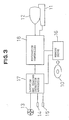
- the self-contained navigational system comprises a console 11, a display 12, a magnetic sensor 13, a distance sensor 14, an angular-velocity sensor 15, a road map memory 10 for storing map data and the like, and a memory drive 16 for reading data from the road map memory 10.
- the self-contained navigational system further comprises a location and heading detecting apparatus 17 which evaluates the probability of existence of a vehicle on each road and calculates the location and heading of the vehicle from the evaluation.
- the self-contained navigational system further comprises a navigation controller 18 which retrieves and reads a predetermined range of a road map, drives the display 18 and performs various arithmetic controls such as controls of the location and heading detecting apparatus 17.
- the above described console 11 has a keyboard (not shown) which allows a vehicle operator to start and stop this self-contained navigational system, and to move a cursor on the picture screen of the display 1 and to scroll the road map displayed on the picture screen.
- the road map memory 10 comprises a mass storage medium memory such as a CDROM, magnetic tape and like.
- the road map is divided into mesh blocks, and data (map data) of route junctions (nodes) to detect a vehicle location at the unit of each mesh block are stored. This road map data are used for graphic display and route calculation.
- the display 12 comprises a CRT (cathode Ray Tube) and a crystalline panel, and displays textual and line graphic information such as road maps, vehicle location, recommended routes, vehicle heading and distance to an destination.
- CTR cathode Ray Tube
- crystalline panel displays textual and line graphic information such as road maps, vehicle location, recommended routes, vehicle heading and distance to an destination.
- the magnetic sensor 13 detects an absolute angle of the heading of the vehicle as it moves over streets.
- the angular-velocity sensor 15 comprises an optical fiber gyro, but it may comprise a vibration gyro or a mechanical type gyro.
- the distance sensor 14 is used to detect distances travelled by the vehicle.
- the distance sensor 14 can constitute a vehicle speed sensor which senses the speed of the vehicle, or one or more wheel sensors which sense the rotation of the wheels of the vehicle.
- the navigation controller 18 receives information about vehicle locations from the location and heading detecting apparatus 17, and displays on the map the current location and destination of the vehicle. More specifically, the navigation controller 18 is constituted by a microcomputer (not shown), a graphic data processor (not shown) and a picture image processing memory (not shown), and performs the display of menus, retrieval of maps, switching of contraction scale, zoom scroll, display of the current location and heading of a vehicle, display of an destination or guide spots, and display of the heading and distance to an destination.
- a microcomputer not shown
- a graphic data processor not shown
- a picture image processing memory not shown
- the location and heading detecting apparatus 17 integrates the distances detected by the distance sensor 14 and the headings detected by the magnetic sensor 13 and angular-velocity sensor 15, and calculates the location of the vehicle by comparing the integrated data with the map data that has been read by the memory drive 16, and outputs the location and heading of the vehicle.
- Fig. 4 shows the structure of the calibration apparatus of the angular-velocity sensor 15.
- the calibration apparatus comprises angular-velocity detection means 21 for detecting the rotational angular velocity of the angular-velocity sensor 15, and integration means 22 for integrating the angular velocity each unit sampling times to calculate a heading angle and for adding the heading angle to the heading obtained at the previous sampling time to calculate a heading ⁇ r at the current time.
- the calibration apparatus further comprises location and heading detection means 23, heading-error-amount count means 24, initial-heading set means 25, and drift calibration means 26.
- the location and heading detection means 23 calculates repeatedly the similarity between the map data and the estimate location obtained from the heading output of the magnetic sensor 13 and distance output of the distance sensor 14, and determines a most probable vehicle location and heading on the road by map matching.
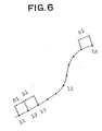
- the heading-error-amount count means 24 compares the heading output ⁇ r from the integration means 22 with the estimated heading output ⁇ e (or heading of the estimated road) from the location and heading detection means 23, at intervals of unit travel distances ⁇ l show in Fig. 6. If the accumulation of the difference between the heading output ⁇ r and the estimated heading output ⁇ e is above a predetermined value, then the heading-error-amount count means 24 feeds a heading correcting output back to the integration means 22.
- the initial-heading set means 25 sets an initial heading ⁇ o of a vehicle with the aid of the magnetic sensor output or heading of the road, when the vehicle starts travelling.
- the drift calibration means 26 calibrates an angular-velocity drift error of the angular-velocity sensor 15.
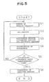
- the output d ⁇ r/dt of the angular-velocity detection means 21 is calculated in step S1, and integrated in step S2 at intervals of predetermined clock times ⁇ t.
- the integrated output is added to the previous heading ⁇ r′ (initial heading is ⁇ o) to obtain the following present heading ⁇ r:
- step S5 it is determined if ⁇ j(n) is above the predetermined value. If yes, an error to one interval of travel distance ⁇ l is calculated by the following equation: The error is subtracted from the heading ⁇ r that has been obtained by the integration means 22. This heading ( ⁇ r - ⁇ j(n)/n) is supplied as ⁇ r to the location and heading detection means 23, and the map matching is continued. If, on the other hand, ⁇ j(n) is not above the predetermined value, the step S5 then returns back to the step S1, and the above described accumulation is repeated.
- the angular-velocity sensor 15 can be calibrated so that a correct heading is obtained at all times.
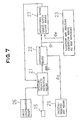
- Fig. 7 shows a second embodiment of the calibration apparatus of the angular-velocity sensor according to the present invention.
- this embodiment is identical to the embodiment of Fig. 4, except that a rotational angle error-ratio count means 27 is provided instead of the heading-error-amount count means 24 and that the output of the rotational angle error-ratio count means 27 is fed back to the angular-velocity detection means 21.
- the rotational angle error-ratio count means 27 detects that the vehicle heading is rotated above a predetermined angle, then it calculates the following ratio: where
- the above described ratio is accumulated each time the angle above a predetermined value is detected. If the accumulated ratio becomes above the predetermined value, then it is fed back to the angular-velocity detection means 21 as a scale factor correcting output.
- the output d ⁇ r/dt of the angular-velocity detection means 21 is calculated in step S11, and integrated in step S12 at intervals of predetermined clock times ⁇ t.
- the integrated output is added to the previous heading ⁇ r′ (initial heading is ⁇ o) to calculate the following present heading ⁇ r:
- step S13 rotational angles ⁇ r(t - 1) and ⁇ e(t - 1) at the time the beginning of one curve in a road has been detected are obtained.
- the beginning of the curve can be detected, for example, by detecting that the output d ⁇ r/dt of the angular-velocity detection means 21 or the differentiated value d2 ⁇ r/dt2 is above a threshold.
- Rotational angles ⁇ r(t) and ⁇ e(t) at the time the end of the curve has been detected are also obtained.
- the end of the curve can be detected, for example, by detecting that the output d ⁇ r/dt of the angular-velocity detection means 21 or the differentiated value d2 ⁇ r/dt2 is below the threshold.
- step S14 the calculation of the ratio is repeated each time the vehicle travels each curve, and accumulated by the following equation:
- step S15 it is determined if ⁇ (m) is above a predetermined value. If yes, the step S15 advances to step 16, in which the scale factor is corrected.
- the scale factor is corrected by dividing d ⁇ r/dt by the following equation: where ⁇ (m)/m is an average value of ⁇ (m) to one curve.
- the scale factor may also be corrected by subtracting a value obtained by multiplying d ⁇ r/dt by ⁇ (m)/m, from d ⁇ r/dt. When ⁇ (m)/m is far below 1, the result of the former computation is nearly the same as that of the latter computation.
- the fluctuation can be automatically calibrated by matching with the rotational angle obtained from the map matching each time the vehicles travels a curve in a road.
- the present invention is not limited to the above described first and second embodiments.
- the effect of the calibration is further enhanced.
Landscapes
- Engineering & Computer Science (AREA)
- Radar, Positioning & Navigation (AREA)
- Remote Sensing (AREA)
- Physics & Mathematics (AREA)
- General Physics & Mathematics (AREA)
- Automation & Control Theory (AREA)
- Navigation (AREA)
- Gyroscopes (AREA)
Priority Applications (1)
| Application Number | Priority Date | Filing Date | Title |
|---|---|---|---|
| EP94102845A EP0602013B1 (fr) | 1989-04-07 | 1990-04-03 | Appareil de calibrage d'un capteur de vitesse angulaire d'un système de navigation autonome |
Applications Claiming Priority (2)
| Application Number | Priority Date | Filing Date | Title |
|---|---|---|---|
| JP88440/89 | 1989-04-07 | ||
| JP1088440A JP2669889B2 (ja) | 1989-04-07 | 1989-04-07 | 自立航法装置に用いる角速度センサの較正装置 |
Related Child Applications (2)
| Application Number | Title | Priority Date | Filing Date |
|---|---|---|---|
| EP94102845A Division EP0602013B1 (fr) | 1989-04-07 | 1990-04-03 | Appareil de calibrage d'un capteur de vitesse angulaire d'un système de navigation autonome |
| EP94102845.8 Division-Into | 1994-02-25 |
Publications (3)
| Publication Number | Publication Date |
|---|---|
| EP0391647A2 true EP0391647A2 (fr) | 1990-10-10 |
| EP0391647A3 EP0391647A3 (fr) | 1992-02-05 |
| EP0391647B1 EP0391647B1 (fr) | 1997-07-30 |
Family
ID=13942861
Family Applications (2)
| Application Number | Title | Priority Date | Filing Date |
|---|---|---|---|
| EP90303527A Expired - Lifetime EP0391647B1 (fr) | 1989-04-07 | 1990-04-03 | Appareil de calibration d'un capteur de vitesse angulaire d'un système de navigation autonome |
| EP94102845A Expired - Lifetime EP0602013B1 (fr) | 1989-04-07 | 1990-04-03 | Appareil de calibrage d'un capteur de vitesse angulaire d'un système de navigation autonome |
Family Applications After (1)
| Application Number | Title | Priority Date | Filing Date |
|---|---|---|---|
| EP94102845A Expired - Lifetime EP0602013B1 (fr) | 1989-04-07 | 1990-04-03 | Appareil de calibrage d'un capteur de vitesse angulaire d'un système de navigation autonome |
Country Status (4)
| Country | Link |
|---|---|
| US (1) | US5115238A (fr) |
| EP (2) | EP0391647B1 (fr) |
| JP (1) | JP2669889B2 (fr) |
| DE (2) | DE69031140T2 (fr) |
Cited By (15)
| Publication number | Priority date | Publication date | Assignee | Title |
|---|---|---|---|---|
| EP0486354A1 (fr) * | 1990-11-16 | 1992-05-20 | Regie Nationale Des Usines Renault S.A. | Procédé et dispositif de positionnement d'un véhicule avec recalage de l'angle de cap relatif |
| EP0496538A2 (fr) * | 1991-01-23 | 1992-07-29 | Sumitomo Electric Industries, Limited | Appareil correcteur d'attitude d'un véhicule |
| EP0747668A2 (fr) * | 1995-06-09 | 1996-12-11 | Xanavi Informatics Corporation | Système pour calculer la position réelle pour véhicule ayant une fonction pour corriger une direction de véhicule |
| EP0747669A2 (fr) * | 1995-06-09 | 1996-12-11 | Xanavi Informatics Corporation | Dispositif pour calculer la position actuelle |
| GB2340611A (en) * | 1998-08-11 | 2000-02-23 | Visteon Tech Llc | Determination of zero angular velocity output level for angular velocity sensor |
| DE19945123A1 (de) * | 1999-09-21 | 2001-04-12 | Mannesmann Vdo Ag | Verfahren zum Navigieren eines Fahrzeugs |
| US7174262B2 (en) | 2004-07-27 | 2007-02-06 | Switched Reluctance Drives Limited | Rotor position detection in an electrical machine |
| US7233873B2 (en) | 2004-07-27 | 2007-06-19 | Switched Reluctance Drives Limited | Rotor position detection in an electrical machine |
| US7370508B2 (en) | 2004-07-06 | 2008-05-13 | Switched Reluctance Drives Limited | Rotor position detection in an electrical machine |
| US20090205401A1 (en) * | 2008-02-16 | 2009-08-20 | Tobias Munko | Method and apparatus for calibrating wheel speeds |
| US7640128B2 (en) | 2004-07-06 | 2009-12-29 | Switched Reluctance Drives Limited | Rotor position detection in an electrical machine |
| CN104682786A (zh) * | 2013-11-27 | 2015-06-03 | 罗伯特·博世有限公司 | 用于确定电机的转子的位置数据的方法和装置 |
| EP2437132B1 (fr) * | 2010-09-30 | 2016-08-17 | Honda Motor Co., Ltd. | Appareil de contrôle pour véhicule à fonctionnement autonome |
| CN111207760A (zh) * | 2019-12-31 | 2020-05-29 | 上海炬宏信息技术有限公司 | 一种路口实时轨迹修正的方法、装置、电子设备及计算机可读介质 |
| EP3561627A4 (fr) * | 2016-12-15 | 2020-07-22 | Positec Power Tools (Suzhou) Co., Ltd | Procédé et dispositif de partitionnement d'une zone de travail d'un appareil automoteur, et dispositif électronique |
Families Citing this family (40)
| Publication number | Priority date | Publication date | Assignee | Title |
|---|---|---|---|---|
| JPH0399217A (ja) * | 1989-09-12 | 1991-04-24 | Sony Corp | 車載用ナビゲーション装置 |
| JPH03279809A (ja) * | 1990-03-28 | 1991-12-11 | Sumitomo Electric Ind Ltd | 方位検出装置 |
| JP2874348B2 (ja) * | 1991-01-10 | 1999-03-24 | 住友電気工業株式会社 | ジャイロのバイアス補正装置 |
| JPH04238221A (ja) * | 1991-01-21 | 1992-08-26 | Sumitomo Electric Ind Ltd | 方位検出装置 |
| JPH0571964A (ja) * | 1991-09-10 | 1993-03-23 | Pioneer Electron Corp | 車両方位検出装置 |
| JPH05157572A (ja) * | 1991-12-10 | 1993-06-22 | Pioneer Electron Corp | ナビゲーション装置 |
| US5424953A (en) * | 1992-01-16 | 1995-06-13 | Pioneer Electronic Corporation | Navigation apparatus |
| JPH0694734A (ja) * | 1992-03-23 | 1994-04-08 | Taya Eng Kk | 角速度検出センサーにおけるドリフトキャンセル方式およびその装置 |
| EP0716315A1 (fr) * | 1992-04-20 | 1996-06-12 | Sumitomo Electric Industries, Ltd. | Dispositif pour corriger le cap d'un véhicule |
| KR0161030B1 (ko) * | 1993-08-26 | 1998-12-15 | 김광호 | 로보트의 구동제어장치 및 그 제어방법 |
| US5742925A (en) * | 1995-05-08 | 1998-04-21 | Pioneer Electronic Corporation | Automotive navigation system |
| US5752220A (en) * | 1995-12-26 | 1998-05-12 | Motorola, Inc. | Method for heading error suppression in dead reckoning systems |
| US5764014A (en) * | 1996-02-01 | 1998-06-09 | Mannesmann Dematic Rapistan Corp. | Automated guided vehicle having ground track sensor |
| JP3591130B2 (ja) * | 1996-05-20 | 2004-11-17 | 松下電器産業株式会社 | ナビゲーション装置 |
| JPH10188463A (ja) * | 1996-12-12 | 1998-07-21 | Samsung Electron Co Ltd | ディスク形記憶装置 |
| US6212455B1 (en) | 1998-12-03 | 2001-04-03 | Indiana Mills & Manufacturing, Inc. | Roll sensor system for a vehicle |
| DE19962997B4 (de) * | 1999-12-24 | 2010-06-02 | Robert Bosch Gmbh | Verfahren zur Kalibrierung eines Sensorsystems |
| US20020022924A1 (en) * | 2000-03-07 | 2002-02-21 | Begin John David | Propagation of position with multiaxis accelerometer |
| EP1236620B1 (fr) | 2001-03-01 | 2007-01-24 | Automotive Systems Laboratory Inc. | Système de détection de tonneau pour véhicule |
| US6600985B2 (en) | 2001-03-26 | 2003-07-29 | Indiana Mills & Manufacturing, Inc. | Roll sensor system for a vehicle |
| JP2002333321A (ja) * | 2001-05-07 | 2002-11-22 | Pioneer Electronic Corp | 角速度検出方法及び装置、角度検出方法及び装置、ナビゲーションシステム及びコンピュータプログラム |
| JP4417583B2 (ja) * | 2001-05-08 | 2010-02-17 | パイオニア株式会社 | ナビゲーション装置 |
| US6597987B1 (en) * | 2001-05-15 | 2003-07-22 | Navigation Technologies Corp. | Method for improving vehicle positioning in a navigation system |
| CN101115646B (zh) * | 2002-03-19 | 2011-11-16 | 汽车系统实验室公司 | 车辆倾翻检测系统 |
| AU2003220396A1 (en) * | 2002-03-19 | 2003-10-08 | Automotive Systems Laboratory, Inc. | Vehicle rollover detection system |
| US6842991B2 (en) * | 2002-07-31 | 2005-01-18 | Robert W. Levi | Gyro aided magnetic compass |
| US6813582B2 (en) * | 2002-07-31 | 2004-11-02 | Point Research Corporation | Navigation device for personnel on foot |
| US7103471B2 (en) | 2002-09-20 | 2006-09-05 | Honeywell International Inc. | Multi-mode navigation device and method |
| KR100626539B1 (ko) * | 2004-08-17 | 2006-09-20 | 엘지전자 주식회사 | 네비게이션 시스템에서 이동체의 방위각 보정방법 |
| JP4520870B2 (ja) * | 2005-01-27 | 2010-08-11 | クラリオン株式会社 | ナビゲーション装置および現在位置表示方法 |
| DE102007041121B4 (de) * | 2007-08-30 | 2022-05-19 | Volkswagen Ag | Verfahren und Vorrichtung zum Verarbeiten von Sensordaten für ein Fahrerassistenzsystem eines Fahrzeugs |
| DE102008002664B4 (de) | 2008-06-26 | 2023-02-02 | Robert Bosch Gmbh | Verfahren und Vorrichtung zum Kalibrieren eines Gierratensensors eines Kraftfahrzeugs |
| US20110087450A1 (en) * | 2009-04-03 | 2011-04-14 | University Of Michigan | Heading Error Removal System for Tracking Devices |
| US20100256939A1 (en) * | 2009-04-03 | 2010-10-07 | The Regents Of The University Of Michigan | Heading Error Removal System for Tracking Devices |
| JP2011145159A (ja) * | 2010-01-14 | 2011-07-28 | Denso Corp | 道路学習装置 |
| DE102010031351A1 (de) * | 2010-07-14 | 2012-01-19 | Bayerische Motoren Werke Aktiengesellschaft | Verfahren und Vorrichtung zum Ermitteln einer Position eines Fahrzeugs |
| JP5420510B2 (ja) * | 2010-09-30 | 2014-02-19 | 本田技研工業株式会社 | 自律走行作業車の制御装置 |
| DE102011006427A1 (de) * | 2011-03-30 | 2012-10-04 | Robert Bosch Gmbh | Drehratensensor und Verfahren zur Kalibrierung eines Drehratensensors |
| JP6901584B2 (ja) * | 2017-11-01 | 2021-07-14 | 日立Astemo株式会社 | 移動体の姿勢センサ装置 |
| DE102022109810A1 (de) | 2022-04-22 | 2023-10-26 | Bayerische Motoren Werke Aktiengesellschaft | Verfahren, Verarbeitungseinrichtung und Computerprogramm zum Steuern einer Fahrzeugfunktion und System für ein Fahrzeug |
Citations (6)
| Publication number | Priority date | Publication date | Assignee | Title |
|---|---|---|---|---|
| EP0166547A2 (fr) * | 1984-06-07 | 1986-01-02 | Etak, Inc. | Dispositif de navigation pour véhicules |
| DE3434896A1 (de) * | 1984-09-22 | 1986-04-03 | Teldix Gmbh, 6900 Heidelberg | Navigationsverfahren |
| JPS6176909A (ja) * | 1984-09-21 | 1986-04-19 | Nissan Motor Co Ltd | 車両用走行位置表示装置 |
| JPS63311116A (ja) * | 1987-06-15 | 1988-12-19 | Tokyo Keiki Co Ltd | 位置検出装置 |
| US4792907A (en) * | 1986-11-17 | 1988-12-20 | Nippondenso Co., Ltd. | Vehicle navigation system |
| EP0302736A1 (fr) * | 1987-08-07 | 1989-02-08 | Honda Giken Kogyo Kabushiki Kaisha | Dispositif pour l'affichage d'un trajet |
Family Cites Families (4)
| Publication number | Priority date | Publication date | Assignee | Title |
|---|---|---|---|---|
| US4470124A (en) * | 1981-06-01 | 1984-09-04 | Honda Giken Kogyo Kabushiki Kaisha | Method of adjusting the zero-point of rate type sensor |
| US4890233A (en) * | 1986-10-27 | 1989-12-26 | Pioneer Electronic Corporation | Vehicle bearing detection and data processing methods applicable to vehicle navigation system |
| JPS63150617A (ja) * | 1986-12-15 | 1988-06-23 | Honda Motor Co Ltd | 走行経路表示装置 |
| JP2584297B2 (ja) * | 1988-10-19 | 1997-02-26 | 本田技研工業株式会社 | 走行経路表示装置 |
-
1989
- 1989-04-07 JP JP1088440A patent/JP2669889B2/ja not_active Expired - Fee Related
-
1990
- 1990-04-02 US US07/502,551 patent/US5115238A/en not_active Expired - Lifetime
- 1990-04-03 DE DE69031140T patent/DE69031140T2/de not_active Expired - Fee Related
- 1990-04-03 DE DE69031283T patent/DE69031283T2/de not_active Expired - Fee Related
- 1990-04-03 EP EP90303527A patent/EP0391647B1/fr not_active Expired - Lifetime
- 1990-04-03 EP EP94102845A patent/EP0602013B1/fr not_active Expired - Lifetime
Patent Citations (6)
| Publication number | Priority date | Publication date | Assignee | Title |
|---|---|---|---|---|
| EP0166547A2 (fr) * | 1984-06-07 | 1986-01-02 | Etak, Inc. | Dispositif de navigation pour véhicules |
| JPS6176909A (ja) * | 1984-09-21 | 1986-04-19 | Nissan Motor Co Ltd | 車両用走行位置表示装置 |
| DE3434896A1 (de) * | 1984-09-22 | 1986-04-03 | Teldix Gmbh, 6900 Heidelberg | Navigationsverfahren |
| US4792907A (en) * | 1986-11-17 | 1988-12-20 | Nippondenso Co., Ltd. | Vehicle navigation system |
| JPS63311116A (ja) * | 1987-06-15 | 1988-12-19 | Tokyo Keiki Co Ltd | 位置検出装置 |
| EP0302736A1 (fr) * | 1987-08-07 | 1989-02-08 | Honda Giken Kogyo Kabushiki Kaisha | Dispositif pour l'affichage d'un trajet |
Non-Patent Citations (2)
| Title |
|---|
| PATENT ABSTRACTS OF JAPAN vol. 10, no. 247 (P-490)(2303) 26 August 1986 & JP-A-61 076 909 ( NISSAN MOTOR CO LTD ) 19 April 1986 * |
| PATENT ABSTRACTS OF JAPAN vol. 13, no. 149 (P-855)(3497) 12 April 1989 & JP-A-63 311 116 ( TOKYO KEIKI CO LTD ) 19 December 1988 * |
Cited By (29)
| Publication number | Priority date | Publication date | Assignee | Title |
|---|---|---|---|---|
| EP0486354A1 (fr) * | 1990-11-16 | 1992-05-20 | Regie Nationale Des Usines Renault S.A. | Procédé et dispositif de positionnement d'un véhicule avec recalage de l'angle de cap relatif |
| FR2669435A1 (fr) * | 1990-11-16 | 1992-05-22 | Renault | Procede et dispositif de positionnement d'un vehicule avec recalage de l'angle de cap relatif. |
| EP0496538A2 (fr) * | 1991-01-23 | 1992-07-29 | Sumitomo Electric Industries, Limited | Appareil correcteur d'attitude d'un véhicule |
| EP0496538A3 (en) * | 1991-01-23 | 1992-12-23 | Sumitomo Electric Industries, Limited | Vehicle heading correction apparatus |
| US5317515A (en) * | 1991-01-23 | 1994-05-31 | Sumitomo Electric Industries, Ltd. | Vehicle heading correction apparatus |
| EP0747669A2 (fr) * | 1995-06-09 | 1996-12-11 | Xanavi Informatics Corporation | Dispositif pour calculer la position actuelle |
| EP0747669A3 (fr) * | 1995-06-09 | 1998-02-25 | Xanavi Informatics Corporation | Dispositif pour calculer la position actuelle |
| EP0747668A3 (fr) * | 1995-06-09 | 1998-02-25 | Xanavi Informatics Corporation | Système pour calculer la position réelle pour véhicule ayant une fonction pour corriger une direction de véhicule |
| US5839087A (en) * | 1995-06-09 | 1998-11-17 | Zanavy Informatics Kk | Current position calculating system for a vehicle having a function for correcting a vehicle direction |
| US5941934A (en) * | 1995-06-09 | 1999-08-24 | Xanavi Informatics Corporation | Current position calculating device |
| EP1288623A1 (fr) * | 1995-06-09 | 2003-03-05 | Xanavi Informatics Corporation | Dispositif pour calculer la position actuelle |
| EP0747668A2 (fr) * | 1995-06-09 | 1996-12-11 | Xanavi Informatics Corporation | Système pour calculer la position réelle pour véhicule ayant une fonction pour corriger une direction de véhicule |
| GB2340611B (en) * | 1998-08-11 | 2002-06-26 | Visteon Tech Llc | Determination of zero-angular-velocity output level for angular velocity sensor |
| GB2340611A (en) * | 1998-08-11 | 2000-02-23 | Visteon Tech Llc | Determination of zero angular velocity output level for angular velocity sensor |
| US6147626A (en) * | 1998-08-11 | 2000-11-14 | Visteon Technologies, Llc | Determination of zero-angular-velocity output level for angular velocity sensor |
| DE19945123C2 (de) * | 1999-09-21 | 2001-12-13 | Mannesmann Vdo Ag | Verfahren zum Navigieren eines Fahrzeugs |
| DE19945123A1 (de) * | 1999-09-21 | 2001-04-12 | Mannesmann Vdo Ag | Verfahren zum Navigieren eines Fahrzeugs |
| US7640128B2 (en) | 2004-07-06 | 2009-12-29 | Switched Reluctance Drives Limited | Rotor position detection in an electrical machine |
| US7370508B2 (en) | 2004-07-06 | 2008-05-13 | Switched Reluctance Drives Limited | Rotor position detection in an electrical machine |
| US7174262B2 (en) | 2004-07-27 | 2007-02-06 | Switched Reluctance Drives Limited | Rotor position detection in an electrical machine |
| US7233873B2 (en) | 2004-07-27 | 2007-06-19 | Switched Reluctance Drives Limited | Rotor position detection in an electrical machine |
| US8336364B2 (en) * | 2008-02-16 | 2012-12-25 | Wabco Gmbh | Method and apparatus for calibrating wheel speeds |
| US20090205401A1 (en) * | 2008-02-16 | 2009-08-20 | Tobias Munko | Method and apparatus for calibrating wheel speeds |
| EP2437132B1 (fr) * | 2010-09-30 | 2016-08-17 | Honda Motor Co., Ltd. | Appareil de contrôle pour véhicule à fonctionnement autonome |
| CN104682786A (zh) * | 2013-11-27 | 2015-06-03 | 罗伯特·博世有限公司 | 用于确定电机的转子的位置数据的方法和装置 |
| CN104682786B (zh) * | 2013-11-27 | 2019-03-05 | 罗伯特·博世有限公司 | 用于确定电机的转子的位置数据的方法和装置 |
| EP3561627A4 (fr) * | 2016-12-15 | 2020-07-22 | Positec Power Tools (Suzhou) Co., Ltd | Procédé et dispositif de partitionnement d'une zone de travail d'un appareil automoteur, et dispositif électronique |
| CN111207760A (zh) * | 2019-12-31 | 2020-05-29 | 上海炬宏信息技术有限公司 | 一种路口实时轨迹修正的方法、装置、电子设备及计算机可读介质 |
| CN111207760B (zh) * | 2019-12-31 | 2022-03-22 | 上海炬宏信息技术有限公司 | 一种路口实时轨迹修正的方法、装置、电子设备及计算机可读介质 |
Also Published As
| Publication number | Publication date |
|---|---|
| EP0602013A3 (en) | 1994-08-17 |
| DE69031283T2 (de) | 1998-02-05 |
| DE69031283D1 (de) | 1997-09-18 |
| JP2669889B2 (ja) | 1997-10-29 |
| DE69031140T2 (de) | 1998-03-05 |
| JPH02266221A (ja) | 1990-10-31 |
| EP0391647B1 (fr) | 1997-07-30 |
| US5115238A (en) | 1992-05-19 |
| DE69031140D1 (de) | 1997-09-04 |
| EP0602013B1 (fr) | 1997-08-13 |
| EP0602013A2 (fr) | 1994-06-15 |
| EP0391647A3 (fr) | 1992-02-05 |
Similar Documents
| Publication | Publication Date | Title |
|---|---|---|
| US5115238A (en) | Calibration apparatus of angular velocity sensor in self-contained navigational system | |
| EP0607654B1 (fr) | Méthode pour la correction de l'erreur de distance dans un système de navigation | |
| US5119301A (en) | Vehicle location detecting system | |
| EP0488594B1 (fr) | Dispositif de correction de décalage d'un capteur de vitesse de braquage | |
| US7640102B2 (en) | Self-tuning apparatus of vehicle speed pulse coefficient and method thereof | |
| EP0555586B1 (fr) | Correction de point zéro pour gyroscope | |
| EP0678228B1 (fr) | Procede et dispositif de correction de la position destine a un systeme de navigation de vehicule | |
| EP0566391B1 (fr) | Dispositif pour déterminer la position d'un véhicule | |
| EP0566390B1 (fr) | Dispositif pour déterminer la position d'un véhicule | |
| EP0496172B1 (fr) | Appareil de correction de point zéro d'un gyroscope | |
| EP0453726A2 (fr) | Appareil pour la navigation d'un véhicule | |
| US6766247B2 (en) | Position determination method and navigation device | |
| US5367898A (en) | Method of calculating scale factor of gyro | |
| JP2001522986A (ja) | 車両のナビゲーション装置 | |
| JPH0833302B2 (ja) | 位置検出装置 | |
| WO2000050917A1 (fr) | Systeme de navigation pour vehicule avec correction de disponibilite selective | |
| JPH0735558A (ja) | 車両の現在位置検出装置 | |
| JP3012501B2 (ja) | 車両位置検出装置 | |
| EP0564140B1 (fr) | Dispositif de localisation de véhicule | |
| JP3082293B2 (ja) | ナビゲーション装置 | |
| JP3545798B2 (ja) | 現在位置算出装置 | |
| JPH06147908A (ja) | ナビゲーション装置 | |
| JPH0446368B2 (fr) | ||
| JPH04346024A (ja) | 方位検出方法および方位検出装置 | |
| JPH04346023A (ja) | 方位検出方法および方位検出装置 |
Legal Events
| Date | Code | Title | Description |
|---|---|---|---|
| PUAI | Public reference made under article 153(3) epc to a published international application that has entered the european phase |
Free format text: ORIGINAL CODE: 0009012 |
|
| AK | Designated contracting states |
Kind code of ref document: A2 Designated state(s): DE FR GB |
|
| PUAL | Search report despatched |
Free format text: ORIGINAL CODE: 0009013 |
|
| AK | Designated contracting states |
Kind code of ref document: A3 Designated state(s): DE FR GB |
|
| 17P | Request for examination filed |
Effective date: 19920316 |
|
| 17Q | First examination report despatched |
Effective date: 19930419 |
|
| GRAG | Despatch of communication of intention to grant |
Free format text: ORIGINAL CODE: EPIDOS AGRA |
|
| GRAH | Despatch of communication of intention to grant a patent |
Free format text: ORIGINAL CODE: EPIDOS IGRA |
|
| GRAH | Despatch of communication of intention to grant a patent |
Free format text: ORIGINAL CODE: EPIDOS IGRA |
|
| GRAH | Despatch of communication of intention to grant a patent |
Free format text: ORIGINAL CODE: EPIDOS IGRA |
|
| GRAA | (expected) grant |
Free format text: ORIGINAL CODE: 0009210 |
|
| AK | Designated contracting states |
Kind code of ref document: B1 Designated state(s): DE FR GB |
|
| XX | Miscellaneous (additional remarks) |
Free format text: TEILANMELDUNG 94102845.8 EINGEREICHT AM 03/04/90. |
|
| REF | Corresponds to: |
Ref document number: 69031140 Country of ref document: DE Date of ref document: 19970904 |
|
| ET | Fr: translation filed | ||
| PLBE | No opposition filed within time limit |
Free format text: ORIGINAL CODE: 0009261 |
|
| STAA | Information on the status of an ep patent application or granted ep patent |
Free format text: STATUS: NO OPPOSITION FILED WITHIN TIME LIMIT |
|
| 26N | No opposition filed | ||
| REG | Reference to a national code |
Ref country code: GB Ref legal event code: IF02 |
|
| PGFP | Annual fee paid to national office [announced via postgrant information from national office to epo] |
Ref country code: GB Payment date: 20040331 Year of fee payment: 15 |
|
| PGFP | Annual fee paid to national office [announced via postgrant information from national office to epo] |
Ref country code: FR Payment date: 20040408 Year of fee payment: 15 |
|
| PGFP | Annual fee paid to national office [announced via postgrant information from national office to epo] |
Ref country code: DE Payment date: 20040415 Year of fee payment: 15 |
|
| PG25 | Lapsed in a contracting state [announced via postgrant information from national office to epo] |
Ref country code: GB Free format text: LAPSE BECAUSE OF NON-PAYMENT OF DUE FEES Effective date: 20050403 |
|
| PG25 | Lapsed in a contracting state [announced via postgrant information from national office to epo] |
Ref country code: DE Free format text: LAPSE BECAUSE OF NON-PAYMENT OF DUE FEES Effective date: 20051101 |
|
| GBPC | Gb: european patent ceased through non-payment of renewal fee |
Effective date: 20050403 |
|
| PG25 | Lapsed in a contracting state [announced via postgrant information from national office to epo] |
Ref country code: FR Free format text: LAPSE BECAUSE OF NON-PAYMENT OF DUE FEES Effective date: 20051230 |
|
| REG | Reference to a national code |
Ref country code: FR Ref legal event code: ST Effective date: 20051230 |