EP0389262A2 - Procédé de contrôle d'une transmission à réglage continu et étrangleur - Google Patents
Procédé de contrôle d'une transmission à réglage continu et étrangleur Download PDFInfo
- Publication number
- EP0389262A2 EP0389262A2 EP90303039A EP90303039A EP0389262A2 EP 0389262 A2 EP0389262 A2 EP 0389262A2 EP 90303039 A EP90303039 A EP 90303039A EP 90303039 A EP90303039 A EP 90303039A EP 0389262 A2 EP0389262 A2 EP 0389262A2
- Authority
- EP
- European Patent Office
- Prior art keywords
- target
- engine
- acceleration
- rotational speed
- engine rotational
- Prior art date
- Legal status (The legal status is an assumption and is not a legal conclusion. Google has not performed a legal analysis and makes no representation as to the accuracy of the status listed.)
- Granted
Links
Images


Classifications
-
- B—PERFORMING OPERATIONS; TRANSPORTING
- B60—VEHICLES IN GENERAL
- B60W—CONJOINT CONTROL OF VEHICLE SUB-UNITS OF DIFFERENT TYPE OR DIFFERENT FUNCTION; CONTROL SYSTEMS SPECIALLY ADAPTED FOR HYBRID VEHICLES; ROAD VEHICLE DRIVE CONTROL SYSTEMS FOR PURPOSES NOT RELATED TO THE CONTROL OF A PARTICULAR SUB-UNIT
- B60W10/00—Conjoint control of vehicle sub-units of different type or different function
- B60W10/04—Conjoint control of vehicle sub-units of different type or different function including control of propulsion units
- B60W10/06—Conjoint control of vehicle sub-units of different type or different function including control of propulsion units including control of combustion engines
-
- B—PERFORMING OPERATIONS; TRANSPORTING
- B60—VEHICLES IN GENERAL
- B60W—CONJOINT CONTROL OF VEHICLE SUB-UNITS OF DIFFERENT TYPE OR DIFFERENT FUNCTION; CONTROL SYSTEMS SPECIALLY ADAPTED FOR HYBRID VEHICLES; ROAD VEHICLE DRIVE CONTROL SYSTEMS FOR PURPOSES NOT RELATED TO THE CONTROL OF A PARTICULAR SUB-UNIT
- B60W10/00—Conjoint control of vehicle sub-units of different type or different function
- B60W10/04—Conjoint control of vehicle sub-units of different type or different function including control of propulsion units
-
- B—PERFORMING OPERATIONS; TRANSPORTING
- B60—VEHICLES IN GENERAL
- B60W—CONJOINT CONTROL OF VEHICLE SUB-UNITS OF DIFFERENT TYPE OR DIFFERENT FUNCTION; CONTROL SYSTEMS SPECIALLY ADAPTED FOR HYBRID VEHICLES; ROAD VEHICLE DRIVE CONTROL SYSTEMS FOR PURPOSES NOT RELATED TO THE CONTROL OF A PARTICULAR SUB-UNIT
- B60W10/00—Conjoint control of vehicle sub-units of different type or different function
- B60W10/10—Conjoint control of vehicle sub-units of different type or different function including control of change-speed gearings
- B60W10/101—Infinitely variable gearings
- B60W10/103—Infinitely variable gearings of fluid type
-
- B—PERFORMING OPERATIONS; TRANSPORTING
- B60—VEHICLES IN GENERAL
- B60W—CONJOINT CONTROL OF VEHICLE SUB-UNITS OF DIFFERENT TYPE OR DIFFERENT FUNCTION; CONTROL SYSTEMS SPECIALLY ADAPTED FOR HYBRID VEHICLES; ROAD VEHICLE DRIVE CONTROL SYSTEMS FOR PURPOSES NOT RELATED TO THE CONTROL OF A PARTICULAR SUB-UNIT
- B60W30/00—Purposes of road vehicle drive control systems not related to the control of a particular sub-unit, e.g. of systems using conjoint control of vehicle sub-units, or advanced driver assistance systems for ensuring comfort, stability and safety or drive control systems for propelling or retarding the vehicle
- B60W30/18—Propelling the vehicle
- B60W30/1819—Propulsion control with control means using analogue circuits, relays or mechanical links
-
- B—PERFORMING OPERATIONS; TRANSPORTING
- B60—VEHICLES IN GENERAL
- B60W—CONJOINT CONTROL OF VEHICLE SUB-UNITS OF DIFFERENT TYPE OR DIFFERENT FUNCTION; CONTROL SYSTEMS SPECIALLY ADAPTED FOR HYBRID VEHICLES; ROAD VEHICLE DRIVE CONTROL SYSTEMS FOR PURPOSES NOT RELATED TO THE CONTROL OF A PARTICULAR SUB-UNIT
- B60W30/00—Purposes of road vehicle drive control systems not related to the control of a particular sub-unit, e.g. of systems using conjoint control of vehicle sub-units, or advanced driver assistance systems for ensuring comfort, stability and safety or drive control systems for propelling or retarding the vehicle
- B60W30/18—Propelling the vehicle
- B60W30/188—Controlling power parameters of the driveline, e.g. determining the required power
- B60W30/1882—Controlling power parameters of the driveline, e.g. determining the required power characterised by the working point of the engine, e.g. by using engine output chart
-
- F—MECHANICAL ENGINEERING; LIGHTING; HEATING; WEAPONS; BLASTING
- F16—ENGINEERING ELEMENTS AND UNITS; GENERAL MEASURES FOR PRODUCING AND MAINTAINING EFFECTIVE FUNCTIONING OF MACHINES OR INSTALLATIONS; THERMAL INSULATION IN GENERAL
- F16H—GEARING
- F16H61/00—Control functions within control units of change-speed- or reversing-gearings for conveying rotary motion ; Control of exclusively fluid gearing, friction gearing, gearings with endless flexible members or other particular types of gearing
- F16H61/38—Control of exclusively fluid gearing
- F16H61/40—Control of exclusively fluid gearing hydrostatic
- F16H61/42—Control of exclusively fluid gearing hydrostatic involving adjustment of a pump or motor with adjustable output or capacity
- F16H61/425—Motor capacity control by electric actuators
-
- F—MECHANICAL ENGINEERING; LIGHTING; HEATING; WEAPONS; BLASTING
- F16—ENGINEERING ELEMENTS AND UNITS; GENERAL MEASURES FOR PRODUCING AND MAINTAINING EFFECTIVE FUNCTIONING OF MACHINES OR INSTALLATIONS; THERMAL INSULATION IN GENERAL
- F16H—GEARING
- F16H61/00—Control functions within control units of change-speed- or reversing-gearings for conveying rotary motion ; Control of exclusively fluid gearing, friction gearing, gearings with endless flexible members or other particular types of gearing
- F16H61/38—Control of exclusively fluid gearing
- F16H61/40—Control of exclusively fluid gearing hydrostatic
- F16H61/46—Automatic regulation in accordance with output requirements
- F16H61/462—Automatic regulation in accordance with output requirements for achieving a target speed ratio
-
- F—MECHANICAL ENGINEERING; LIGHTING; HEATING; WEAPONS; BLASTING
- F16—ENGINEERING ELEMENTS AND UNITS; GENERAL MEASURES FOR PRODUCING AND MAINTAINING EFFECTIVE FUNCTIONING OF MACHINES OR INSTALLATIONS; THERMAL INSULATION IN GENERAL
- F16H—GEARING
- F16H61/00—Control functions within control units of change-speed- or reversing-gearings for conveying rotary motion ; Control of exclusively fluid gearing, friction gearing, gearings with endless flexible members or other particular types of gearing
- F16H61/38—Control of exclusively fluid gearing
- F16H61/40—Control of exclusively fluid gearing hydrostatic
- F16H61/46—Automatic regulation in accordance with output requirements
- F16H61/47—Automatic regulation in accordance with output requirements for achieving a target output speed
-
- F—MECHANICAL ENGINEERING; LIGHTING; HEATING; WEAPONS; BLASTING
- F16—ENGINEERING ELEMENTS AND UNITS; GENERAL MEASURES FOR PRODUCING AND MAINTAINING EFFECTIVE FUNCTIONING OF MACHINES OR INSTALLATIONS; THERMAL INSULATION IN GENERAL
- F16H—GEARING
- F16H61/00—Control functions within control units of change-speed- or reversing-gearings for conveying rotary motion ; Control of exclusively fluid gearing, friction gearing, gearings with endless flexible members or other particular types of gearing
- F16H61/66—Control functions within control units of change-speed- or reversing-gearings for conveying rotary motion ; Control of exclusively fluid gearing, friction gearing, gearings with endless flexible members or other particular types of gearing specially adapted for continuously variable gearings
-
- B—PERFORMING OPERATIONS; TRANSPORTING
- B60—VEHICLES IN GENERAL
- B60W—CONJOINT CONTROL OF VEHICLE SUB-UNITS OF DIFFERENT TYPE OR DIFFERENT FUNCTION; CONTROL SYSTEMS SPECIALLY ADAPTED FOR HYBRID VEHICLES; ROAD VEHICLE DRIVE CONTROL SYSTEMS FOR PURPOSES NOT RELATED TO THE CONTROL OF A PARTICULAR SUB-UNIT
- B60W2720/00—Output or target parameters relating to overall vehicle dynamics
- B60W2720/10—Longitudinal speed
- B60W2720/106—Longitudinal acceleration
-
- F—MECHANICAL ENGINEERING; LIGHTING; HEATING; WEAPONS; BLASTING
- F16—ENGINEERING ELEMENTS AND UNITS; GENERAL MEASURES FOR PRODUCING AND MAINTAINING EFFECTIVE FUNCTIONING OF MACHINES OR INSTALLATIONS; THERMAL INSULATION IN GENERAL
- F16H—GEARING
- F16H59/00—Control inputs to control units of change-speed-, or reversing-gearings for conveying rotary motion
- F16H59/74—Inputs being a function of engine parameters
- F16H2059/743—Inputs being a function of engine parameters using engine performance or power for control of gearing
-
- F—MECHANICAL ENGINEERING; LIGHTING; HEATING; WEAPONS; BLASTING
- F16—ENGINEERING ELEMENTS AND UNITS; GENERAL MEASURES FOR PRODUCING AND MAINTAINING EFFECTIVE FUNCTIONING OF MACHINES OR INSTALLATIONS; THERMAL INSULATION IN GENERAL
- F16H—GEARING
- F16H59/00—Control inputs to control units of change-speed-, or reversing-gearings for conveying rotary motion
- F16H59/36—Inputs being a function of speed
Definitions
- the present invention relates to a method of controlling a continuously variable transmission on a motor vehicle or the like, and more particularly to a method of controlling a continuously variable transmission in combination with the control of the throttle valve of an engine.
- continuously variable transmissions are generally controlled such that (a) the rotational speed of an engine coupled to the continuously variable transmission will reach a target speed, (b) the rate of change of the rotational speed of the engine will reach a target rate, and (c) the speed reduction ratio or transmission ratio of the transmission will reach a target ratio.
- the rate of change of a speed reduction ratio is controlled, the rate being calculated as the sum of a component corresponding to a predicted acceleration that is calculated from a reserved horsepower of an engine coupled to the transmission and a component corresponding to a target rate of change of the engine rotational speed (see, for example, Japanese Laid-Open Patent Publication No. 63-53343 filed by the applicant).
- the reserved power is a power which is available corresponding to the present accelerator opening but is not used. In other word, the engine can afford to output the reserved power under the present accelerator opening.
- the rotational speed of the engine is increased to a speed value corresponding to the depth to which the accelerator pedal is depressed (the amount of depression of the accelerator pedal), and then the motor vehicle is accelerated while the engine rotational speed is being kept constant. Therefore, the rotational speed of the engine or the rate of change of the rotational speed of the engine does not match the motor vehicle acceleration as felt by the driver, and the depression of the accelerator pedal also does not match the motor vehicle acceleration as felt by the driver.
- a target terminal acceleration Go to be reached is established according to an indication of the driver's intention for acceleration or deceleration, such as the amount of depression of the accelerator pedal, and also to an indication of the speed of the motor vehicle, and a present calculative acceleration G CAL is calculated on the basis of a reserved power at the present time of the engine which drives the continuously variable transmission.
- the throttle valve of the engine and the continuously variable transmission are controlled so that the target present acceleration Gon will be reached.
- the acceleration (or deceleration) of the motor vehicle is directly controlled along the desired characteristic curve depending on a change in the indication of the driver's intention for acceleration or deceleration, such as the amount of depression of the accelerator pedal. Therefore, the motor vehicle runs in a manner to meet the demand for acceleration, represented by the depression by the driver of the accelerator pedal. Since the transmission and the throttle valve are controlled using, as a target value, the acceleration (or deceleration) whose changes can be sensed by the driver, the desired characteristic which meets the demand of the driver is reliably achieved.
- the calculative acceleration G CAL which is calculated on the basis of the reserved engine power is employed rather than an acceleration that is obtained on the basis of a measured value indicated by an acceleration sensor, a vehicle speed sensor, or the like. If an acceleration sensor were employed, it would be difficult to accomplish accurate control since the accuracy of the acceleration sensor would be lowered by vibrations of the motor vehicle during travel. Furthermore, in order to perform a transient control mode in which the accelerator pedal is abruptly depressed, for example, each of the control cycles is quite short (e.g., 10 ms).
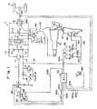
- FIG. 1 shows a hydraulic circuit of a continuously variable transmission which is to be controlled by a control method according to the present invention.
- the continuously variable transmission generally designated by the reference numeral T, has a fixed-displacement hydraulic pump P drivable by an engine E on a motor vehicle through an input shaft 1 and a variable-displacement hydraulic motor M having an output shaft 2 for driving road wheels W of the motor vehicle.
- the hydraulic pump P and the hydraulic motor M are hydraulically connected to each other through a closed hydraulic circuit including a first oil passage La interconnecting the outlet port of the pump P and the inlet port of the motor M and a second oil passage Lb interconnecting the inlet port of the pump P and the outlet port of the motor M.
- a charging pump 10 drivable by the engine E has an outlet port connected to the closed hydraulic circuit through a charging oil passage Lh having check valve 11 and a third oil passage Lc having a pair of check valves 3.
- Working oil supplied from an oil sump 15 by the charging pump 10 and regulated in pressure by a charging pressure relief valve 12 is supplied through one of the check valves 3 to a lower-pressure one of the oil passages La, Lb.
- a fourth oil passage Ld having a shuttle valve 4 coupled to fifth and sixth oil passages Le, Lf having higher- and lower-pressure relief valves 6, 7 and connected to the oil sump 15.
- the shuttle valve 4 which comprises a two-port three-position directional control valve is operable in response to the difference between oil pressures in the first and second oil passages La, Lb for connecting a higher-pressure one of the first and second oil passages La, Lb to the fifth oil passage Le and the lower-pressure oil passage to the sixth oil passage Lf. Therefore, the oil pressure relieved from the higher-pressure oil passage is regulated by the higher-pressure relief valve 6, whereas the oil pressure relieved from the lower-pressure oil passage is regulated by the lower-pressure relief valve 7.
- a seventh oil passage Lg having a clutch valve 5 which comprises a variable restriction controlled by an opening control unit (not shown) for controlling the opening of the seventh oil passage Lg.
- the transmission of the drive power from the hydraulic pump P to the hydraulic motor M can be controlled through the control of the cross-sectional flow area in the clutch valve 5.
- An actuator for controlling the displacement of the hydraulic motor M to control the speed reduction ratio or transmission ratio of the continuously variable transmission T comprises a pair of first and second servovalves 30, 50 mechanically operably coupled to each other by a link mechanism 45.
- the hydraulic motor M comprises a swash-plate axial-piston motor whose displacement can be controlled by controlling the angle of the swash plate thereof.
- the higher-pressure working oil supplied from the closed hydraulic circuit of the continuously variable transmission T through the shuttle valve 4 to the fifth oil passage Le is introduced into the first servovalve 30 through a high-pressure line 120 branched from the fifth oil passage Le.
- the first servovalve 30 controls the swash plate angle of the hydraulic motor M under the higher-pressure working oil thus introduced.
- the second servovalve 50 controls operation of the first servovalve 30 through the link mechanism 45 by which the second servovalve 50 is operatively coupled to the first servovalve 30.
- the first servovalve 30 comprises a housing 31 having a port 31a connected to the high-pressure line 120, a piston member 32 slidably disposed in the housing 31, and a spool member 34 coaxially slidably disposed in the piston 32.
- the piston member 32 has a piston 32a on its righthand (as shown) end, and a cylindrical rod 32b extending coaxially from the piston 32a to the left (as shown).
- the piston 32a is positioned in a cylinder hole 31c defined in the housing 31 and divides the space of the cylinder hole 31c into left and right (as shown) cylinder chambers 35, 36.
- the rod 32b is slidably fitted in a rod hole 31d which is smaller in diameter than and extends coaxially from the cylinder hole 31c.
- the right cylinder chamber 35 is closed by a plug 33a and a cover 33b.
- the spool member 34 extends through the piston 32a,, the right cylinder chamber 36, the plug 33a, and the cover 33b.
- the left cylinder chamber 35 communicates with the high-pressure line 120 through an oil passage 31b defined in the housing 31.
- the piston member 32 can therefore be moved to the right under the oil pressure introduced from the high-pressure line 120 into the left cylinder chamber 35.
- the spool member 34 has on its distal end a land 34a closely fitted in a spool hole 32d defined coaxially in the rod 32b.
- the spool member 34 also has a recess 34b defined on the righthand side of the land 34a by a pair of diametrically opposite cutouts, the recess 34b having a predetermined axial dimension.
- a retaining ring 37 is fitted over the spool member 34 on the righthand side of the recess 34b. The spool member 34 is prevented from removal from the piston member 32 by the retaining ring 37 upon engagement with another retaining ring 38 locked in an inner peripheral surface of the piston member 32.
- the piston member 32 has defined therein a discharge passage 32e for opening the right cylinder chamber 36 into an oil sump (not shown) through the spool hole 32d upon rightward movement of the spool member 34, and a communication passage 32c for bringing the right cylinder chamber 36 into communication with the left cylinder chamber 35 through the recess 34b upon leftward movement of the spool member 34.
- the recess 34b opens the communication passage 32c into the right cylinder chamber 36, and the land 34a closes the discharge passage32e.
- the high-pressure oil from the high-pressure line 120 then acts in both the left and right cylinder chambers 35, 36. Since the piston 32a has different pressure-bearing surface areas on its axially opposite sides, i.e., the righthand pressure-bearing surface area is greater than the lefthand pressure-bearing surface area, the piston 32 is moved to the left in follow-up coaction with the spool member 34.
- the piston member 32 is moved in follow-up unison with the spool member 34 under the pressure of the oil supplied from the high-pressure line 120.
- the piston member 32 then causes a link 39 coupled thereto to turn the swash plate Mt of the hydraulic motor M about a shaft Ms for thereby varying the displacement of the hydraulic motor M.
- the spool member 34 is operatively coupled to the second servovalve 50 by the link mechanism 45.
- the link mechanism 45 comprises a first link 47 rotatable about a shaft 47c and having two substantially perpendicular arms 47a, 47b, and a second link 48 joined by a pin to the lower distal end of the arm 47b of the first link 47.
- the upper end of the arm 47a is connected by a pin to the righthand end of the spool member 34 of the first servovalve 30.
- the lower end of the second link 48 is coupled by a pin to a vertical (as shown) spool member 54 of the second servovalve 50. Consequently, vertical movement of the spool member 54 of the second servovalve 50 causes the spool member 34 of the first servovalve 30 to move to the left or right.
- the second servovalve 50 has a housing 51 having two ports 51a, 51b to which two oil pressure lines 102, 104 are connected, respectively, and the spool member 54 is vertically slidably disposed in the housing 51.
- the spool member 54 comprises a piston 54a and a rod 54b extending coaxially downwardly from the piston 54a.
- the piston 54a is slidably fitted in a cylinder hole 51c defined vertically in the housing 51.
- the cylinder hole 51c closed by a cover 55, defining a cylinder chamber therein which is divided by the piston 54a into upper and lower cylinder chambers 52, 53.
- the rod 54b is slidably fitted in a rod hole 51d which is defined coaxially in the housing 51 and extends downwardly from the cylinder hole 51c.
- the rod 54b has a recess 54e defined in a peripheral surface and having a tapered surface.
- a top position detector switch 58 has a spool 58a projecting into the recess 54e. When the spool member 54 moves upwardly, the spool 58a is lifted in a direction away from the rod 54b as the tip end of the spool 58a slides up the tapered surface. Therefore, the top position detector switch 58 can detect when the transmission ratio of the hydraulic motor M is minimum.
- the upper and lower cylinder chambers 52, 53 defined by the piston 54a communicate respectively with the oil pressure lines 102, 104 through the ports 51a, 51b.
- the spool member 54 is moved upwardly or downwardly depending on the magnitude of an oil pressure applied to the piston 54a, the oil pressure being determined by the pressure of working oil supplied through the lines 102, 104 and the pressure-bearing surface areas of the piston 54a in the cylinder chambers 52, 53.
- the vertical movement of the spool member 54 is transmitted through the link mechanism 45 to the spool member 34 of the first servovalve 30 thereby to move the spool member 34 to the left or right.
- the movement of the spool member 34 of the first servovalve 30 can be controlled to move the piston member 32 for thereby controlling the swash plate angle of the hydraulic motor M, so that the displacement of the motor M will be controlled to control the transmission ratio or speed reduction ratio.
- the piston member 32 of the first servovalve 30 is moved to the right to reduce the swash plate angle of the hydraulic motor M for reducing the displacement of the motor M and hence the speed reduction ratio.
- Oil pressure which is supplied to the upper cylinder chamber 52 through the port 51a from the oil pressure line 102 is introduced from the charging pump 10, while being regulated by the charging pressure relief valve 12, through an oil pressure line 101.
- Oil pressure which is supplied to the lower cylinder chamber 53 through the port 51b is introduced from an oil pressure line 103 branched from the oil pressure line 102 and having an orifice 103a, while being regulated by two duty-ratio-controlled solenoid-operated valves 151, 102, through an oil pressure line 104.
- the solenoid-operated valve 151 is opened and closed depending on a given duty ratio to control the rate of flow of working oil from the oil pressure line 103 to the oil pressure line 104.
- the solenoid-operated valve 152 is connected between an oil pressure line 105 branching from the oil pressure line 104 and an oil pressure line 106 connected to a drain through an orifice 106a.
- the solenoid-operated valve 152 is opened and closed depending on a given duty ratio to control the rate of flow of working oil from the oil pressure line 104 to the drain.
- the upper cylinder chamber 52 is supplied through the oil pressure line 102 with the charging oil pressure which has been regulated by the charging pressure relief valve 12.
- the oil pressure line 104 supplied the lower cylinder chamber 53 with an oil pressure which is made lower than the charging oil pressure by the two solenoid-operated valves 151, 152. Since the pressure-bearing surface area of the upper cylinder chamber 52 is smaller than that of the lower cylinder chamber 53, the forces acting on the opposite sides of the spool member 54 under the oil pressures in the upper and lower cylinder chambers 52, 53 are brought into equilibrium when the oil pressure Pu in the upper cylinder chamber 52 is higher than a certain level Pl of the oil pressure in the lower cylinder chamber 53 (Pu > Pl).
- the spool member 54 is moved upwardly to reduce the swash plate angle of the hydraulic motor M for thereby reducing the speed reducing ratio, and by controlling the solenoid-operated valves 151, 152 to reduce the oil pressure supplied to the lower cylinder chamber 53 below the pressure level Pl, the spool member 54 is moved downwardly to increase the swash plate angle of the hydraulic motor M for thereby increasing the speed reducing ratio.
- the solenoid-operated valves 151, 152 are controlled by a control signal fed from a controller 110 over a signal line 100a.
- the controller 110 is supplied with a throttle valve opening signal ⁇ th applied from an engine throttle valve opening sensor 161 over a signal line 100c, an intake vacuum signal P B delivered over a signal line 100d from a vacuum sensor 162 which detects the intake vacuum in an intake manifold, an engine rotational speed signal Ne delivered from an engine rotational speed sensor 163 over a signal line 100e, a vehicle speed signal V delivered over a signal line 100f from a vehicle speed sensor 164 which detects the vehicle speed based on the rotational speed of the output shaft 2, a swash plate angle signal ⁇ th delivered over a signal line 100g from a swash plate angle sensor 165 which detects the swash plate angle of the hydraulic motor M, and an accelerator opening signal ⁇ AP delivered from an accelerator pedal movement sensor 166 over a signal line 100h.
- the controller 110 produces a control signal based on the above input signals applied thereto and applies the control signal to the solenoid-operated valves 151, 152 to achieve desired running performance of the motor
- the controller 100 also sends a control signal over a line 100b to a throttle valve actuator 155 which controls the opening of the throttle valve.
- the controller 100 produces this control signal based on the input signals for controlling operation of the throttle valve actuator 155 to achieve desired running performance of the motor vehicle.
- the predicted acceleration Ga is derived from the equations (4) through (7) given below.
- the reserved horsepower Pa can also be given by the equation (6): where g is the gravitational acceleration (9.8 m/s2), W is the total weight of the motor vehicle, and ⁇ W is the equivalent weight of the rotating parts of a power train. From, the equation (6), we get:
- the predicted acceleration Ga can be calculated from the reserved horsepower Pa of the engine E, and the reserved horsepower Pa is determined according to the equation (5).
- C1 is a constant.
- the terms of the above equation can be weighted by varying the constants C1, C2.
- the target rate dNeo/dt of change of the engine rotational speed is determined by calculating the difference ⁇ Ne between the target engine rotational speed Neo which is set according to an indication of the driver's intention for acceleration or deceleration, such as the amount of depression of the accelerator pedal, for example, and the actual engine rotational speed Ne, and finding a suitable value from a table which contains predetermined target rates dNeo/dt that correspond to the speed differences ⁇ Ne in view of vehicle running conditions as felt by the driver and fuel consumption.
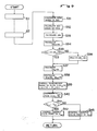
- a control sequence for controlling the speed reduction ratio and the throttle valve to establish and obtain the target acceleration will be described below with reference to FIG. 3.
- FIG. 3 shows a control process according to the present invention.
- an accelerator opening (the amount of depression of the accelerator pedal) ⁇ AP is read in a step S1, and then a vehicle speed V is read in a step S2.
- a target terminal acceleration Go to be reached is determined from the accelerator opening ⁇ AP and the vehicle speed V in a step S3.
- a target terminal acceleration Go which corresponds to the accelerator opening ⁇ AP and the vehicle speed V that are thus read is read from FIG.
- the target terminal acceleration for obtaining a desired driver's acceleration feeling corresponding to the accelerator pedal depression at the vehicle speed can be achieved.
- a calculative acceleration G CAL corresponding to the present reserved power of the engine is calculated in a step S4. Since the reserved horsepower Pa of the engine is given by the equation (5) above, the predicted acceleration Ga is calculated using the reserved horsepower Pa according to the equation (5), and the predicted acceleration Ga thus determined is the calculative acceleration G CAL .
- a corrective value dGon/dt for the calculative acceleration G CAL which is necessary to vary the present acceleration (calculative acceleration G CAL ) up to the target terminal acceleration Go along a desired characteristic curve, is calculated on the basis of the acceleration difference ⁇ G in a step S6.
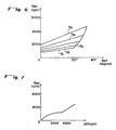
- the corrective value dGon/dt is determined, for example, using a map or graph as shown in FIG. 5 which contains calculated corrective values corresponding to different values of the acceleration difference ⁇ G. Therefore, the desired corrective value dGon/dt corresponding to the present acceleration difference ⁇ G calculated in the step S5 can be found in the graph of FIG. 5 according to the solid-line curve therein.
- This target present acceleration Gon is an acceleration which is required at the present time to vary the present calculative acceleration G CAL up to the target terminal acceleration Go along the desired characteristic curve.
- the throttle valve opening and the speed reduction ratio of the transmission are controlled in order to achieve the target present acceleration Gon.
- the engine rotational speed Ne is read in a step S11, and then a target engine rotational speed Neo which corresponds to the accelerator opening ⁇ AP and the vehicle speed V that have already been read in is calculated in a step S12.
- values of the target engine rotational speed Neo are preset for the vehicle speeds V1 through V5 and plotted against values of the accelerator opening ⁇ AP . Therefore, the target engine rotational speed Neo is determined in the step S12 which corresponds to the present accelerator opening ⁇ AP and vehicle speed Neo that have been read in the steps S1, S2.
- the target rate dNeo/dt is determined from the graph of FIG. 7, for example, which contains preset rates of change of the engine rotational speed such that the engine rotational speed will vary along a desired characteristic curve depending on the rotational speed difference ⁇ Ne.
- control goes to a step S15 in which the intake vacuum P B of the engine as detected by the vacuum sensor 161 is read, and a present engine horsepower P SRL is calculated according to the intake vacuum P B and the engine rotational speed Ne. Thereafter, a target engine horsepower Pson required to obtain the target present acceleration Gon is determined according to the following equation (10) in a step S16:
- a target intake vacuum P Bon which is required to vary the present engine horsepower P SRL up to the target engine horsepower Pson at the engine rotational speed Ne at this time, is calculated in a step S17.
- a map containing values of the engine horsepower Ps depending on values of the engine intake vacuum P B and values of the engine rotational speed Ne may be employed, and the engine horsepower corresponding to the target engine horsepower Pson and the engine rotational speed Ne may be determined from the map.
- the throttle valve of the engine may then be controlled in order to achieve the target intake vacuum P Bon which is thus obtained.
- P Bon target intake vacuum
- the throttle valve opening is reduced smaller than a predetermined opening and the intake vacuum becomes higher than a predetermined level P BG , the engine horsepower is very small, and the throttle valve opening control is not effective enough to adjust the engine horsepower.
- a step S18 determines whether the target intake vacuum P Bon is lower than the predetermined value P BG or not, so that different control modes will be performed in case P Bon ⁇ P BG or P Bon ⁇ P BG .
- the motor vehicle can be accelerated (or decelerated) according to the target present acceleration Gon.
- control goes from the step S18 to a step S22 in which the engine throttle valve is controlled so that the intake vacuum P B is equalized to the predetermined value P BG (constant). Since the engine horsepower cannot be adjusted by the throttle valve control at this time, the transmission control is effected to make up for the engine horsepower adjustment.
- a corrective component diG/dt is calculated according to the following equation (11) in a step S23.
- di G /dt C3 ⁇ Ne V2 ⁇ (Gon - G CAL ) (11)
- the solenoid-operated valves 151, 152 are controlled, i.e., the speed reduction ratio of the transmission is controlled, in order to obtain the rate di/dt in a step S24.
- the motor vehicle can also be accelerated (or decelerated) according to the target present acceleration Gon.
- the above flow or control sequence is cyclically repeated every preset period of time (e.g., every 10 ms) for continuously controlling the speed reduction ratio along a desired acceleration (or deceleration) characteristic curve. If the speed reduction ratio is controlled through the duty ratio control of the solenoid-operated valves as with the illustrated embodiment, then a control signal for the solenoid-operated valves is issued every 100 ms, for example, even though the control sequence is repeated every 10 ms, because the mechanical parts of the solenoid-operated valves have slow responses.
- a target present acceleration Gon is determined in steps 1 through 7 which are exactly the same as the steps 1 through 7 shown in FIG. 3. Therefore, the steps 1 through 7 shown in FIG. 8 will not be described below.
- Steps S11 through S22 shown in FIG. 8 are also identical to those shown in FIG. 3.
- the rate di/dt of change of the speed reduction ratio is determined according to the equation (9), and if the target intake vacuum P Bon is equal to or higher than the predetermined value P BG , the corrective component determined according to the equation (11) is added to the equation (9), thus obtaining the rate di/dt of change of the speed reduction ratio, and the speed reduction ratio is controlled on the basis of the rate di/dt thus determined.
- the control mode shown in FIG. 8 can control the speed reduction ratio with a good response.
- a target present acceleration Gon is determined in steps 1 through 7 which are exactly the same as the steps 1 through 7 shown in FIG. 3. Therefore, the steps 1 through 7 shown in FIG. 9 will not be described below.
- step S31 calculates a target engine horsepower Pson required to obtain the target present acceleration Gon.
- This calculation is the same as the calculation in the step S17 in the control sequence of FIG. 3.
- the present engine horsepower P SRL is calculated from the engine intake vacuum P B and the engine rotational speed Ne, and the target engine horsepower Pson required to obtain the target present acceleration Gon is determined according to the equation (10).
- a target engine rotational speed Neo is calculated on the basis of the target engine horsepower Pson in a step S32.
- the target engine rotational speed Neo may be found from a map which contains data representative of the relationship between value of the engine horsepower P and values of the engine rotational speed Ne on a minimum fuel consumption curve, for example. This allows the speed reduction ratio to be controlled for better fuel economy.
- the difference ⁇ Ne between the target engine rotational speed Neo and the present engine rotational speed Ne is calculated in a step S33.
- a present target rate dNeo/dt of change of the engine rotational speed which rate is required to vary the present engine rotational speed Ne up to the target rotational speed Neo along a desired characteristic curve, is calculated in a step S34.
- the target rate dNeo/dt is determined from the graph of FIG. 7, for example, which contains preset rates of change of the engine rotational speed such that the engine rotational speed will vary along a desired characteristic curve depending on the rotational speed difference ⁇ Ne.
- a step S35 determines whether the target rate dNeo/dt of change of the engine rotational speed is smaller than a predetermined value dN G /dt or not. If the rate dNeo/dt is larger than or equal to the predetermined value dN G /dt, then the predetermined value dN G /dt is set as the target rate dNeo/dt of change of the engine rotational speed. Then, a component di N /dt corresponding to the target rate dNeo/dt of change of the engine rotational speed is calculated in a step S37.
- a component dia/dt corresponding to the predicted acceleration and a corrective component di G /dt are calculated according to the equations (8) and (11) in a step S38.
- the calculative acceleration G CAL may be calculated as a value under a reference intake vacuum (which may have a substantially intermediate value of - 300 Hg, for example). This allows the speed reduction ratio to be controlled for better fuel economy though control responses are slightly lowered.
- the throttle valve of the engine is controlled in steps S40 through S43.
- This throttle valve control is the same as the steps S18 through S22 shown in FIG. 3.
- a target intake vacuum P Bon required to vary the engine horsepower up to a target horsepower Pson is determined from the target engine horsepower Pson and the engine rotational speed Ne, and the throttle valve is controlled so that the target intake vacuum P Bon will be obtained.
- the different control modes are performed depending on whether the target intake vacuum P Bon is higher or lower than the predetermined value P BG .
- control method has been described as being applied to a continuously variable transmission which comprises a hydraulic pump and a hydraulic motor. However, the same principles are also applicable to any of various other types of continuously variable transmission.
- a target terminal acceleration Go is established according to an indication of the driver's intention for acceleration or deceleration, such as the amount of depression of the accelerator pedal, and also to an indication of the speed of the motor vehicle, and a present calculative acceleration G CAL is calculated on the basis of a reserved power at the present time of the engine which drives the continuously variable transmission.
- the throttle valve of the engine and the continuously variable transmission are controlled so that the target present acceleration Gon will be reached.
- the motor vehicle runs in a manner to meet the driver's demand for acceleration, represented by the depression by the driver of the accelerator pedal. Since the transmission and the throttle valve are controlled using, as a target value, the acceleration (or deceleration) whose changes can be sensed by the driver, the desired characteristic which meets the demand of the driver is reliably achieved.
Applications Claiming Priority (2)
| Application Number | Priority Date | Filing Date | Title |
|---|---|---|---|
| JP70151/89 | 1989-03-22 | ||
| JP1070151A JPH0686193B2 (ja) | 1989-03-22 | 1989-03-22 | スロットル制御付き無段変速機変速制御方法 |
Publications (3)
| Publication Number | Publication Date |
|---|---|
| EP0389262A2 true EP0389262A2 (fr) | 1990-09-26 |
| EP0389262A3 EP0389262A3 (fr) | 1991-01-09 |
| EP0389262B1 EP0389262B1 (fr) | 1994-01-19 |
Family
ID=13423293
Family Applications (1)
| Application Number | Title | Priority Date | Filing Date |
|---|---|---|---|
| EP90303039A Expired - Lifetime EP0389262B1 (fr) | 1989-03-22 | 1990-03-21 | Procédé de contrôle d'une transmission à réglage continu et étrangleur |
Country Status (4)
| Country | Link |
|---|---|
| US (1) | US5218540A (fr) |
| EP (1) | EP0389262B1 (fr) |
| JP (1) | JPH0686193B2 (fr) |
| DE (1) | DE69006060T2 (fr) |
Cited By (9)
| Publication number | Priority date | Publication date | Assignee | Title |
|---|---|---|---|---|
| EP0424088A2 (fr) * | 1989-10-16 | 1991-04-24 | Honda Giken Kogyo Kabushiki Kaisha | Système de commande d'une transmission automatique |
| EP1040956A1 (fr) * | 1999-03-31 | 2000-10-04 | Fuji Jukogyo Kabushiki Kaisha | Contrôle combiné pour un moteur à explosion et une boíte de vitesse automatique |
| WO2001087662A1 (fr) * | 2000-05-16 | 2001-11-22 | Nissan Motor Co., Ltd. | Systeme de regulation de la vitesse d'un vehicule |
| EP1297990A2 (fr) * | 2001-09-26 | 2003-04-02 | Nissan Motor Company, Limited | Système de commande de la force motrice d'un véhicule |
| WO2003031847A1 (fr) * | 2001-10-12 | 2003-04-17 | Clark Equipment Company | Systeme de commande d'un engin sur roues |
| EP1275552A3 (fr) * | 2001-07-13 | 2005-05-25 | Deere & Company | Système et appareil de commande d'une transmission hydrostatique pour tracteur ou véhicule utilitaire |
| EP1873031A1 (fr) * | 2006-06-29 | 2008-01-02 | Brueninghaus Hydromatik Gmbh | Procédé et unité de commande pour un entraînement de roulement |
| WO2008000382A1 (fr) * | 2006-06-28 | 2008-01-03 | Brueninghaus Hydromatik Gmbh | Procédé pour commander un rapport de transmission |
| EP1901053A1 (fr) * | 2005-07-05 | 2008-03-19 | Toyota Jidosha Kabushiki Kaisha | Dispositif d évaluation de sensation d accélération et dispositif de commande de véhicule |
Families Citing this family (18)
| Publication number | Priority date | Publication date | Assignee | Title |
|---|---|---|---|---|
| JP3003237B2 (ja) * | 1991-02-04 | 2000-01-24 | トヨタ自動車株式会社 | 希薄燃焼内燃機関を備えた車両用無段変速機の制御装置 |
| JP2641004B2 (ja) * | 1992-01-21 | 1997-08-13 | 本田技研工業株式会社 | 車両用無段変速機における加速および減速スキップ変速制御方法 |
| US5544056A (en) * | 1995-01-23 | 1996-08-06 | Seireg; Ali A. | Computerized control of automobile speed |
| JP2004124959A (ja) * | 2002-09-30 | 2004-04-22 | Jatco Ltd | 自動変速機の制御装置 |
| JP4071649B2 (ja) * | 2003-02-27 | 2008-04-02 | ジヤトコ株式会社 | ベルト式無段変速機における変速制御装置 |
| CN100364799C (zh) * | 2004-06-04 | 2008-01-30 | 雅马哈发动机株式会社 | 燃料油箱盖组合及具备其的车辆 |
| US7862459B2 (en) * | 2007-03-20 | 2011-01-04 | Yamaha Hatsudoki Kabushiki Kaisha | Transmission, power unit having the same, vehicle, controller for transmission, and method of controlling transmission |
| JP4770812B2 (ja) * | 2007-08-22 | 2011-09-14 | 日産自動車株式会社 | 車両の運動制御装置 |
| US8216109B2 (en) | 2007-09-28 | 2012-07-10 | Caterpillar Inc. | Torque-based control system for a continuously variable transmission |
| AU2011261248B2 (en) | 2010-06-03 | 2015-09-17 | Polaris Industries Inc. | Electronic throttle control |
| EP3212484A2 (fr) | 2014-10-31 | 2017-09-06 | Polaris Industries Inc. | Système et procédé de commande d'un véhicule |
| US9759313B2 (en) | 2014-11-26 | 2017-09-12 | Polaris Industries Inc. | Electronic shifting of a transmission |
| US9746070B2 (en) | 2014-11-26 | 2017-08-29 | Polaris Industries Inc. | Electronic control of a transmission |
| US11110913B2 (en) | 2016-11-18 | 2021-09-07 | Polaris Industries Inc. | Vehicle having adjustable suspension |
| US10406884B2 (en) | 2017-06-09 | 2019-09-10 | Polaris Industries Inc. | Adjustable vehicle suspension system |
| US11834049B2 (en) * | 2017-12-15 | 2023-12-05 | Nissan Motor Co., Ltd. | Method and device for controlling hybrid vehicle |
| JP6832303B2 (ja) * | 2018-02-15 | 2021-02-24 | トヨタテクニカルディベロップメント株式会社 | 制御装置及びその制御方法と制御プログラム |
| CA3182725A1 (fr) | 2020-07-17 | 2022-01-20 | Polaris Industries Inc. | Suspensions reglables et fonctionnement de vehicule pour vehicules de loisir hors-route |
Citations (4)
| Publication number | Priority date | Publication date | Assignee | Title |
|---|---|---|---|---|
| US4337511A (en) * | 1978-07-15 | 1982-06-29 | Robert Bosch Gmbh | Digital control apparatus for the running speed of a motor vehicle |
| US4479184A (en) * | 1980-11-05 | 1984-10-23 | Toyota Jidosha Kogyo Kabushiki Kaisha | Device for maintaining a constant vehicle speed |
| US4541052A (en) * | 1982-12-20 | 1985-09-10 | General Motors Corporation | Motor vehicle power output regulation control system |
| US4677560A (en) * | 1983-12-08 | 1987-06-30 | Robert Bosch Gmbh | Speed control for motor vehicles with microcomputer step-by-step control |
Family Cites Families (23)
| Publication number | Priority date | Publication date | Assignee | Title |
|---|---|---|---|---|
| SE428720C (sv) * | 1977-07-08 | 1984-08-21 | Kockums Ind Ab | Sett att styra en borbrenningsmotor med effektreglage for reglering av motorns varvtal och en hydrostatisk transmission med variabelt utvexlingsforhallande |
| JPS58180864A (ja) * | 1982-04-19 | 1983-10-22 | Nissan Motor Co Ltd | Vベルト式無段変速機の変速制御装置 |
| US4630508A (en) * | 1983-03-28 | 1986-12-23 | Wabco Westinghouse Fahrzeugbremsen Gmbh | Method and apparatus to determine constant speed torque on an engine |
| JPH066979B2 (ja) * | 1983-08-22 | 1994-01-26 | トヨタ自動車株式会社 | 車両用無段変速機の制御装置 |
| JPS6098253A (ja) * | 1983-10-31 | 1985-06-01 | Mazda Motor Corp | 無段変速機の制御方法 |
| JP2506630B2 (ja) * | 1984-09-13 | 1996-06-12 | アイシン精機株式会社 | Cvt制御方式 |
| JPS61119856A (ja) * | 1984-09-25 | 1986-06-07 | Toyota Motor Corp | 無段変速機を備えた車両の駆動力制御装置 |
| KR930001391B1 (ko) * | 1985-06-12 | 1993-02-27 | 미쯔비시지도샤고교 가부시끼가이샤 | 차량용 엔진 제어장치 |
| JPH0749824B2 (ja) * | 1986-03-06 | 1995-05-31 | 本田技研工業株式会社 | 車両用無段変速機の変速制御方法 |
| JPH086797B2 (ja) * | 1986-07-15 | 1996-01-29 | 本田技研工業株式会社 | 車両用無段変速機の変速制御方法 |
| JPH0721306B2 (ja) * | 1986-08-19 | 1995-03-08 | 本田技研工業株式会社 | 車両用無段変速機の変速制御装置 |
| JPH0721307B2 (ja) * | 1986-08-19 | 1995-03-08 | 本田技研工業株式会社 | 車両用無段変速機の変速制御装置 |
| JPH0721308B2 (ja) * | 1986-08-19 | 1995-03-08 | 本田技研工業株式会社 | 車両用無段変速機の変速制御装置 |
| JPH0721305B2 (ja) * | 1986-08-19 | 1995-03-08 | 本田技研工業株式会社 | 車両用無段変速機の変速制御装置 |
| JPS6353130A (ja) * | 1986-08-23 | 1988-03-07 | Fuji Heavy Ind Ltd | 無段変速機の制御装置 |
| US4893526A (en) * | 1986-09-19 | 1990-01-16 | Toyota Jidosha Kabushiki Kaisha | Continuous variable transmission control system |
| DE3636463A1 (de) * | 1986-10-25 | 1988-05-05 | Daimler Benz Ag | Verfahren und vorrichtung zur steuerung des stufenlos veraenderlichen uebersetzungsverhaeltnisses eines kegelscheibenumschlingungsgetriebes in einem kraftfahrzeug |
| JP2784919B2 (ja) * | 1987-08-10 | 1998-08-13 | スズキ株式会社 | 連続可変変速機制御方法 |
| JP2821531B2 (ja) * | 1987-08-31 | 1998-11-05 | 富士重工業株式会社 | 無段変速機付車両の定速走行制御装置 |
| JPH0198756A (ja) * | 1987-10-12 | 1989-04-17 | Honda Motor Co Ltd | 無段変速機の変速制御装置 |
| JPH07117157B2 (ja) * | 1987-11-16 | 1995-12-18 | 本田技研工業株式会社 | 車両用無段変速機の変速制御方法 |
| JP2882528B2 (ja) * | 1988-07-20 | 1999-04-12 | 本田技研工業株式会社 | 無段変速機のスロットル制御付き変速制御方法 |
| JP3746303B2 (ja) * | 1993-02-26 | 2006-02-15 | ソニー株式会社 | 電界効果トランジスタ |
-
1989
- 1989-03-22 JP JP1070151A patent/JPH0686193B2/ja not_active Expired - Fee Related
-
1990
- 1990-03-21 EP EP90303039A patent/EP0389262B1/fr not_active Expired - Lifetime
- 1990-03-21 DE DE90303039T patent/DE69006060T2/de not_active Expired - Fee Related
- 1990-03-22 US US07/497,510 patent/US5218540A/en not_active Expired - Lifetime
Patent Citations (4)
| Publication number | Priority date | Publication date | Assignee | Title |
|---|---|---|---|---|
| US4337511A (en) * | 1978-07-15 | 1982-06-29 | Robert Bosch Gmbh | Digital control apparatus for the running speed of a motor vehicle |
| US4479184A (en) * | 1980-11-05 | 1984-10-23 | Toyota Jidosha Kogyo Kabushiki Kaisha | Device for maintaining a constant vehicle speed |
| US4541052A (en) * | 1982-12-20 | 1985-09-10 | General Motors Corporation | Motor vehicle power output regulation control system |
| US4677560A (en) * | 1983-12-08 | 1987-06-30 | Robert Bosch Gmbh | Speed control for motor vehicles with microcomputer step-by-step control |
Cited By (17)
| Publication number | Priority date | Publication date | Assignee | Title |
|---|---|---|---|---|
| EP0424088A3 (en) * | 1989-10-16 | 1991-10-09 | Honda Giken Kogyo Kabushiki Kaisha | Method of controlling automatic transmission |
| US5754428A (en) * | 1989-10-16 | 1998-05-19 | Honda Giken Kogyo Kabushiki Kaisha | Method of controlling speed reduction ratio in a continuously variable transmission |
| EP0424088A2 (fr) * | 1989-10-16 | 1991-04-24 | Honda Giken Kogyo Kabushiki Kaisha | Système de commande d'une transmission automatique |
| EP1040956A1 (fr) * | 1999-03-31 | 2000-10-04 | Fuji Jukogyo Kabushiki Kaisha | Contrôle combiné pour un moteur à explosion et une boíte de vitesse automatique |
| WO2001087662A1 (fr) * | 2000-05-16 | 2001-11-22 | Nissan Motor Co., Ltd. | Systeme de regulation de la vitesse d'un vehicule |
| US6732039B2 (en) | 2000-05-16 | 2004-05-04 | Nissan Motor Co., Ltd. | Vehicle speed control system |
| EP1275552A3 (fr) * | 2001-07-13 | 2005-05-25 | Deere & Company | Système et appareil de commande d'une transmission hydrostatique pour tracteur ou véhicule utilitaire |
| EP1297990A2 (fr) * | 2001-09-26 | 2003-04-02 | Nissan Motor Company, Limited | Système de commande de la force motrice d'un véhicule |
| EP1297990A3 (fr) * | 2001-09-26 | 2006-01-04 | Nissan Motor Company, Limited | Système de commande de la force motrice d'un véhicule |
| US6896088B2 (en) | 2001-10-12 | 2005-05-24 | Clark Equipment Company | Operation of wheeled work machine |
| WO2003031847A1 (fr) * | 2001-10-12 | 2003-04-17 | Clark Equipment Company | Systeme de commande d'un engin sur roues |
| EP1901053A1 (fr) * | 2005-07-05 | 2008-03-19 | Toyota Jidosha Kabushiki Kaisha | Dispositif d évaluation de sensation d accélération et dispositif de commande de véhicule |
| EP1901053A4 (fr) * | 2005-07-05 | 2008-12-10 | Toyota Motor Co Ltd | Dispositif d évaluation de sensation d accélération et dispositif de commande de véhicule |
| CN101208590B (zh) * | 2005-07-05 | 2010-06-16 | 丰田自动车株式会社 | 加速感运算装置以及车辆控制装置 |
| US8073576B2 (en) | 2005-07-05 | 2011-12-06 | Toyota Jidosha Kabushiki Kaisha | Acceleration sensation evaluating device and vehicle controller |
| WO2008000382A1 (fr) * | 2006-06-28 | 2008-01-03 | Brueninghaus Hydromatik Gmbh | Procédé pour commander un rapport de transmission |
| EP1873031A1 (fr) * | 2006-06-29 | 2008-01-02 | Brueninghaus Hydromatik Gmbh | Procédé et unité de commande pour un entraînement de roulement |
Also Published As
| Publication number | Publication date |
|---|---|
| EP0389262B1 (fr) | 1994-01-19 |
| DE69006060T2 (de) | 1994-05-05 |
| US5218540A (en) | 1993-06-08 |
| JPH02249727A (ja) | 1990-10-05 |
| EP0389262A3 (fr) | 1991-01-09 |
| DE69006060D1 (de) | 1994-03-03 |
| JPH0686193B2 (ja) | 1994-11-02 |
Similar Documents
| Publication | Publication Date | Title |
|---|---|---|
| EP0389262B1 (fr) | Procédé de contrôle d'une transmission à réglage continu et étrangleur | |
| US5754428A (en) | Method of controlling speed reduction ratio in a continuously variable transmission | |
| EP0352110B1 (fr) | Méthode de commande d'une transmission continue en combinaison avec la commande de gaz du moteur | |
| US4961315A (en) | Method of controlling speed reduction ratio of continuously variable speed transmission | |
| US4956972A (en) | Method of controlling speed reduction ratio for a continuously variable speed transmission | |
| US5419128A (en) | Method of controlling speed reduction ratios of continuously variable transmission for automotive vehicles | |
| US4976169A (en) | Method of controlling speed reduction ratio for a continuously variable transmissions | |
| EP0312275B1 (fr) | Variateur continu de vitesse | |
| EP0313286B1 (fr) | Méthode de commande du rapport de transmission d'un variateur continu de vitesse | |
| EP0317290B1 (fr) | Procédé de commande pour le rapport d'une transmission à variation de vitesse infinie | |
| US4962679A (en) | Method of controlling speed reduction ratio for a continuously variable speed transmission | |
| US4951468A (en) | Method of determining duty ratio used for operational control of a solenoid | |
| US4913005A (en) | Method of controlling speed reduction ratio for a continuously variable speed transmission | |
| EP0552942B1 (fr) | Procédé de commande de transmissions à variation de vitesse continue | |
| US4939981A (en) | Hydraulic servo cylinder device for controlling continuously variable speed transmission | |
| JPH0726680B2 (ja) | 車両用無段変速機の変速制御装置 | |
| JP2516782B2 (ja) | 車両用無段変速機の変速制御方法 | |
| JP2649227B2 (ja) | 車両のクラッチ制御方法 | |
| JPH0822655B2 (ja) | 車両用無段変速機の変速制御方法 | |
| JPH07111219B2 (ja) | 車両用段変速機の変速制御のためのクラッチ接続完了判断方法 |
Legal Events
| Date | Code | Title | Description |
|---|---|---|---|
| PUAI | Public reference made under article 153(3) epc to a published international application that has entered the european phase |
Free format text: ORIGINAL CODE: 0009012 |
|
| AK | Designated contracting states |
Kind code of ref document: A2 Designated state(s): DE FR GB IT |
|
| PUAL | Search report despatched |
Free format text: ORIGINAL CODE: 0009013 |
|
| AK | Designated contracting states |
Kind code of ref document: A3 Designated state(s): DE FR GB IT |
|
| RHK1 | Main classification (correction) |
Ipc: G05D 13/58 |
|
| 17P | Request for examination filed |
Effective date: 19910222 |
|
| 17Q | First examination report despatched |
Effective date: 19930630 |
|
| GRAA | (expected) grant |
Free format text: ORIGINAL CODE: 0009210 |
|
| ITF | It: translation for a ep patent filed |
Owner name: BARZANO' E ZANARDO ROMA S.P.A. |
|
| AK | Designated contracting states |
Kind code of ref document: B1 Designated state(s): DE FR GB IT |
|
| REF | Corresponds to: |
Ref document number: 69006060 Country of ref document: DE Date of ref document: 19940303 |
|
| ET | Fr: translation filed | ||
| PLBE | No opposition filed within time limit |
Free format text: ORIGINAL CODE: 0009261 |
|
| STAA | Information on the status of an ep patent application or granted ep patent |
Free format text: STATUS: NO OPPOSITION FILED WITHIN TIME LIMIT |
|
| 26N | No opposition filed | ||
| ITTA | It: last paid annual fee | ||
| PGFP | Annual fee paid to national office [announced via postgrant information from national office to epo] |
Ref country code: GB Payment date: 19980316 Year of fee payment: 9 |
|
| PGFP | Annual fee paid to national office [announced via postgrant information from national office to epo] |
Ref country code: FR Payment date: 19980317 Year of fee payment: 9 |
|
| PG25 | Lapsed in a contracting state [announced via postgrant information from national office to epo] |
Ref country code: GB Free format text: LAPSE BECAUSE OF NON-PAYMENT OF DUE FEES Effective date: 19990321 |
|
| GBPC | Gb: european patent ceased through non-payment of renewal fee |
Effective date: 19990321 |
|
| PG25 | Lapsed in a contracting state [announced via postgrant information from national office to epo] |
Ref country code: FR Free format text: LAPSE BECAUSE OF NON-PAYMENT OF DUE FEES Effective date: 19991130 |
|
| REG | Reference to a national code |
Ref country code: FR Ref legal event code: ST |
|
| PGFP | Annual fee paid to national office [announced via postgrant information from national office to epo] |
Ref country code: DE Payment date: 20030403 Year of fee payment: 14 |
|
| PG25 | Lapsed in a contracting state [announced via postgrant information from national office to epo] |
Ref country code: DE Free format text: LAPSE BECAUSE OF NON-PAYMENT OF DUE FEES Effective date: 20041001 |
|
| PG25 | Lapsed in a contracting state [announced via postgrant information from national office to epo] |
Ref country code: IT Free format text: LAPSE BECAUSE OF NON-PAYMENT OF DUE FEES;WARNING: LAPSES OF ITALIAN PATENTS WITH EFFECTIVE DATE BEFORE 2007 MAY HAVE OCCURRED AT ANY TIME BEFORE 2007. THE CORRECT EFFECTIVE DATE MAY BE DIFFERENT FROM THE ONE RECORDED. Effective date: 20050321 |