EP0383308A2 - Bildlesevorrichtung - Google Patents
Bildlesevorrichtung Download PDFInfo
- Publication number
- EP0383308A2 EP0383308A2 EP90102904A EP90102904A EP0383308A2 EP 0383308 A2 EP0383308 A2 EP 0383308A2 EP 90102904 A EP90102904 A EP 90102904A EP 90102904 A EP90102904 A EP 90102904A EP 0383308 A2 EP0383308 A2 EP 0383308A2
- Authority
- EP
- European Patent Office
- Prior art keywords
- sensor
- optical system
- image reading
- reading device
- imaging optical
- Prior art date
- Legal status (The legal status is an assumption and is not a legal conclusion. Google has not performed a legal analysis and makes no representation as to the accuracy of the status listed.)
- Granted
Links
- 230000003287 optical effect Effects 0.000 claims abstract description 38
- 238000003384 imaging method Methods 0.000 claims abstract description 28
- 238000003491 array Methods 0.000 claims abstract description 16
- 239000000758 substrate Substances 0.000 claims abstract description 5
- 230000004075 alteration Effects 0.000 description 6
- 239000003086 colorant Substances 0.000 description 5
- 210000001747 pupil Anatomy 0.000 description 5
- 238000004519 manufacturing process Methods 0.000 description 4
- 230000015572 biosynthetic process Effects 0.000 description 2
- 238000005755 formation reaction Methods 0.000 description 2
- 238000000926 separation method Methods 0.000 description 2
- 230000005540 biological transmission Effects 0.000 description 1
- 230000003247 decreasing effect Effects 0.000 description 1
- 230000002093 peripheral effect Effects 0.000 description 1
Images


Classifications
-
- H—ELECTRICITY
- H04—ELECTRIC COMMUNICATION TECHNIQUE
- H04N—PICTORIAL COMMUNICATION, e.g. TELEVISION
- H04N1/00—Scanning, transmission or reproduction of documents or the like, e.g. facsimile transmission; Details thereof
- H04N1/46—Colour picture communication systems
- H04N1/48—Picture signal generators
- H04N1/486—Picture signal generators with separate detectors, each detector being used for one specific colour component
- H04N1/488—Picture signal generators with separate detectors, each detector being used for one specific colour component using beam-splitters
Definitions
- the present invention relates to a device for reading a color image utilizing a solid-state image sensor device or the like, and in particular to a color image reading device in which the light from an object is guided to a sensor such as a solid-state image sensor through an imaging optical system and color separation means.
- a device as shown in Fig. 1 is already known for line scanning an object such as an original document and reading the color image thereof with a solid-state image sensor array, such as a CCD sensor.
- the information on a part of an original surface 1 is illuminated by the light from an illuminating light source (not shown), and is read by the reflected light which is guided through an imaging optical system, then is separated into three colors through a three-piece (3P) prism 20 and are focused on three line CCD sensors 21, 22, 23.
- FIG. 3 shows a known structure of a color image reading device, utilizing such monolithic 3-line sensor as the image sensor, wherein, in scanning the information on an original surface 1 in the sub scanning direction, the light from said surface 1 is guided through an imaging optical system 29, then separated into three light beams of three colors by color-separating beam splitters 30, 31 with a dichroic selective transmission film, and said three light beams are focused on respectively corresponding line sensors of the monolithic 3-line sensor 32.
- a plate thickness t of the beam splitters 30, 31 provides a line distance 2 ⁇ 2t on the sensor 32. If said distance is selected in the order of 0.1 to 0.2 mm as explained above, the plate thickness t is about 35 to 70 ⁇ m, which is difficult to achieve in manufacture, in consideration of the surface flatness required.
- the object of the present invention is to provide an image reading device not associated with the above-mentioned drawbacks.
- the light beam bearing the image information from the object field is guided to plural light sensors through a telecentric imaging optical system and a blazed diffraction grating.
- This structure is capable of splitting the light from an image with a finite width into plural light beams of different wavelength regions without aberrations in color, and focusing said light beams on respectively corresponding lines of said plural line sensors.
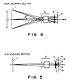
- Figs. 4 and 5 are cross-sectional views of a first embodiment of the image reading device of the present invention, respectively along a main scanning plane and along a sub scanning plane perpendicular to said main scanning plane.
- Image information on an original surface 1 constituting the object is line scanned in a sub scanning direction Z by means of a mirror (not shown) or the like positioned between said original surface 1 and a telecentric imaging optical system 2, and the light bearing the image information is guide, through said telecentric imaging optical system 2, to a three color-separating one-dimensional blazed diffraction grating 3.
- the image information on the original surface 1 is read by the relative movement in the sub scanning direction between the original surface 1 and an image reading unit (imaging optical system 2, diffraction grating 3 and sensor 4).
- the information-bearing light beam is split in the Z-direction into light beams 5, 6, 7 of three primary colors for image reading, for example red (R), green (G) and blue (B), which are respectively focused on sensor arrays 8, 9, 10 on a monolithic 3-line sensor 4.
- the sensor-bearing face of the sensor 4 is parallel to the sub scanning direction.
- Each of the sensor arrays 8, 9, 10 of the sensor 4 extends parallel to the main scanning direction, represented as Y in the drawing.
- Said sensor 4 is a monolithic 3-line sensor provided on a same substrate with three one-dimensional sensor arrays which are mutually spaced by a predetermined distance in a direction perpendicular to the direction of said arrays.
- the one-dimensional blazed diffraction grating 3 is provided between the imaging optical system 2 and the sensor 4, for separating the light from the object into plural light beams of different colors and guiding said light beams to respectively corresponding sensor arrays.
- the original surface 1 is illuminated by an unrepresented light source.
- Said one-dimensional glazed diffraction grating has a constant grating pitch in the sub scanning direction and a constant grating thickness in the main scanning direction.
- the one-dimensional glazed diffraction grating is disclosed in Applied Optics, 17 , 15, p. 2273 - 2279 (Aug. 1, 1978), and has a structure as shown in Fig. 6 which is a partial magnified view of Fig. 5, and in Fig. 7 showing the structure of a one-dimensional transmissive blazed diffraction grating.
- Fig. 8 is a schematic view showing image formation in a conventional non-telecentric imaging system.
- the aberration between the axial ray and off-axis ray in the Z-direction becomes as large as about 12 ⁇ m, which is apparently in excess of the aforementioned element size of 7 x 7 to 10 x 10 ⁇ m of the sensor 4. Said aberration can be reduced theoretically by decreasing the image angle ⁇ , but it cannot be reduced easily in order to compactize the entire device.
- phase difference resulting from the thicknesses d1, d2 of the diffraction grating 3 is governed by the following relationship: wherein ⁇ i is the phase difference (rad), and n ⁇ is the refractive index of the medium constituting the grating for the light of wavelength ⁇ .
- ⁇ i is the phase difference (rad)
- n ⁇ is the refractive index of the medium constituting the grating for the light of wavelength ⁇ .
- the telecentric imaging optical system 2 is employed for avoiding the above-mentioned drawback resulting from the image angle.
- the telecentric imaging optical system has the entrance pupil on the front focal plane as shown in Fig. 4, so that the exit pupil is present at an infinite distance.
- all the principal rays, including that corresponding to the image angle ⁇ emerge parallel to the optical axis. Consequently the emerging angle ⁇ ′ from the exit pupil is always zero regardless of the image angle ⁇ .
- the distance from the blazed diffraction grating 3 to the face of the 3-line sensor 4 is always l0 regardless of the image angle ⁇ , and ⁇ i remains always constant because the emerging angle ⁇ ′ is zero. It is therefore possible to prevent the aberration in the image position in the Z-direction and in the diffracted wavelength.
- the imaging optical system 2 is assumed to be completely telecentric, but a substantially telecentric system can be employed in practice without difficulty.
- an imaging optical system showing telecentric property within an emerging angle range of ⁇ 10° can be employed without practical drawback.
- the tolecentric imaging optical system employed in the foregoing embodiments is a reduction optical system, but the same advantage can be attained with a same-size optical system.
- a Selfoc lens array (trade name) 11 shown in Fig. 10 constitutes a telecentric optical system capable of providing a same-size erect image, and can provide the same advantage as in the first embodiment, when employed as the imaging optical system.
- Figs. 10A and 10B show a third embodiment of the image reading device of the present invention, seen respectively in a main scanning plane and a sub scanning plane.
- the present invention provides an image reading device adapted for realizing a compact and inexpensive color image reading apparatus, which forms, respectively on linear sensor arrays of a sensor, images separated satisfactorily in position and in color without aberrations in the image positions or in the diffracted wavelength even for a wide image reading width.
- An image reading device comprises a plural-line sensor containing plural one-dimensional sensor arrays formed on a substrate, a telecentric imaging optical system for forming the image of an object on the sensor, and a blazed diffraction grating positioned in the optical path between the imaging optical system and the sensor and adapted to separate the light from the object into plural color components and to guide thus color-separated lights to respectively corresponding the sensor arrays.
Landscapes
- Engineering & Computer Science (AREA)
- Multimedia (AREA)
- Signal Processing (AREA)
- Facsimile Scanning Arrangements (AREA)
- Facsimile Heads (AREA)
Applications Claiming Priority (2)
| Application Number | Priority Date | Filing Date | Title |
|---|---|---|---|
| JP1035692A JPH07121047B2 (ja) | 1989-02-15 | 1989-02-15 | カラー画像読取り装置 |
| JP35692/89 | 1989-02-15 |
Publications (3)
| Publication Number | Publication Date |
|---|---|
| EP0383308A2 true EP0383308A2 (de) | 1990-08-22 |
| EP0383308A3 EP0383308A3 (de) | 1991-03-20 |
| EP0383308B1 EP0383308B1 (de) | 1995-09-20 |
Family
ID=12448953
Family Applications (1)
| Application Number | Title | Priority Date | Filing Date |
|---|---|---|---|
| EP19900102904 Expired - Lifetime EP0383308B1 (de) | 1989-02-15 | 1990-02-14 | Bildlesevorrichtung |
Country Status (3)
| Country | Link |
|---|---|
| EP (1) | EP0383308B1 (de) |
| JP (1) | JPH07121047B2 (de) |
| DE (1) | DE69022443T2 (de) |
Cited By (7)
| Publication number | Priority date | Publication date | Assignee | Title |
|---|---|---|---|---|
| EP0440169A2 (de) * | 1990-01-30 | 1991-08-07 | Canon Kabushiki Kaisha | Bildlesevorrichtung |
| EP0533066A2 (de) * | 1991-09-18 | 1993-03-24 | Canon Kabushiki Kaisha | Bildlesegerät für Farbtrennung mit einem Beugungsgitter vom Reflektionstyp |
| EP0542513A1 (de) * | 1991-11-12 | 1993-05-19 | Canon Kabushiki Kaisha | Farbbildlesegerät |
| EP0543362A1 (de) * | 1991-11-20 | 1993-05-26 | Canon Kabushiki Kaisha | Farbbildlesegerät |
| EP0562760A1 (de) * | 1992-03-25 | 1993-09-29 | Scitex Corporation Ltd. | Verfahren um die spektrale Antwort einer Farbbildaufnahmeeinrichtung zu messen |
| DE102009056178A1 (de) | 2009-11-27 | 2011-06-01 | Carl Zeiss Ag | Bildaufnehmer, Bilderzeugungseinrichtung sowie Spektroskop für die ortsaufgelöste Spektroskopie |
| EP3606021A4 (de) * | 2017-03-24 | 2020-12-23 | Nippon Sheet Glass Company, Limited | Bildsensoreinheit und bildlesevorrichtung |
Families Citing this family (2)
| Publication number | Priority date | Publication date | Assignee | Title |
|---|---|---|---|---|
| JP2576311B2 (ja) * | 1991-07-26 | 1997-01-29 | キヤノン株式会社 | カラー画像読取装置 |
| JP2570946B2 (ja) * | 1992-06-25 | 1997-01-16 | キヤノン株式会社 | カラー画像読取装置 |
Citations (4)
| Publication number | Priority date | Publication date | Assignee | Title |
|---|---|---|---|---|
| US4540996A (en) * | 1982-05-11 | 1985-09-10 | Canon Kabushiki Kaisha | Recording apparatus |
| EP0167747A1 (de) * | 1984-05-09 | 1986-01-15 | Fuji Photo Film Co., Ltd. | Vorrichtung zum Auslesen von Strahlungsbildern |
| EP0240000A2 (de) * | 1986-04-02 | 1987-10-07 | Hewlett-Packard Company | Vorrichtung für elektromagnetische Wellenaufteilung |
| EP0302230A1 (de) * | 1987-07-15 | 1989-02-08 | Dainippon Screen Mfg. Co., Ltd. | Verfahren und Vorrichtung zur Bildinformationsaufname mit korrigierter Lesesteuerung |
Family Cites Families (3)
| Publication number | Priority date | Publication date | Assignee | Title |
|---|---|---|---|---|
| DE2645075C2 (de) * | 1976-10-06 | 1985-06-20 | Philips Patentverwaltung Gmbh, 2000 Hamburg | Optische Anordnung zur Erzeugung von spektral zerlegten Abbildungen |
| JPS5992667A (ja) * | 1982-11-19 | 1984-05-28 | Ricoh Co Ltd | 多色読取装置 |
| JPS6189764A (ja) * | 1984-10-08 | 1986-05-07 | Fuji Xerox Co Ltd | 画像読取走査装置 |
-
1989
- 1989-02-15 JP JP1035692A patent/JPH07121047B2/ja not_active Expired - Fee Related
-
1990
- 1990-02-14 DE DE1990622443 patent/DE69022443T2/de not_active Expired - Fee Related
- 1990-02-14 EP EP19900102904 patent/EP0383308B1/de not_active Expired - Lifetime
Patent Citations (4)
| Publication number | Priority date | Publication date | Assignee | Title |
|---|---|---|---|---|
| US4540996A (en) * | 1982-05-11 | 1985-09-10 | Canon Kabushiki Kaisha | Recording apparatus |
| EP0167747A1 (de) * | 1984-05-09 | 1986-01-15 | Fuji Photo Film Co., Ltd. | Vorrichtung zum Auslesen von Strahlungsbildern |
| EP0240000A2 (de) * | 1986-04-02 | 1987-10-07 | Hewlett-Packard Company | Vorrichtung für elektromagnetische Wellenaufteilung |
| EP0302230A1 (de) * | 1987-07-15 | 1989-02-08 | Dainippon Screen Mfg. Co., Ltd. | Verfahren und Vorrichtung zur Bildinformationsaufname mit korrigierter Lesesteuerung |
Non-Patent Citations (1)
| Title |
|---|
| APPLIED OPTICS, vol. 17, no. 15, 1st August 1978, pages 2273-2279; H. DAMMANN: "Color separation gratings" * |
Cited By (15)
| Publication number | Priority date | Publication date | Assignee | Title |
|---|---|---|---|---|
| EP0440169A2 (de) * | 1990-01-30 | 1991-08-07 | Canon Kabushiki Kaisha | Bildlesevorrichtung |
| EP0440169A3 (en) * | 1990-01-30 | 1993-01-13 | Canon Kabushiki Kaisha | Image reader |
| US5223703A (en) * | 1990-01-30 | 1993-06-29 | Canon Kabushiki Kaisha | Image reader with color decomposing blazed diffraction grating |
| EP0533066A3 (en) * | 1991-09-18 | 1993-05-05 | Canon Kabushiki Kaisha | Image reading apparatus with reflection type blazed diffraction grating for color separation |
| EP0533066A2 (de) * | 1991-09-18 | 1993-03-24 | Canon Kabushiki Kaisha | Bildlesegerät für Farbtrennung mit einem Beugungsgitter vom Reflektionstyp |
| US6028705A (en) * | 1991-09-18 | 2000-02-22 | Canon Kabushiki Kaisha | Image reading apparatus with reflection type blazed diffraction grating for color separation |
| EP0542513A1 (de) * | 1991-11-12 | 1993-05-19 | Canon Kabushiki Kaisha | Farbbildlesegerät |
| US5361145A (en) * | 1991-11-12 | 1994-11-01 | Canon Kabushiki Kaisha | Color image reading apparatus having correction means to correct for relative variations among image signals |
| EP0543362A1 (de) * | 1991-11-20 | 1993-05-26 | Canon Kabushiki Kaisha | Farbbildlesegerät |
| US5481381A (en) * | 1991-11-20 | 1996-01-02 | Canon Kabushiki Kaisha | Color image reading apparatus |
| EP0562760A1 (de) * | 1992-03-25 | 1993-09-29 | Scitex Corporation Ltd. | Verfahren um die spektrale Antwort einer Farbbildaufnahmeeinrichtung zu messen |
| DE102009056178A1 (de) | 2009-11-27 | 2011-06-01 | Carl Zeiss Ag | Bildaufnehmer, Bilderzeugungseinrichtung sowie Spektroskop für die ortsaufgelöste Spektroskopie |
| WO2011063939A1 (de) | 2009-11-27 | 2011-06-03 | Carl Zeiss Ag | Bildaufnehmer, bilderzeugungseinrichtung sowie spektroskop für die ortsaufgelöste spektroskopie |
| EP3606021A4 (de) * | 2017-03-24 | 2020-12-23 | Nippon Sheet Glass Company, Limited | Bildsensoreinheit und bildlesevorrichtung |
| US10917536B2 (en) | 2017-03-24 | 2021-02-09 | Nippon Sheet Glass Company, Limited | Image sensor unit and image reading device |
Also Published As
| Publication number | Publication date |
|---|---|
| JPH02214370A (ja) | 1990-08-27 |
| JPH07121047B2 (ja) | 1995-12-20 |
| DE69022443T2 (de) | 1996-04-11 |
| EP0383308A3 (de) | 1991-03-20 |
| EP0383308B1 (de) | 1995-09-20 |
| DE69022443D1 (de) | 1995-10-26 |
Similar Documents
| Publication | Publication Date | Title |
|---|---|---|
| EP0383307B1 (de) | Bildabtastvorrichtung | |
| US5187358A (en) | Image reading device having a telecentric optical system and a blazed diffraction grating | |
| US6016222A (en) | Color image reading apparatus | |
| EP0440169B1 (de) | Bildlesevorrichtung | |
| EP0383308B1 (de) | Bildlesevorrichtung | |
| EP0517235B1 (de) | Bildlesevorrichtung | |
| JP3432106B2 (ja) | カラー画像読取装置 | |
| EP0457281B1 (de) | Bildlesegerät | |
| US6028705A (en) | Image reading apparatus with reflection type blazed diffraction grating for color separation | |
| US6738164B1 (en) | Color image reading apparatus | |
| EP0731598B1 (de) | Farbbildlesegerät | |
| US5471321A (en) | Color image reading device | |
| JPH0546139B2 (de) | ||
| JPH0846748A (ja) | カラー画像読取装置 | |
| JP3033167B2 (ja) | カラー画像読取装置 | |
| JP3382288B2 (ja) | カラー画像読取装置 | |
| JPH0618807A (ja) | カラー画像読取装置 | |
| JPH04181864A (ja) | カラー画像読取装置 | |
| JPH03179868A (ja) | カラー画像読取装置 | |
| JPH02223270A (ja) | カラー画像読取り装置 | |
| JPH0818728A (ja) | カラー画像読取装置 | |
| JPH0534630A (ja) | カラー画像読取装置 | |
| JPH0787514B2 (ja) | カラー画像読取装置 | |
| JPH03234159A (ja) | カラー画像読取り装置 | |
| JPH10107952A (ja) | カラー画像読取装置 |
Legal Events
| Date | Code | Title | Description |
|---|---|---|---|
| PUAI | Public reference made under article 153(3) epc to a published international application that has entered the european phase |
Free format text: ORIGINAL CODE: 0009012 |
|
| AK | Designated contracting states |
Kind code of ref document: A2 Designated state(s): DE FR GB IT |
|
| PUAL | Search report despatched |
Free format text: ORIGINAL CODE: 0009013 |
|
| 17P | Request for examination filed |
Effective date: 19901221 |
|
| AK | Designated contracting states |
Kind code of ref document: A3 Designated state(s): DE FR GB IT |
|
| 17Q | First examination report despatched |
Effective date: 19930329 |
|
| GRAA | (expected) grant |
Free format text: ORIGINAL CODE: 0009210 |
|
| AK | Designated contracting states |
Kind code of ref document: B1 Designated state(s): DE FR GB IT |
|
| REF | Corresponds to: |
Ref document number: 69022443 Country of ref document: DE Date of ref document: 19951026 |
|
| ET | Fr: translation filed | ||
| ITF | It: translation for a ep patent filed | ||
| PLBE | No opposition filed within time limit |
Free format text: ORIGINAL CODE: 0009261 |
|
| STAA | Information on the status of an ep patent application or granted ep patent |
Free format text: STATUS: NO OPPOSITION FILED WITHIN TIME LIMIT |
|
| 26N | No opposition filed | ||
| REG | Reference to a national code |
Ref country code: GB Ref legal event code: IF02 |
|
| PGFP | Annual fee paid to national office [announced via postgrant information from national office to epo] |
Ref country code: GB Payment date: 20060208 Year of fee payment: 17 |
|
| PGFP | Annual fee paid to national office [announced via postgrant information from national office to epo] |
Ref country code: DE Payment date: 20060209 Year of fee payment: 17 |
|
| PGFP | Annual fee paid to national office [announced via postgrant information from national office to epo] |
Ref country code: FR Payment date: 20060220 Year of fee payment: 17 |
|
| PGFP | Annual fee paid to national office [announced via postgrant information from national office to epo] |
Ref country code: IT Payment date: 20060228 Year of fee payment: 17 |
|
| GBPC | Gb: european patent ceased through non-payment of renewal fee |
Effective date: 20070214 |
|
| REG | Reference to a national code |
Ref country code: FR Ref legal event code: ST Effective date: 20071030 |
|
| PG25 | Lapsed in a contracting state [announced via postgrant information from national office to epo] |
Ref country code: DE Free format text: LAPSE BECAUSE OF NON-PAYMENT OF DUE FEES Effective date: 20070901 |
|
| PG25 | Lapsed in a contracting state [announced via postgrant information from national office to epo] |
Ref country code: GB Free format text: LAPSE BECAUSE OF NON-PAYMENT OF DUE FEES Effective date: 20070214 Ref country code: FR Free format text: LAPSE BECAUSE OF NON-PAYMENT OF DUE FEES Effective date: 20070228 |
|
| PG25 | Lapsed in a contracting state [announced via postgrant information from national office to epo] |
Ref country code: IT Free format text: LAPSE BECAUSE OF NON-PAYMENT OF DUE FEES Effective date: 20070214 |
|
| P01 | Opt-out of the competence of the unified patent court (upc) registered |
Effective date: 20240326 |
|
| P03 | Opt-out of the competence of the unified patent court (upc) deleted |