EP0371880A2 - Méthode et appareil pour la commande et détection d'un laser utilisé pour enregistrement - Google Patents
Méthode et appareil pour la commande et détection d'un laser utilisé pour enregistrement Download PDFInfo
- Publication number
- EP0371880A2 EP0371880A2 EP89403314A EP89403314A EP0371880A2 EP 0371880 A2 EP0371880 A2 EP 0371880A2 EP 89403314 A EP89403314 A EP 89403314A EP 89403314 A EP89403314 A EP 89403314A EP 0371880 A2 EP0371880 A2 EP 0371880A2
- Authority
- EP
- European Patent Office
- Prior art keywords
- laser beam
- recording
- recording medium
- output
- data
- Prior art date
- Legal status (The legal status is an assumption and is not a legal conclusion. Google has not performed a legal analysis and makes no representation as to the accuracy of the status listed.)
- Granted
Links
Images


Classifications
-
- G—PHYSICS
- G11—INFORMATION STORAGE
- G11B—INFORMATION STORAGE BASED ON RELATIVE MOVEMENT BETWEEN RECORD CARRIER AND TRANSDUCER
- G11B19/00—Driving, starting, stopping record carriers not specifically of filamentary or web form, or of supports therefor; Control thereof; Control of operating function ; Driving both disc and head
- G11B19/02—Control of operating function, e.g. switching from recording to reproducing
-
- G—PHYSICS
- G11—INFORMATION STORAGE
- G11B—INFORMATION STORAGE BASED ON RELATIVE MOVEMENT BETWEEN RECORD CARRIER AND TRANSDUCER
- G11B7/00—Recording or reproducing by optical means, e.g. recording using a thermal beam of optical radiation by modifying optical properties or the physical structure, reproducing using an optical beam at lower power by sensing optical properties; Record carriers therefor
- G11B7/12—Heads, e.g. forming of the optical beam spot or modulation of the optical beam
- G11B7/125—Optical beam sources therefor, e.g. laser control circuitry specially adapted for optical storage devices; Modulators, e.g. means for controlling the size or intensity of optical spots or optical traces
- G11B7/126—Circuits, methods or arrangements for laser control or stabilisation
-
- G—PHYSICS
- G11—INFORMATION STORAGE
- G11B—INFORMATION STORAGE BASED ON RELATIVE MOVEMENT BETWEEN RECORD CARRIER AND TRANSDUCER
- G11B7/00—Recording or reproducing by optical means, e.g. recording using a thermal beam of optical radiation by modifying optical properties or the physical structure, reproducing using an optical beam at lower power by sensing optical properties; Record carriers therefor
- G11B7/004—Recording, reproducing or erasing methods; Read, write or erase circuits therefor
- G11B7/0045—Recording
-
- G—PHYSICS
- G11—INFORMATION STORAGE
- G11B—INFORMATION STORAGE BASED ON RELATIVE MOVEMENT BETWEEN RECORD CARRIER AND TRANSDUCER
- G11B7/00—Recording or reproducing by optical means, e.g. recording using a thermal beam of optical radiation by modifying optical properties or the physical structure, reproducing using an optical beam at lower power by sensing optical properties; Record carriers therefor
- G11B7/08—Disposition or mounting of heads or light sources relatively to record carriers
- G11B7/09—Disposition or mounting of heads or light sources relatively to record carriers with provision for moving the light beam or focus plane for the purpose of maintaining alignment of the light beam relative to the record carrier during transducing operation, e.g. to compensate for surface irregularities of the latter or for track following
Definitions
- This invention relates to a method and an apparatus for controlling and detecting a record laser beam for recording data on an optical recording medium, including output setting control of a recording light source.
- a disc-shaped recording medium employed in the optical or magneto-optical signal recording and/or reproducing methods such as an optical disc or magneto-optical disc
- a read only memory or ROM type recording medium such as a so-called compact disc
- a so-called write once type recording medium on which the user can write data once
- a rewritable or erasable recording medium on which data can be rewritten or erased, such as a magneto-optical disc.
- an optical disc recording and/or reproducing apparatus adapted for writing and/or reading data on or from the write once type disc or rewritable optical disc
- recording tracks on the optical disc rotated at a constant angular or linear velocity by application of a spindle servo are scanned by a laser beam for data recording and/or reproduction
- the optical head having enclosed therein a laser diode driven by a laser driving circuit to output a laser light for data recording and/or reproduction and a photodetector for detecting the laser beam irradiated on and reflected from the disc is controlled by focusing and tracking servo control based on the detection output from the photodetector.
- JP-A-6346632 a system in which the intensity or volume of the data recording/reproducing laser beam is detected to effect feedback control of the driving circuit for the laser diode issuing the laser beam and in which an APC (Automatic Power Control) servo loop for maintaining the constant laser beam power is switched in dependence upon various operational modes to suitably switch the beam power.
- APC Automatic Power Control
- the power of the laser beam used for data recording is maintained constant by strict quality control of the recording medium employed as the optical disc.
- the operation of the laser driving circuit is controlled on the basis of laser beam power data afforded to a predetermined area of the optical disc.
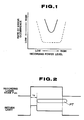
- the optimum laser power in maintaining a sufficiently low error rate of data recorded on an optical disc depends on the characteristics of the recording medium employed as the optical disc and may be fluctuated with temperatures or with the lapse of time. Some recording media may have only a narrow energy window, as shown by a solid line in Fig. 1, such that it is extremely difficult to set the laser power at a uniform value at the recording system.
- the servo system may be affected by the pits.
- the recording tracks on the optical recording medium are scanned by a recording laser beam emitted by the laser diode pulse-driven in accordance with the recording data during the record mode to form the pits to record the data
- a time lag ⁇ 0 of approximately 300 to 400 ns since the irradiation of the recording laser beam produced upon driving the laser diode with a recording pulse P WR corresponding to the recording data until start of formation of a pit PT on the recording track, as shown in Fig. 2, such that the detection output waveform of the recording laser beam irradiated on and reflected from the recording track is also modulated with the time lag ⁇ 0.
- the conventional servo system operating on the basis of the detection output of the reflected recording laser beam exhibits marked dependency on the pit pattern or record data formed on the recording tracks such that it becomes necessary to provide a wide dynamic range automatic gain control circuit in the servo system.
- an optical recording/reproducing apparatus making use of an optical recording medium having the modulation factor by the recording data signals equal to about 60%, which is almost as high as that of the compact disc, such as a write once type optical disc having a layer of an organic dye base optical recording medium
- the pattern of pits formed on the recording tracks during the recording mode may affect the servo system thus presenting a serious problem.
- the drive control means for a data recording light source of the recording medium in the light output setting control system of the present invention writes data on the optical recording medium with a light pulse as the light output of the light source is increased gradually.
- the light output of a data recording light source is automatically controlled to an optimum state on the real time basis on the basis of the detection output of light detection means detecting the volume of the light outputted from the light source and reflected by the recording medium, in such a manner that the volume of the reflected light from the recording medium reaches a predetermined value after the lapse of a predetermined time which should lapse since the light pulse output time from the light source until the formation of the recording pit on the recording medium by the light pulse.
- the rate of occurrence of errors in data recorded on the optical recording medium may be maintained at a lower level to enable optical recording with high reliability.
- the intensity of the return laser beam that is, the recording laser beam irradiated on and reflected back from the optical recording medium is detected and focusing or tracking error signals of the recording laser beam are formed on the basis of the detected intensity output of the return laser beam during the time the pits are actually formed on the recording medium by the laser beam to control the recording laser beam.
- the the control of the recording laser beam may be achieved satisfactorily without being affected by the pits formed in the optical recording medium.
- sub-data reproduction may be achieved without being affected by reading of the pits by sampling the return laser beam detection signals within the time before pit formation or the time during actual pit formation.
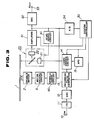
- FIG. 3 illustrates the construction of a recording/reproducing system of an optical disc recording/reproducing apparatus to which the present invention is applied and in which an optical disc 1 provided with a write-once type optical recording medium is rotationally driven at a constant linear velocity and recording tracks on the disc 1 are scanned with a laser beam of the optical head 20 to effect optical recording and/or reproducing of digital data of a predetermined data format on or from the disc.
- the optical head 20 of the optical disc recording/reproducing apparatus has enclosed therein such elements as a laser diode 21 driven by a laser driving circuit 14 to output a laser beam for digital data recording or reproducing and a photodiode 22 for detecting the laser beam radiated from the laser diode 21 and reflected by the optical disc 1.
- the recording tracks on the optical disc 1 are scanned by the laser beam outputted by the laser diode 21 to achieve data recording and/or reproducing on or from the recording tracks.
- the recording system of the optical disc recording/reproducing apparatus includes, above all, an encoder 12 for converting recording digital data D IN supplied from an input terminal 10 by way of an input/output interface 11 into a recording data string of a predetermined data format and a recording pulse generator 13 for applying recording pulses corresponding to the recording data string to the laser driving circuit 14.
- the laser diode 21 of the optical head 20 is driven with the recording pulses corresponding to the recording data string by the laser driving circuit 14 to record the digital data D IN on the recording tracks of the optical disc 1 as the above mentioned recording data string of the predetermined data format.
- the reproducing system of the optical disc recording/reproducing apparatus includes, above all, a decoder 32, to which detection outputs of the photodetector 22 of the optical head 20 are supplied by way of a detection amplifier 31 as RF detection signals.
- the detection outputs of the reflected light from the recording tracks on the optical disc 1, scanned by the laser light outputted from the laser diode 21 are subjected at the decoder 32 to a decoding operation corresponding to the encoding operation performed by the recording system to produce detection outputs which are issued by way of an output terminal 33.
- the optical disc recording/reproducing apparatus is also provided with a head servo circuit 41 supplied with detection outputs by the photodetector 22 of the optical head 20 from the detection amplifier 31. Focusing and tracking errors of the laser beam are detected at the head servo circuit 41 on the basis of the detection output, that is the RF detection signal, and the biaxial actuator, not shown, adapted for driving the objective lens of the optical head 20, is controlled on the basis of these error signals to effect head servo control inclusive of focusing servo and tracking servo control operations.
- the recording pulse generator 13, the laser driving circuit 14, the automatic power control(APC) circuit 15 controlling the output of the laser diode to a constant value and the detection amplifier 31 are controlled by a system controller 30 in accordance with operational modes proper to these devices.
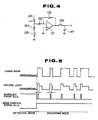
- the detection amplifier 31 is shown in detail in Fig. 4. That is, the detection amplifier 31 is comprised of an operational amplifier 131 having a non-inverting input terminal grounded, an inverting input terminal connected via a resistor 132 to the photodetector 22 of the optical head 20 via a resistor 132 and an output terminal connected to the inverting input terminal via a resistor 133.
- the point of junction between the photodetector 22 and the resistance 132 is grounded via a series circuit of a resistor 134 and a mode switch 135.
- the RF detection signal produced at the output terminal of the detection amplifier 31 is sampled by means of a sampling switch and held by a holding capacitor 137 before being outputted at the output terminal.
- the mode switch 135 and the sampling switch 136 are controlled by the system controller 30 in the following manner.
- the mode switch 135 is adapted to switch the input sensitivities of the detection amplifier 31 by a mode control signal S R /W from the system controller 30 depending on the operational mode and is opened and closed at the time of the detection mode and the recording mode, respectively.
- the sampling switch 136 is closed during the detection mode to sample the RF detection signal produced at an output terminal of the detection amplifier 31 with a sampling pulse s S/H formed from the recording pulse corresponding to the recording data string during the recording mode at the system controller 30 to hold the sampled values at the hold capacitor 137.
- the total detection output current i W by the photodetector 22 of the optical head 20 is introduced into the detection amplifier 31, after current division by the resistors 132, 134, so that a detection output voltage V W with R B being a resistance of the resistor 134, is outputted from the detection amplifier 31 via the sampling switch 136.
- the detection output voltage V W from the detection amplifier 31, that is the detection output by the photodetector 22 detecting the laser beam emitted by the laser diode 21 of the optical head 20 and reflected by the optical disc 1 is sampled during the recording mode by the sampling switch 136 within the range of a present time during which the pit is actually formed on the optical disc 1 by the laser beam.
- the head servo circuit 41 forms, on the basis of a detection output voltage V W (S/H) sampled by the sampling switch 136 and held by the holding capacitor 137, the aforementioned laser beam focusing and tracking error signals to perform the above mentioned head control operations.
- the head servo control operation by performing the head servo control operation by forming the laser beam focusing and tracking error signals on the basis of the detection output voltage V W (S/H) obtained upon sampling the detection output by the photodetector 22 within the range of the present time ⁇ during which the pit is actually formed on the optical disc 1 by the laser beam outputted from the optical head 20 during the recording mode, the aforementioned head servo control operations can be performed without being affected by the pits formed on the optical disc 1.
- the sampling switch 136 and the holding capacitor 137 are provided at an output stage of the detection amplifier 31 and the detection output by the photodetector 22 of the optical head 20 is sample-held within the preset time ⁇ , the head servo circuit 41 performing the laser beam focusing and tracking servo control operations on the basis of the sample-held output.
- the detection output by the photodetector 22 during the recording mode remains at the high signal level during the preset time since irradiation of the laser beam until the start of pit formation, as shown in Fig.
- peak holding means may be provided at an input stage to the head servo circuit 41, instead of providing sample-hold means at an output stage of the detection amplifier 31, and the peak holding means may be caused to operate during the recording mode, to produce the similar effect to that of the embodiment shown in Fig. 4.
- sample-holding means may be provided at the output stage of the error signal forming means, instead of providing sample-holding means at the output stage of the detection amplifier 31, as in the above described embodiment shown in Fig. 4, and the error signals formed on the basis of the detection output by the photodetector 22 may be sample-held by the sample holding means within the present time ⁇ to effect the laser beam focusing and tracking servo control operations.
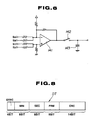
- Fig. 6 shows an embodiment of the head servo circuit 41 in which a sampling switch 142 and a holding capacitor 143 are provided in the output stage of an operational amplifier 141 forming the focusing error signal.
- the operational amplifier 141 is adapted to form the focusing error signal from four-part detector outputs S A , S B , S C and S D of the photodetector 22 of the optical head 20.
- the properties required of the circuit devices may be lower if the error signals are sample-held at the head servo circuit 41, instead of sample holding the RF detection signal at the output stage of the detection amplifier 31, as in the above described embodiment.
- the sub-data by the pre-grooves are detected on the basis of the detection output of the return laser beam during the preset time ⁇ which should elapse before the pit starts to be actually formed on the optical disc by the recording laser beam, or the detection output of the return laser beam within the time interval in which the pit is actually formed.
- pre-grooves or guide grooves 52 are previously formed with wobbling at the frequency, of, for example, 22.05 kHz, for tracking servo, and the absolute time code as the sub-data is modulated by the wobbling frequency of the pre-grooves 52.
- the absolute time code it is divided into 75 Hz frames for assuring interchangeability with the compact disc CD. Each frame is associated with 42-bit absolute time data or absolute time code DT shown in Fig. 8.
- This absolute time data DT is made up of a 4-bit sync code SYNC, minute, second and frame data MIN, SEC and FRM each represented by 8-bit BCD code, and 14-bit error check data CRC.
- the absolute time data DT is formed by the NRZ code having a bit rate of 3.15 k bps .
- This absolute time data is biphase mark modulated with 6.3 kHz bit clocks and the modulated signal is further frequency modulated to produce the wobbling signal which is the FM signal having a subcarrier frequency of 22.05 kHz.
- the light beam from the light source for preparation of the master disc is wobbled radially of the disc on the basis of the wobble signal for recording the absolute time code data DT of the CD format.
- This pre-groove recording format is called the absolute time in pregroove or ATIP format.
- the wobbling frequency of 22.05 kHz is selected to be affected to a laser extent by the recording data proper or EFM signal or by the servo signal.
- a photodetector 54 of an optical head 53 shown in Fig. 7 for detecting the return laser beam has four light-receiving sections 54A, 54B, 54C and 54D slit in the track direction and in the direction orthogonal thereto.
- the sum S AB of the outputs from the light receiving sections 54A and 54B and the outputs from the light receiving sections 54C and 54D is supplied to a subtractor 55 of Fig. 7.
- the difference of these signals S AB and S CD is taken at a subtractor 55 so that a push-pull output signal S PP is produced.
- This push-pull output signal S PP is supplied to a sample-hold circuit 57, to which a sampling pulse S SP from a sampling pulse generator 58 is also supplied and the output from the sample-hold circuit 57 is supplied to a band-pass filter 56 where the wobbling frequency component of 22.05 kHz is taken out.
- Fig. 10 shows examples of an EFM signal S EFM about to be recorded, a return laser beam L B and the sampling pulse S SP .
- the sampling pulse generator 58 is responsive to the inputting of the EFM signal S EFM to produce the sampling pulse S SP within the range of the preset delay time which should elapse before the pit starts to be formed.
- This sampling pulse S SP is transmitted to the sample-hold circuit 57 to sample-hold the push-pull output signal S PP .
- the output from the band-pass filter 56 is transmitted to an ATIP decoder 59 where the absolute time or ATIP data PT is read from the wobble signal and outputted.
- the absolute time data DT may be detected satisfactorily during the recording mode from the push-pull output of the return laser beam detection signal since the wobble signal component can be detected without being affected by the low frequency component due to reading the pits recorded on the disc 51.
- the wobble signal component may be detected without being affected by the low frequency components produced by reading the pits recorded on the disc 51 so that the absolute time data DT can be detected satisfactorily.
- the wobble signal component may be detected without being affected by the low frequency components produced by reading the pits.
- a light output setting and control device adapted for setting a laser output when recording data on an organic dye base optical recording medium in an optical disc recording/reproducing apparatus of the first or second embodiment will be hereinafter explained.
- FIG. 11 shows an arrangement of a recording/reproducing system of the optical disc recording/reproducing apparatus in which digital data are optically recorded and/or reproduced on or from an optical disc 61 formed by a write-once type optical recording medium in accordance with a prescribed data format, such as the data format meeting the CD standards, by rotating the disc 61 by a spindle motor 62 at a constant angular velocity for causing the optical head 80 to scan the recording tracks of the optical disc 61 by a laser beam.
- a prescribed data format such as the data format meeting the CD standards
- the operation of the recording pulse generating circuit 73 and the laser driving circuit 74 in the optical disc recording/reproducing apparatus is controlled by the system controller 90 to which the detection output from the photodetector 82 of the optical head 80 is supplied by way of the detection amplifier 91 and the analog-to-digital converter 94.
- the system controller 90 operates to apply a recording pulse of a predetermined period from the recording pulse generator 73 to the laser driving circuit 74 to pulse-drive the laser diode 81 of the optical head 80 to raise the laser power gradually a shown in Fig. 12 and at A in Fig. 13 to effect writing on a recording track in the table of contents or TOC(Table of Content) area of the optical disc which is not in use to perform the laser power setting operation in accordance with the control sequence shown in the from chart of Fig. 4.
- a recording pit P is formed after lapse of a predetermined time ⁇ since the output timing t0 of the recording laser pulse as shown at B in Fig. 12. Since the reflectivity is lowered at the site of the recording pit P, the return light volume from the optical disc 61 is modulated, as shown at C in Fig. 12.
- the laser diode 81 of the optical head 80 is pulse driven to raise the laser power gradually as shown at A in Fig. 13 to effect the recording on the optical disc 61, the return light volume from the optical disc 61 is increased gradually until it undergoes inflection with formation of the recording pit shown at C in Fig. 12 and at B in Fig. 13.
- the modulation factor of the return light volume becomes constant, as shown at C in Fig. 13.
- the return light volume from the optical disc 61 is sampled at a predetermined timing t1 before the lapse of the predetermined time since the output timing t0 of the recording laser pulse and at another predetermined timing t2 after the lapse of the predetermined time since the output timing t0.
- the laser driving circuit 74 is then controlled by the system controller 90 so that the laser power at this point proves to be an optimum recording laser power.
- a desired value MD t for the modulation factor MD for the return light volume by the recording pit on the disc 61 and a desired value Mt for the rate of change of the modulation factor M are set at a first step S1.
- the first sampling value D1 by the first sampling pulse SP1 taken.
- the second sampling value D2 by the second sampling pulse SP2 is taken.
- the laser diode 81 of the optical head 80 is pulse driven to raise the laser power gradually to effect recording on the disc 61.
- the program proceeds to the tenth step S10 at which the prevailing laser power P WR is set as the optimum recording laser power P WROP to complete the recording power setting operation.
- the system controller 90 controls the operation of the laser driving circuit 74 so that the recording laser power proves to be the aforementioned optimum recording laser power P WROP during the recording mode and so that the read-out laser power P RE becomes lower than the optimum recording laser power P WROP during the reproducing mode.
- the recording laser power setting control operation is performed in the above embodiment with the use of the TOC area of the optical disc 61, it is also possible to control the laser driving circuit 74 by the system controller 90 by sampling the return light volume from the disc 61 with the sampling pulses SP1, SP2 during the recording operation on the recording track to maintain the optimum recording laser power P WROP at all times from the ratio of the first sampling value D1 to the second sampling value D2.
Landscapes
- Physics & Mathematics (AREA)
- Optics & Photonics (AREA)
- Optical Recording Or Reproduction (AREA)
- Laser Beam Printer (AREA)
- Optical Head (AREA)
- Facsimile Scanning Arrangements (AREA)
Applications Claiming Priority (6)
| Application Number | Priority Date | Filing Date | Title |
|---|---|---|---|
| JP301546/88 | 1988-11-29 | ||
| JP63301546A JP2764965B2 (ja) | 1988-11-29 | 1988-11-29 | 光出力設定制御装置及び光出力設定制御方法 |
| JP33490688 | 1988-12-29 | ||
| JP334906/88 | 1988-12-29 | ||
| JP83693/89 | 1989-03-31 | ||
| JP1083693A JP2785311B2 (ja) | 1988-12-29 | 1989-03-31 | 記録レーザビームの制御方法、制御装置、検出方法および検出装置 |
Publications (3)
| Publication Number | Publication Date |
|---|---|
| EP0371880A2 true EP0371880A2 (fr) | 1990-06-06 |
| EP0371880A3 EP0371880A3 (fr) | 1992-03-11 |
| EP0371880B1 EP0371880B1 (fr) | 1995-01-18 |
Family
ID=27304303
Family Applications (1)
| Application Number | Title | Priority Date | Filing Date |
|---|---|---|---|
| EP89403314A Expired - Lifetime EP0371880B1 (fr) | 1988-11-29 | 1989-11-29 | Méthode et appareil pour la commande et détection d'un laser utilisé pour enregistrement |
Country Status (6)
| Country | Link |
|---|---|
| US (1) | US5126994A (fr) |
| EP (1) | EP0371880B1 (fr) |
| KR (1) | KR100233412B1 (fr) |
| AT (1) | ATE117454T1 (fr) |
| AU (1) | AU628885B2 (fr) |
| DE (1) | DE68920716T2 (fr) |
Cited By (8)
| Publication number | Priority date | Publication date | Assignee | Title |
|---|---|---|---|---|
| EP0478202A1 (fr) * | 1990-09-27 | 1992-04-01 | International Business Machines Corporation | Calibrage d'un système de mémorisation de données concernant un disque amovible de mémorisation de données dans le système |
| EP0559391A2 (fr) * | 1992-03-03 | 1993-09-08 | Canon Kabushiki Kaisha | Appareil d'enregistrement et de reproduction magnéto-optique |
| EP0714092A1 (fr) * | 1994-11-22 | 1996-05-29 | Sony Corporation | Appareil d'enregistrement/lecture d'information |
| EP0729136A1 (fr) * | 1995-02-27 | 1996-08-28 | NEC Corporation | Procédé et dispositif d'enregistrement et de lecture de donées optiques utilisant un milieu optique de changement de phase |
| US5844883A (en) * | 1996-03-25 | 1998-12-01 | Sony Corporation | Recording medium, optical disk apparatus and method of information recording |
| EP0936602A2 (fr) * | 1998-02-13 | 1999-08-18 | Yamaha Corporation | Technique d'enregistrement sur un disque optique capable de former des creux centrés avec précision sur la piste, et technique de réglage de l'équilibre d'asservissement pour l'enregistrement sur un disque optique |
| EP1343151A1 (fr) * | 2000-12-06 | 2003-09-10 | Sony Corporation | Appareil et procede d'enregistrement |
| WO2005069286A1 (fr) * | 2004-01-13 | 2005-07-28 | Koninklijke Philips Electronics N.V. | Procede et appareil pour la commande d'un signal d'ecriture dans un systeme de disque optique |
Families Citing this family (23)
| Publication number | Priority date | Publication date | Assignee | Title |
|---|---|---|---|---|
| NL9000150A (nl) * | 1990-01-22 | 1991-08-16 | Philips Nv | Werkwijze en inrichting voor het aanbrengen van een patroon van gebiedjes met veranderde optische eigenschappen in een registratiedrager. |
| JP2797733B2 (ja) * | 1990-03-14 | 1998-09-17 | 松下電器産業株式会社 | 光学情報記録部材の記録方法 |
| US5537379A (en) | 1991-05-10 | 1996-07-16 | Discovision Associates | Optical data storage and retrieval system and method |
| JP3336629B2 (ja) * | 1992-06-09 | 2002-10-21 | ソニー株式会社 | 光ディスク装置および光ピックアップの移動方法 |
| US5572502A (en) * | 1993-09-28 | 1996-11-05 | Hitachi, Ltd. | Optical disk apparatus |
| US5495466A (en) * | 1994-01-10 | 1996-02-27 | Eastman Kodak Company | Write verification in an optical recording system by sensing mark formation while writing |
| JPH0973637A (ja) | 1995-09-06 | 1997-03-18 | Hitachi Ltd | 光ディスク信号処理装置 |
| US5726965A (en) * | 1996-02-29 | 1998-03-10 | Eastman Kodak Company | Intersymbol interference detection in an optical recording system using a reflected write signal |
| KR100438565B1 (ko) * | 1996-09-19 | 2004-08-25 | 엘지전자 주식회사 | 광기록장치의기록광원제어방법 |
| US5978334A (en) * | 1997-10-24 | 1999-11-02 | Eastman Kodak Company | Sampling timing for a reflected write signal |
| US6151290A (en) * | 1998-02-05 | 2000-11-21 | Sony Corporation | Inexpensive safe light beam recorder |
| DE69917291T2 (de) * | 1998-08-20 | 2004-09-09 | Matsushita Electric Industrial Co., Ltd., Kadoma | Laserleistungskontrollvorrichtung und optisches plattengerät |
| GB2362280A (en) * | 2000-05-12 | 2001-11-14 | Roke Manor Research | Optical pulse shaping apparatus |
| JP3800112B2 (ja) * | 2002-03-07 | 2006-07-26 | ヤマハ株式会社 | 光ディスク記録方法およびその装置 |
| JP3931774B2 (ja) * | 2002-09-20 | 2007-06-20 | 松下電器産業株式会社 | 欠陥検出装置 |
| JP2004206803A (ja) * | 2002-12-25 | 2004-07-22 | Teac Corp | 光ディスク装置 |
| JP2004220663A (ja) * | 2003-01-10 | 2004-08-05 | Pioneer Electronic Corp | 光ピックアップ装置、光ビーム出射制御方法、並びに、光ビーム出射制御プログラムおよびそれを記録した記録媒体 |
| JP4209205B2 (ja) * | 2003-01-10 | 2009-01-14 | パイオニア株式会社 | 光ビーム出力制御装置、光ピックアップ装置、光ビーム出射制御方法、並びに、光ビーム出射制御プログラムおよびそれを記録した記録媒体 |
| WO2004100139A1 (fr) * | 2003-05-08 | 2004-11-18 | Nec Corporation | Tete optique, procede de fabrication et dispositif d'enregistrement/de reproduction d'information optique |
| JP2007179700A (ja) * | 2005-12-28 | 2007-07-12 | Toshiba Corp | レーザ駆動電流制御回路および光ディスク装置 |
| JP2012014777A (ja) | 2010-06-30 | 2012-01-19 | Sony Corp | 制御装置、制御方法および制御プログラム |
| EP2793230A4 (fr) | 2011-12-13 | 2016-04-20 | Panasonic Corp | Dispositif d'enregistrement/de reproduction optique |
| JP5938717B2 (ja) | 2012-01-11 | 2016-06-22 | パナソニックIpマネジメント株式会社 | 光記録再生装置 |
Citations (3)
| Publication number | Priority date | Publication date | Assignee | Title |
|---|---|---|---|---|
| US4283785A (en) * | 1978-04-28 | 1981-08-11 | Hitachi, Ltd. | Optical information recording apparatus |
| EP0035236A1 (fr) * | 1980-02-29 | 1981-09-09 | Kabushiki Kaisha Toshiba | Dispositif de commande asservie d'alignement sur une piste |
| EP0265695A2 (fr) * | 1986-09-30 | 1988-05-04 | Sony Corporation | Appareil d'enregistrement |
Family Cites Families (10)
| Publication number | Priority date | Publication date | Assignee | Title |
|---|---|---|---|---|
| US4562567A (en) * | 1982-11-12 | 1985-12-31 | North American Philips Corporation | Apparatus for controlling the write beam in an optical data recording system |
| US4707816A (en) * | 1985-03-29 | 1987-11-17 | Hitachi, Ltd. | Method and apparatus for composite wobbled and push-pull tracking servo system |
| US4959823A (en) * | 1985-07-30 | 1990-09-25 | Laser Magnetic Storage International Company | Tracking and seeking system for use with an optical record carrier having a wobbled track format |
| JPS6267731A (ja) * | 1985-09-20 | 1987-03-27 | Fujitsu Ltd | 光記録再生方法及び光記録再生装置 |
| JP2810035B2 (ja) * | 1986-08-22 | 1998-10-15 | 株式会社日立製作所 | 光学的記録再生方法 |
| EP0278006B1 (fr) * | 1986-08-25 | 1994-05-11 | Sony Corporation | Dispositif a disque et support d'enregistrement en forme de disque |
| KR910003460B1 (ko) * | 1987-02-12 | 1991-05-31 | 가부시기가이샤 히다찌세이사꾸쇼 | 광학식 정보기록 장치 |
| US4873680A (en) * | 1987-03-13 | 1989-10-10 | Laserdrive Ltd. | Apparatus and method for detecting and compensating for pit extension in an optical disk recording system |
| NL8800223A (nl) * | 1987-04-21 | 1988-11-16 | Philips Nv | Systeem voor het registreren van een informatiesignaal, alsmede een registratiedrager en registratieinrichting voor toepassing in het systeem. |
| DE3888565T2 (de) * | 1987-04-28 | 1994-10-20 | Sharp Kk | Aufzeichnungs- und Wiedergabegerät. |
-
1989
- 1989-11-21 US US07/439,584 patent/US5126994A/en not_active Expired - Lifetime
- 1989-11-24 AU AU45544/89A patent/AU628885B2/en not_active Expired
- 1989-11-29 KR KR1019890017385A patent/KR100233412B1/ko not_active IP Right Cessation
- 1989-11-29 EP EP89403314A patent/EP0371880B1/fr not_active Expired - Lifetime
- 1989-11-29 AT AT89403314T patent/ATE117454T1/de not_active IP Right Cessation
- 1989-11-29 DE DE68920716T patent/DE68920716T2/de not_active Expired - Lifetime
Patent Citations (3)
| Publication number | Priority date | Publication date | Assignee | Title |
|---|---|---|---|---|
| US4283785A (en) * | 1978-04-28 | 1981-08-11 | Hitachi, Ltd. | Optical information recording apparatus |
| EP0035236A1 (fr) * | 1980-02-29 | 1981-09-09 | Kabushiki Kaisha Toshiba | Dispositif de commande asservie d'alignement sur une piste |
| EP0265695A2 (fr) * | 1986-09-30 | 1988-05-04 | Sony Corporation | Appareil d'enregistrement |
Cited By (20)
| Publication number | Priority date | Publication date | Assignee | Title |
|---|---|---|---|---|
| US5134602A (en) * | 1990-09-27 | 1992-07-28 | International Business Machines Corporation | Calibrating optical disk recorders to some parameters during disk spin up while deferring calibration of other parameters |
| EP0478202A1 (fr) * | 1990-09-27 | 1992-04-01 | International Business Machines Corporation | Calibrage d'un système de mémorisation de données concernant un disque amovible de mémorisation de données dans le système |
| EP0559391A2 (fr) * | 1992-03-03 | 1993-09-08 | Canon Kabushiki Kaisha | Appareil d'enregistrement et de reproduction magnéto-optique |
| EP0559391A3 (fr) * | 1992-03-03 | 1993-10-13 | Canon Kabushiki Kaisha | Appareil d'enregistrement et de reproduction magnéto-optique |
| US5398227A (en) * | 1992-03-03 | 1995-03-14 | Canon Kabushiki Kaisha | Magnetooptical recording reproducing apparatus and method for determining the power of an irradiating light beam on the basis of a detected amplitude of a recording signal |
| EP0714092A1 (fr) * | 1994-11-22 | 1996-05-29 | Sony Corporation | Appareil d'enregistrement/lecture d'information |
| US5742578A (en) * | 1994-11-22 | 1998-04-21 | Sony Corporation | Information recording and reproducing apparatus using light beam modulation on a spiral guide groove disk |
| AU692938B2 (en) * | 1994-11-22 | 1998-06-18 | Sony Corporation | Information recording and reproducing apparatus |
| CN1080917C (zh) * | 1994-11-22 | 2002-03-13 | 索尼公司 | 信息记录和再现装置 |
| US5946280A (en) * | 1995-02-27 | 1999-08-31 | Nec Corporation | Method for verifying accuracy of data written on a phase transition optical disk during the writing operation |
| EP0729136A1 (fr) * | 1995-02-27 | 1996-08-28 | NEC Corporation | Procédé et dispositif d'enregistrement et de lecture de donées optiques utilisant un milieu optique de changement de phase |
| US5717673A (en) * | 1995-02-27 | 1998-02-10 | Nec Corporation | Method and apparatus for verifying accuracy of data written on a phase transition optical disk during the writing operation |
| US5844883A (en) * | 1996-03-25 | 1998-12-01 | Sony Corporation | Recording medium, optical disk apparatus and method of information recording |
| EP0936602A3 (fr) * | 1998-02-13 | 2002-02-20 | Yamaha Corporation | Technique d'enregistrement sur un disque optique capable de former des creux centrés avec précision sur la piste, et technique de réglage de l'équilibre d'asservissement pour l'enregistrement sur un disque optique |
| EP0936602A2 (fr) * | 1998-02-13 | 1999-08-18 | Yamaha Corporation | Technique d'enregistrement sur un disque optique capable de former des creux centrés avec précision sur la piste, et technique de réglage de l'équilibre d'asservissement pour l'enregistrement sur un disque optique |
| US6643239B2 (en) | 1998-02-13 | 2003-11-04 | Yamaha Corporation | Optical disk recording technique capable of forming pits accurately centered on track and servo-balance adjusting technique for optical disk recording |
| EP1343151A1 (fr) * | 2000-12-06 | 2003-09-10 | Sony Corporation | Appareil et procede d'enregistrement |
| EP1343151A4 (fr) * | 2000-12-06 | 2006-02-01 | Sony Corp | Appareil et procede d'enregistrement |
| US7324414B2 (en) | 2000-12-06 | 2008-01-29 | Sony Corporation | Apparatus and method of optical disk recording while detecting vibration |
| WO2005069286A1 (fr) * | 2004-01-13 | 2005-07-28 | Koninklijke Philips Electronics N.V. | Procede et appareil pour la commande d'un signal d'ecriture dans un systeme de disque optique |
Also Published As
| Publication number | Publication date |
|---|---|
| DE68920716T2 (de) | 1995-06-08 |
| KR900008493A (ko) | 1990-06-04 |
| KR100233412B1 (ko) | 1999-12-01 |
| EP0371880A3 (fr) | 1992-03-11 |
| AU4554489A (en) | 1990-06-07 |
| ATE117454T1 (de) | 1995-02-15 |
| EP0371880B1 (fr) | 1995-01-18 |
| US5126994A (en) | 1992-06-30 |
| DE68920716D1 (de) | 1995-03-02 |
| AU628885B2 (en) | 1992-09-24 |
Similar Documents
| Publication | Publication Date | Title |
|---|---|---|
| EP0371880B1 (fr) | Méthode et appareil pour la commande et détection d'un laser utilisé pour enregistrement | |
| EP0469727B1 (fr) | Appareil d'enregistrement/de reproduction de disque optique | |
| US5490127A (en) | Asymmetry detector for use in an optical recording and reproducing device | |
| JPS6267731A (ja) | 光記録再生方法及び光記録再生装置 | |
| US5309424A (en) | Optical recording apparatus recording beam controlled in response to reduced light level reflected between successively formed pits | |
| EP0414517B1 (fr) | Appareil et méthode d'enregistrement pour disque optique | |
| JP2785311B2 (ja) | 記録レーザビームの制御方法、制御装置、検出方法および検出装置 | |
| JP2726470B2 (ja) | 記録媒体並びに光学式読取装置 | |
| JP2764965B2 (ja) | 光出力設定制御装置及び光出力設定制御方法 | |
| US7330415B2 (en) | Optical record carrier recording method and recording apparatus | |
| JP3282575B2 (ja) | 光記録装置 | |
| JP2605421B2 (ja) | 光ディスク記録装置 | |
| US7362670B2 (en) | Optical disc drive | |
| JP3058159B2 (ja) | 光記録装置及び光記録方法 | |
| JPH0312375B2 (fr) | ||
| JP3035400B2 (ja) | 光学式再生装置 | |
| JP2785207B2 (ja) | 光書き込み制御装置 | |
| JPH1074330A (ja) | 光記録装置 | |
| JPH08180496A (ja) | 光磁気ディスクの記録方法、再生方法及び再生装置 | |
| JP3243735B2 (ja) | 光ディスク再生装置 | |
| JPH07334918A (ja) | 記録領域検出回路 | |
| JP2003223717A (ja) | 光記録装置 | |
| JPH0312377B2 (fr) | ||
| JPH08180498A (ja) | 光磁気ディスクの再生装置及び記録/再生装置 | |
| JPH0644562A (ja) | 光ディスク記録再生方法及びその装置 |
Legal Events
| Date | Code | Title | Description |
|---|---|---|---|
| PUAI | Public reference made under article 153(3) epc to a published international application that has entered the european phase |
Free format text: ORIGINAL CODE: 0009012 |
|
| AK | Designated contracting states |
Kind code of ref document: A2 Designated state(s): AT DE FR GB IT |
|
| PUAL | Search report despatched |
Free format text: ORIGINAL CODE: 0009013 |
|
| AK | Designated contracting states |
Kind code of ref document: A3 Designated state(s): AT DE FR GB IT |
|
| 17P | Request for examination filed |
Effective date: 19920907 |
|
| 17Q | First examination report despatched |
Effective date: 19930512 |
|
| GRAA | (expected) grant |
Free format text: ORIGINAL CODE: 0009210 |
|
| AK | Designated contracting states |
Kind code of ref document: B1 Designated state(s): AT DE FR GB IT |
|
| REF | Corresponds to: |
Ref document number: 117454 Country of ref document: AT Date of ref document: 19950215 Kind code of ref document: T |
|
| REF | Corresponds to: |
Ref document number: 68920716 Country of ref document: DE Date of ref document: 19950302 |
|
| ET | Fr: translation filed | ||
| ITF | It: translation for a ep patent filed |
Owner name: SOCIETA' ITALIANA BREVETTI S.P.A. |
|
| PLBE | No opposition filed within time limit |
Free format text: ORIGINAL CODE: 0009261 |
|
| STAA | Information on the status of an ep patent application or granted ep patent |
Free format text: STATUS: NO OPPOSITION FILED WITHIN TIME LIMIT |
|
| 26N | No opposition filed | ||
| REG | Reference to a national code |
Ref country code: GB Ref legal event code: IF02 |
|
| PGFP | Annual fee paid to national office [announced via postgrant information from national office to epo] |
Ref country code: DE Payment date: 20081127 Year of fee payment: 20 |
|
| PGFP | Annual fee paid to national office [announced via postgrant information from national office to epo] |
Ref country code: AT Payment date: 20081112 Year of fee payment: 20 |
|
| PGFP | Annual fee paid to national office [announced via postgrant information from national office to epo] |
Ref country code: IT Payment date: 20081126 Year of fee payment: 20 |
|
| PGFP | Annual fee paid to national office [announced via postgrant information from national office to epo] |
Ref country code: FR Payment date: 20081112 Year of fee payment: 20 |
|
| PGFP | Annual fee paid to national office [announced via postgrant information from national office to epo] |
Ref country code: GB Payment date: 20081126 Year of fee payment: 20 |
|
| REG | Reference to a national code |
Ref country code: GB Ref legal event code: PE20 Expiry date: 20091128 |
|
| PG25 | Lapsed in a contracting state [announced via postgrant information from national office to epo] |
Ref country code: GB Free format text: LAPSE BECAUSE OF EXPIRATION OF PROTECTION Effective date: 20091128 |