EP0265695A2 - Appareil d'enregistrement - Google Patents
Appareil d'enregistrement Download PDFInfo
- Publication number
- EP0265695A2 EP0265695A2 EP87114288A EP87114288A EP0265695A2 EP 0265695 A2 EP0265695 A2 EP 0265695A2 EP 87114288 A EP87114288 A EP 87114288A EP 87114288 A EP87114288 A EP 87114288A EP 0265695 A2 EP0265695 A2 EP 0265695A2
- Authority
- EP
- European Patent Office
- Prior art keywords
- signal
- predetermined frequency
- recording medium
- disc
- frequency
- Prior art date
- Legal status (The legal status is an assumption and is not a legal conclusion. Google has not performed a legal analysis and makes no representation as to the accuracy of the status listed.)
- Granted
Links
Images


Classifications
-
- G—PHYSICS
- G11—INFORMATION STORAGE
- G11B—INFORMATION STORAGE BASED ON RELATIVE MOVEMENT BETWEEN RECORD CARRIER AND TRANSDUCER
- G11B7/00—Recording or reproducing by optical means, e.g. recording using a thermal beam of optical radiation by modifying optical properties or the physical structure, reproducing using an optical beam at lower power by sensing optical properties; Record carriers therefor
- G11B7/24—Record carriers characterised by shape, structure or physical properties, or by the selection of the material
- G11B7/2407—Tracks or pits; Shape, structure or physical properties thereof
- G11B7/24085—Pits
-
- C—CHEMISTRY; METALLURGY
- C22—METALLURGY; FERROUS OR NON-FERROUS ALLOYS; TREATMENT OF ALLOYS OR NON-FERROUS METALS
- C22B—PRODUCTION AND REFINING OF METALS; PRETREATMENT OF RAW MATERIALS
- C22B11/00—Obtaining noble metals
- C22B11/08—Obtaining noble metals by cyaniding
-
- G—PHYSICS
- G11—INFORMATION STORAGE
- G11B—INFORMATION STORAGE BASED ON RELATIVE MOVEMENT BETWEEN RECORD CARRIER AND TRANSDUCER
- G11B27/00—Editing; Indexing; Addressing; Timing or synchronising; Monitoring; Measuring tape travel
- G11B27/10—Indexing; Addressing; Timing or synchronising; Measuring tape travel
- G11B27/19—Indexing; Addressing; Timing or synchronising; Measuring tape travel by using information detectable on the record carrier
- G11B27/28—Indexing; Addressing; Timing or synchronising; Measuring tape travel by using information detectable on the record carrier by using information signals recorded by the same method as the main recording
- G11B27/30—Indexing; Addressing; Timing or synchronising; Measuring tape travel by using information detectable on the record carrier by using information signals recorded by the same method as the main recording on the same track as the main recording
- G11B27/3027—Indexing; Addressing; Timing or synchronising; Measuring tape travel by using information detectable on the record carrier by using information signals recorded by the same method as the main recording on the same track as the main recording used signal is digitally coded
- G11B27/3036—Time code signal
-
- G—PHYSICS
- G11—INFORMATION STORAGE
- G11B—INFORMATION STORAGE BASED ON RELATIVE MOVEMENT BETWEEN RECORD CARRIER AND TRANSDUCER
- G11B7/00—Recording or reproducing by optical means, e.g. recording using a thermal beam of optical radiation by modifying optical properties or the physical structure, reproducing using an optical beam at lower power by sensing optical properties; Record carriers therefor
- G11B7/08—Disposition or mounting of heads or light sources relatively to record carriers
- G11B7/09—Disposition or mounting of heads or light sources relatively to record carriers with provision for moving the light beam or focus plane for the purpose of maintaining alignment of the light beam relative to the record carrier during transducing operation, e.g. to compensate for surface irregularities of the latter or for track following
-
- G—PHYSICS
- G11—INFORMATION STORAGE
- G11B—INFORMATION STORAGE BASED ON RELATIVE MOVEMENT BETWEEN RECORD CARRIER AND TRANSDUCER
- G11B7/00—Recording or reproducing by optical means, e.g. recording using a thermal beam of optical radiation by modifying optical properties or the physical structure, reproducing using an optical beam at lower power by sensing optical properties; Record carriers therefor
- G11B7/24—Record carriers characterised by shape, structure or physical properties, or by the selection of the material
Definitions
- the invention relates to a recording apparatus for forming a track onto an optical disk and a recording method for forming the same and, more particularly, to an apparatus for recording an absolute time code, for instance, as a pregroove in the case of pregroove formation.
- the three-spot system maintains a relationship in which two subbeam spots are positioned on both sides of a track and a main beam spot is positioned at the center of the track. Reflection light from the two subbeams is led to a pair of optical sensors arranged on both sides of a main sensor so that a tracking error can be detected from a difference output of the pair of optical sensors.
- a beam is irradiated at the center of the track, reflection light therefrom is detected at a two-division optical sensor, and a difference output of two optical sensor elements due to deviation of diffracted light is detected as a tracking error.
- the wobbling system there are a system for detecting a tracking error from an output of coherent detection of a reproduced signal and a signal for oscillating a reproduced beam by giving a meander to the reproduced beam and a system for wobbling the track side at a predetermined frequency.
- the wobbling is done by a sinewave signal of 22.05 [kHz], for instance.
- a rotation system of an optical disk these are a CAV (constance angular velocity system) and a CLV (constant linear velocity system).
- the CLV can improve the density of data recording as compared with the CAV, while a CLV servo for controlling the rotation speed depending on a position in the radius direction of the optical disk is needed.
- the position in the radius direction of the disk is detected by a position detector such as potentiometer cooperating with an optical head.
- the use of the position detector such as a potentiometer invites a cost increase and does not attain correct position detection necessarrily. It is desirable that the position of the optical head on the optical disk can be detected from a reproduced signal without separately providing the position detector.
- the recording of the time code in a data track itself tends to decrease an effective data amount capable of recording on a single disk.
- the use of a PSK modulation can be considered.
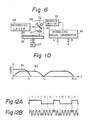
- the PSK modulation develops a modulated signal shown at B of Fig. 12 and having phases corresponding to "1" and "0" of data shown at A of Fig. 12, respectively.
- the phases of the modulated signal become discontinuous.
- An object of the invention is, therefore, to provide a recording apparatus and a recording method capable of providing position information by applying a signal containing another information signal such as time code as a deflection control signal for forming a wobbling track for tracking error detection without employing any position detector and increasing data redundancy.
- the recording apparatus comprises a deflection device for deviating a recording beam from a light source in an radius direction of said disk-shape recording medium; and a deflection-control signal generating device.
- the deflection control signal is a combined signal composed of the superimposition of a first signal having a predetermined frequency and a second signal having a lower frequency than said predetermined frequency. More specifically, the first signal is a wobbling signal, the second signal is absolute time information, and the track is a pregroove
- a combination signal which is the superimposition of the first signal and the second signal is used as a deflection control signal.
- the first signal is employed for the detection of a tracking error.
- the signal is a signal of 22.05 [kHz].
- the second signal is an absolute time code of a CD format varying at a lower frequency, for instance, at 75 [Hz] than 22.05 [kHz]. Since the frequency of the second signal is very low as compared with the first signal, the deflection control signal has a predetermined frequency of the first signal as a whole even if the second signal is superimposed.
- a time code is recorded in the pregroove itself.
- an absolute time code adopted in a CD compact disk
- the absolute time code is in one-to-one correspondence to a scanning position of a head (pickup) of the optical disk and gives not only information of a disk diameter at the time of rotating the optical disk by a CLV (constant linear velocity) system but also address information at the time of data access.
- a signal of 588 bits is recorded as a frame in channel bits, and a frame frequency at a pre-determined linear velocity is 7.35 [kHz].
- spaces user's bits or subcodes
- the subcode is made up of eight independent bits (called "PQRSTUVW"), and two channels of P and Q are presently employed. Said eight independent bits are inserted into one frame by EFM modulation.
- Each channel of the subcode is composed of by making 98 bits contained in 98 frames, respectively, one block.
- an absolute time code "AMIN”, "ASEC”, and "AFRAME” is inserted.
- Each of the minute, second and frame of the absolute time code can be represented by two digits of the BCD code.
- the minute and second vary between (00 ⁇ 59), and the frame changes between (0 ⁇ 74) using a total of six characters of the BCD code.
- EFM Eight to Fourteen Modulation for channel coding converts a signal of 8 bits per symbol into a 14-bit signal according to a predetermined rule. With the EFM, the occupied frequency band becomes narrow, and clock components increase to reduce direct current components.
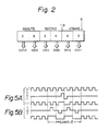
- the data bits "0" and “1" of one data bit and the preamble are modulated, respectively at shown B of Fig. 4.
- the data bits "0" are modulated into a sequence ("0" sequence) in which 24 samples take a high level and a low level alternately.
- the 12-th sample of the 24 samples has a high level changed from a low level
- the 13-th sample has a low level changed from a high level
- the other samples are modulated into a sequence ("1" sequence) similar to the data bits "0”.
- the preamble is made to a pattern having a high level and a low level alternately every three samples.
- the data bits "0" are modulated into a DC-free sequence.
- This sequence has a repetition frequency of 21.05 [kHz] and contains a sinewave component for tracking control.
- the "1" sequence corresponding to the data bits "1” is a DC-free sequence similarly and its run length is limited to two samples.
- the "0" sequence corresponding to the data bits "0” is desirable as compared with the "1” sequence in terms of the sinewave component for tracking control. With respect to the absolute time code, the "0" sequence is a more desirable pattern that the "1” sequence, since the length of "0” continuation is long as compared with "1".
- the sequence corresponding to the preamble is DC-free and is generated once every (1/75) second.
- a method for actually producing the "1" sequence and the preamble sequence will be described with reference to Fig. 5.
- 24 samples of the "1" sequence is developed by the addition of a ternary signal, which is (+1) at the 12-th sample and (-1) at the 13-th sample to the "0" sequence as shown at A of Fig. 5.
- a 12-sample sequence corresponding to the preamble is developed by the addition of a signal, which is (+1) at the 8th sample and the 14-th sample, respectively and (-1) at the 11-th sample and the 17-th sample, respectively, to the "0" sequence as shown at B of Fig. 5.
- Fig. 1 one example of the modulation circuit, which modulates "0" or "1" of data bits into a 24-sample sequence of a predetermined pattern, is shown in Fig. 1.
- Fig. 1 is an input terminal to which a frame pulse A of a frame frequency 75 [Hz] is given.
- 2 is an input terminal to which a clock pulse B of 44.1 [kHz] is given.
- the period of the clock pulse B is indicated by T.
- a and B of Fig. 3 show the frame pulse A and the clock pulse B, respectively.
- the clock pulse B is used as inputs of a T flip-flop 3 and a duodecimal counder 4.
- a "0" sequence C with the period 2T shown at C of Fig. 3 is generated from the T flip-flop 3.
- To the T flip-flop 3 and the duodecimal counter 4 is supplied the frame pulse A as a clear input.
- the frame pulse A is supplied as a set input of the SR flip-flop 5, and as its reset input the carry output of the duodecimal counter 4 is given. For this reason, a pulse signal D, which takes a low level for a period from the frame pulse A to 12T, is produced at an output terminal of the SR flip-flop 5 as shown at D of Fig. 3.
- the pulse signal D is supplied to an AND gate 6 and an edge detector 7.
- the clock pulse B is given to the AND gate 6 and to the 24-notated counter 8 via the AND gate 6.
- the 24-notated counter 8 is cleared by a carry output E of the 24-notated counter 8, and the carry output E is given to an adder 9.
- the carry output E of the 24-notated counter 8 is generated every 24T after the pulse signal D takes a high level as shown at E of Fig. 3. Also, a pulse signal, which is in synchronism with a leading edge of the pulse signal D, is produced from the edge detector 7 and supplied to the adder 9. A pulse signal I from the adder 9 is generated every 24T after the 12T-period of the preamble as shown as I of Fig. 3.
- the parallel output data of the 24-notated counter 8 is supplied to a decorder 10.
- the output signal of the decoder 10 produced when the content of the 24-notated counter 8 is 12, is given to a (1) generator 11, while the output signal of the decoder 10 produced when the content of the 24-notated counter 8 is 13, is given to a (-1) generator 12.
- a pulse signal F with a "1" level is generated from the (1) generator 11, wherease a pulse signal G with a (-1) level is generated from the (-1) generator 12 as shown at G of Fig. 3.
- These pulse signals F and G are added up at an adder 13.
- the output signal of the adder 13 is given to an adder 14. Since the "0" sequence C from the T flip-flop 3 is supplied to the adder 14, the output signal of the adder 14 becomes a "1" sequence.
- the switch circuit 15 is controlled by a switch signal K from a switch signal generator 18, and data from the switch circuit 15 is supplied to a combination circuit 20.
- the combination circuit 20 adds a preamble of 12 samples every 588 samples.
- the preamble is developed by a ternary logical signal generator 16 and an adder 17.
- the ternary logical signal generator 16 generates a ternary pulse signal H of (0100 - 100100 - 10) in synchronism with the frame pulse A as shown at H of Fig. 3.
- the pulse signal H and the "0" sequence C are given to the adder 17, and the preamble is produced from the adder 17.
- a modulated sequence is obtained at an output terminal 21 of the combination circuit 20.
- FIG. 19 is an absolute time counter for producing an absolute time code of a CD format on the basis of the frame pulse A.
- Fig. 2 shows a construction of the absolute time counter 19, and each of the frame, second and minute is made up of two BCD.
- Fig. 2 illustrates the example of ⁇ 28 minutes 34 seconds 63 frames ⁇ . In this case, six BCD characters ⁇ (0010) (1000) (0011) (0100) (0110) (0011) ⁇ are generated.
- the absolute time code from the absolute time counter 19 is sent to the switching signal generator 18.
- Each data bit of the absolute time code is taken into the switching signal generator 18 in synchronism with a pulse signal I as shown at J of Fig. 3.
- a switching signal K K of Fig.
- FIG. 6 A cutting system for forming a pregroove on an optical disk is shown in Fig. 6.
- 25 shows a glass disk, and a photoresist 26 is coated on the glass disk 25.
- the glass disk 25 is rotated by a spindle motor 27 at CLV.
- 28 is a recording laser, for instance, an argon-ion laser.
- a laser beam from the recording laser 28 is reflected from a glavanomirror 30 of an optical head 29 circled by a broken line and irradiated into the photoresist 26 through an object lens 31.
- the rotation of the galvanomirror 30 by a galvanomotor 32 wobbles the laser beam in the diameter direction.
- a drive signal from a mirror driver 33 is given to the galvanomotor 32.
- a wobbling signal from a wobbling signal generator 34 is supplied to the mirror driver.
- the wobbling generator 34 is composed of the above-mentioned modulation circuit and a filter for band restriction.
- a spiral and wobbled pregroove is exposed onto the photoresist 26 by the laser beam.
- Fig. 7 shows a glass master optically cut, and a concave portion corresponding to the pregroove is formed onto the photoresist 26 through development as shown by .
- An aluminium 35 is then vapor-deposited on the photoresist 26 ( ).
- nickel plating 36 is applied ( ), and a metal master is formed by removing the nickel plating 36 ( ).
- a stamper is made by the metal master.
- An optical disk 41 is made through steps of the injection molding by the stamper, the formation of a recording layer and the addition of a protective film ( ).
- the optical disk 41 has a polycarbonate substrate 37, a recording layer 38, and a transparent protective film 39, and a pregroove 40 is formed on the recording layer 38.
- the optical disk 41 may have a pasted structure to enable the recording of both surfaces.
- the recording layer 38 is composed of a material of SbSe, BiTe, etc. in the case of a WORM optical disk, while in the case of an erasable optical disk, for instance, in the case of an optical magnetic disk, it is made up of a material such as TbFeCo. Also, the present invention can be applied to a phase change type-optical disk utilizing a crystal-amorphism phase change.
- the pregroove 40 is made to a U groove or a V groove, and pits are formed on the pregroove 40 or in a region between the pregrooves.
- Fig. 8 shows a part of the pregroove 40 formed on the optical disk 41.
- the diameter of the optical disk 41 is the same as that of the CD.
- Fig. 9 shows the wobbling signal generator, and 45 is the above-mentioned modulation circuit shown in Fig. 1.
- a pulse sequence modulated with a absolute time code of the CD format is generated from the modulation circuit 45.
- the pulse sequence basically has a repetition frequency of 22.05 [kHz] and is subjected to band restriction through the passage of a filter.
- the band restriction toward the low pass is necessary for suppressing the disturbance against a tracking error signal, while the band restriction toward the high pass is needed to suppress the disturbance against an EFM modulation signal (reproduced data).
- a digital high-pass filter 46 connected to the modulation circuit 45 is provided for carrying out the band restriction with respect to the low pass and has a frequency characteristic shown at 50 in Fig. 10.
- f n denotes 22.05 [kHz]
- f s depicts 44.1 [kHz], respectively.
- the output signal of the digital high-pass filter 46 is supplied to a digital low-pass filter 47.
- the digital low-pass filter 47 has a frequency characteristic shown at 51 in Fig. 10.
- a structure using over-sampling is employed for the digital low-pass filter 47.
- the output signal of the digital low-pass filter 47 is given to a D/A converter 48.
- the D/A converter 48 converts the high level and the low level of a pulse signal into direct current voltages with adequate values, respectively.
- the output signal of the D/A converter 48 is supplied to an analog low-pass filter 49.
- a wobbling signal is generated from the analog low-pass filter 49.
- the wobbling signal is given to the mirror driver 33 (refer to Fig. 6).
- Fig. 11 shows an example of the disk recording/ reproducing circuit.
- the optical disk 41 of the same size as CD is rotated as CLV by a spindle motor 55.
- a spindle motor 55 Although various kinds of structures for an optical head have been known, an optical head in which both a focus adjustment unit and a tracking control unit are incorporated, is employed in this example.
- the optical head is composed of a semiconductor laser 56, a collimating lens 57, a beam splitter 58, a 1/4 wave plate 59, an object lens 60, an actuator 61 consisting of a coil and a magnet for moving the object lens 60, and an optical sensor 63 given a laser beam from the beam splitter 58 through a cylindrical lens 62.
- a drive signal is supplied to the semiconductor laser 56 through a recording/reproduction switching switch 64.
- Recording data from a terminal 65 is given to a recording circuit 66.
- a recording signal from the recording circuit 66 is fed to the semiconductor laser 56 via a terminal r on the recording side of the recording/ reproduction switching switch 64.
- a circuit for adding a redundancy code of an error correction code, an EFM modulation circuit, a recording timing controller, etc. are provided at the recording circuit 66.
- a predetermined direct current 67 is given to the semiconductor laser 56 through a terminal p on the reproduction side of the recording/reproduction switching switch 64.
- a returning beam from the optical disk 41 is irradiated into the optical sensor 63 through the beam splitter 58 and the cylindrical lens 62.
- the optical sensor 63 has a detector construction of four division. Assuming that the output signals of each sensor of the optical sensor 63 are A, B, C and D, a main reproduction signal represented by [(A + B) + (C + D)] is developed by an adder 68, and a focus error signal represented by [(A + B) - (C + D)] is developed by a subtractor 69. The focus error signal is supplied to a focus servo circuit 70, and a control signal for focus servo is given to the actuator 61.
- the main reproduction signal from the adder 68 is fed to a waveform-shaping circuit 71 and a band-pass filter 72.
- the waveform-shaping circuit 71 the reproduction signal is converted into a pulse signal, and the pulse signal is given to an EMF demodulation circuit 73.
- a reproduction signal from the EMF demodulation circuit 73 is supplied to a data processing circuit 74.
- Reproduction data from the data processing circuit 74 is given to an optical disk control circuit provided between an optical disk drive unit and a computer.
- the band-pass filter 72 has a pass band of (22.05 [kHz] ⁇ 900 [Hz] to separate a component of a reproduction signal corresponding to the pregroove.
- the output signal of the band-pass filter 72 is supplied to a coherent detector 75 and a wave-shaping circuit 79.
- a sinewave signal of 22.05 [kHz] is given from a terminal 76 to the coherent detector 75.
- the output signal of the coherent detector 75 is fed to a low pass-filter 77.
- a tracking error signal is taken out of the low-pass filter 77.
- the tracking error signal is supplied to a tracking servo circuit 78, and a tracking control signal is given to the actuator 61 from the tracking servo circuit 78.
- a pulse sequence modulated with the absolute time code of the CD format is obtained by a waveform-shaping circuit 79.
- the pulse sequence is supplied to a demodulation circuit 80.
- the pulse sequence is demodulated into data bits of the absolute time code.
- the absolute time code given from the demodulation circuit 80 is supplied to a system controller (not shown) of the optical disk drive unit and used for control etc. of a CLV servo of the spindle motor 55 and a scanning position of the optical head at the time of the seek operation.
- the invention is not limited to the case of the recording through the modulation of the time code of the CD format and can be applied to those cases of the recording through the modulation of a time code such as other SMPTE and digital data other than the time code.
- information such as the time code can be superimposed on a signal other than the signal of a pregroove of the optical disk.
- the present invention allows the superimposition of other information such as the time code on a deflection control signal for developing a wobbling track for detection of a tracking error.
- the time code, etc. can be recorded without increasing the redundancy of a data track.
Applications Claiming Priority (3)
| Application Number | Priority Date | Filing Date | Title |
|---|---|---|---|
| JP61232741A JP2565196B2 (ja) | 1986-09-30 | 1986-09-30 | 記録装置及び記録方法 |
| JP232741/86 | 1986-09-30 | ||
| JP23274286A JP2590835B2 (ja) | 1986-09-30 | 1986-09-30 | 符号変調方法 |
Publications (3)
| Publication Number | Publication Date |
|---|---|
| EP0265695A2 true EP0265695A2 (fr) | 1988-05-04 |
| EP0265695A3 EP0265695A3 (en) | 1989-11-29 |
| EP0265695B1 EP0265695B1 (fr) | 1992-06-17 |
Family
ID=26530632
Family Applications (1)
| Application Number | Title | Priority Date | Filing Date |
|---|---|---|---|
| EP87114288A Expired - Lifetime EP0265695B1 (fr) | 1986-09-30 | 1987-09-30 | Appareil d'enregistrement |
Country Status (2)
| Country | Link |
|---|---|
| EP (1) | EP0265695B1 (fr) |
| SG (1) | SG26398G (fr) |
Cited By (14)
| Publication number | Priority date | Publication date | Assignee | Title |
|---|---|---|---|---|
| EP0347858A2 (fr) * | 1988-06-20 | 1989-12-27 | Sony Corporation | Disque optique et appareil d'enregistrement et de reproduction pouvant utiliser ce disque optique |
| EP0371880A2 (fr) * | 1988-11-29 | 1990-06-06 | Sony Corporation | Méthode et appareil pour la commande et détection d'un laser utilisé pour enregistrement |
| EP0397238A1 (fr) * | 1989-05-08 | 1990-11-14 | Koninklijke Philips Electronics N.V. | Système d'enregistrement d'information, dispositif d'enregistrement et support d'enregistrement destinés à être utilisés dans un tel système d'enregistrement d'information |
| EP0414557A2 (fr) * | 1989-08-25 | 1991-02-27 | Sharp Kabushiki Kaisha | Appareil d'enregistrement/reproduction pour disque optique |
| EP0419239A2 (fr) * | 1989-09-22 | 1991-03-27 | Sony Corporation | Milieu et méthode d'enregistrement d'information |
| EP0265984B1 (fr) * | 1986-10-06 | 1992-04-15 | Koninklijke Philips Electronics N.V. | Support d'enregistrement lisible par voie optique pour enregistrer des informations, procédé et appareil pour fabriquer un tel support d'enregistrement, appareil pour enregistrer des informations sur un tel support d'enregistrement et appareil pour reproduire des informations enregistrées sur un tel support d'enregistrement |
| EP0299573B1 (fr) * | 1987-07-10 | 1993-10-27 | Koninklijke Philips Electronics N.V. | Système pour enregistrer et/ou reproduire un signal d'information, support d'enregistrement et appareil d'enregistrement et/ou de reproduction pour employer dans un tel système, et méthode et appareil pour produire un tel support d'enregistrement |
| EP0325330B1 (fr) * | 1988-01-22 | 1993-11-03 | Koninklijke Philips Electronics N.V. | Support d'enregistrement à lecture optique de type enregistrable, dispositif de fabrication d'un tel support d'enregistrement et dispositifs d'enregistrement et/ou de lecture d'information sur un tel support d'enregistrement |
| EP0326206B1 (fr) * | 1988-01-22 | 1993-12-01 | Koninklijke Philips Electronics N.V. | Procédé et dispositif d'enregistrement d'un signal d'information |
| EP0325329B1 (fr) * | 1988-01-22 | 1993-12-01 | Koninklijke Philips Electronics N.V. | Méthode et appareil pour enregistrer successivement des signaux modulés à EFM |
| EP0595349A1 (fr) * | 1992-10-30 | 1994-05-04 | Sony Corporation | Disque optique |
| US5418764A (en) * | 1988-01-22 | 1995-05-23 | U.S. Philips Corporation | Recording device, a record carrier having preformatted address codes and auxiliary codes providing control data for use by the recording device, and an information recording system including both the recording device and the record carrier |
| AU716354B2 (en) * | 1994-11-18 | 2000-02-24 | Sony Computer Entertainment Inc. | Digital compact disc player security system reproducing method and apparatus |
| EP1486957A1 (fr) * | 2003-06-12 | 2004-12-15 | Maiworm & Dr. Bosien Grundstücks GbR | Support de stockage optique inscriptible avec piste d'asservissement et méthode de production de la piste d'asservissement |
Families Citing this family (4)
| Publication number | Priority date | Publication date | Assignee | Title |
|---|---|---|---|---|
| DE102008018222A1 (de) | 2008-04-10 | 2009-10-15 | Maiworm & Dr. Bosien Grundstücks GbR (Vertretungsberechtigter Gesellschafter: Frank Maiworm, 01458 Ottendorf-Okrilla) | Mastervorrichtung |
| DE102008004254A1 (de) | 2008-01-14 | 2009-07-16 | Frank Maiworm & Dr. Wolfhart Bosien Grundstücks GbR (vertretungsberechtigter Gesellschafter: Dr. Wolfhart Bosien, 01458 Ottendorf-Okrilla) | Mastervorrichtung |
| DE102007026302A1 (de) | 2007-06-06 | 2008-12-11 | Frank Maiworm & Dr. Wolfhart Bosien GbR (vertretungsberechtigter Gesellschafter: Dr. Wolfhart Bosien, 01458 Ottendorf-Okrilla) | Mastervorrichtung |
| DE202008000488U1 (de) | 2008-01-14 | 2009-05-28 | Maiworm & Dr. Bosien Grundstücks GbR (vertretungsberechtigter Gesellschafter: Dr. Wolfhart Bosien, 01458 Ottendorf-Okrilla), 01458 Ottendorf-Okrilla, | Mastervorrichtung |
Citations (6)
| Publication number | Priority date | Publication date | Assignee | Title |
|---|---|---|---|---|
| FR2248568A1 (fr) * | 1973-10-17 | 1975-05-16 | Philips Nv | |
| US3963862A (en) * | 1974-09-25 | 1976-06-15 | U.S. Philips Corporation | Record carrier for a television signal |
| US4067044A (en) * | 1975-02-05 | 1978-01-03 | Hitachi, Ltd. | Information recording and retrieval apparatus |
| JPS58122629A (ja) * | 1982-01-18 | 1983-07-21 | Hitachi Ltd | 情報記録再生装置 |
| JPS6063733A (ja) * | 1984-08-20 | 1985-04-12 | Hitachi Ltd | 情報記録方法及びその装置 |
| EP0166199A1 (fr) * | 1984-05-22 | 1986-01-02 | Victor Company Of Japan, Limited | Disque d'enregistrement et procédé de sa fabrication |
-
1987
- 1987-09-30 EP EP87114288A patent/EP0265695B1/fr not_active Expired - Lifetime
- 1987-09-30 SG SG1995906624A patent/SG26398G/en unknown
Patent Citations (6)
| Publication number | Priority date | Publication date | Assignee | Title |
|---|---|---|---|---|
| FR2248568A1 (fr) * | 1973-10-17 | 1975-05-16 | Philips Nv | |
| US3963862A (en) * | 1974-09-25 | 1976-06-15 | U.S. Philips Corporation | Record carrier for a television signal |
| US4067044A (en) * | 1975-02-05 | 1978-01-03 | Hitachi, Ltd. | Information recording and retrieval apparatus |
| JPS58122629A (ja) * | 1982-01-18 | 1983-07-21 | Hitachi Ltd | 情報記録再生装置 |
| EP0166199A1 (fr) * | 1984-05-22 | 1986-01-02 | Victor Company Of Japan, Limited | Disque d'enregistrement et procédé de sa fabrication |
| JPS6063733A (ja) * | 1984-08-20 | 1985-04-12 | Hitachi Ltd | 情報記録方法及びその装置 |
Non-Patent Citations (3)
| Title |
|---|
| PATENT ABSTRACTS OF JAPAN, vo. 9, no. 199 (P-380)(1922), 16 August 1985. * |
| PATENT ABSTRACTS OF JAPAN, vol. 7, no. 234 (P-230)(1379) 18 October 1983; & JP-A-58 122 629 (HITACHI SEISAKUSHO K.K.) 21-07-1983 * |
| PATENT ABSTRACTS OF JAPAN, vol. 9, no. 199 (P-380)(1922) 16 August 1985; & JP-A-60 063 733 (HITACHI SEISAKUSHO K.K.) 21-04-1985 * |
Cited By (25)
| Publication number | Priority date | Publication date | Assignee | Title |
|---|---|---|---|---|
| EP0265984B1 (fr) * | 1986-10-06 | 1992-04-15 | Koninklijke Philips Electronics N.V. | Support d'enregistrement lisible par voie optique pour enregistrer des informations, procédé et appareil pour fabriquer un tel support d'enregistrement, appareil pour enregistrer des informations sur un tel support d'enregistrement et appareil pour reproduire des informations enregistrées sur un tel support d'enregistrement |
| EP0299573B1 (fr) * | 1987-07-10 | 1993-10-27 | Koninklijke Philips Electronics N.V. | Système pour enregistrer et/ou reproduire un signal d'information, support d'enregistrement et appareil d'enregistrement et/ou de reproduction pour employer dans un tel système, et méthode et appareil pour produire un tel support d'enregistrement |
| US5654947A (en) * | 1988-01-22 | 1997-08-05 | U.S. Philips Corporation | Method for recording information on a record carrier having a track which is transversely modulated in accordance with an auxiliary signal including address codes and auxiliary codes, and a method for producing the track |
| US5418764A (en) * | 1988-01-22 | 1995-05-23 | U.S. Philips Corporation | Recording device, a record carrier having preformatted address codes and auxiliary codes providing control data for use by the recording device, and an information recording system including both the recording device and the record carrier |
| EP0325329B1 (fr) * | 1988-01-22 | 1993-12-01 | Koninklijke Philips Electronics N.V. | Méthode et appareil pour enregistrer successivement des signaux modulés à EFM |
| EP0326206B1 (fr) * | 1988-01-22 | 1993-12-01 | Koninklijke Philips Electronics N.V. | Procédé et dispositif d'enregistrement d'un signal d'information |
| EP0325330B1 (fr) * | 1988-01-22 | 1993-11-03 | Koninklijke Philips Electronics N.V. | Support d'enregistrement à lecture optique de type enregistrable, dispositif de fabrication d'un tel support d'enregistrement et dispositifs d'enregistrement et/ou de lecture d'information sur un tel support d'enregistrement |
| US5185732A (en) * | 1988-06-20 | 1993-02-09 | Sony Corporation | Recording medium and recording and reproducing apparatus employing the recording medium |
| EP0347858A3 (en) * | 1988-06-20 | 1990-04-11 | Sony Corporation | Recording medium and recording and reproducing apparatus employing the recording medium |
| EP0347858A2 (fr) * | 1988-06-20 | 1989-12-27 | Sony Corporation | Disque optique et appareil d'enregistrement et de reproduction pouvant utiliser ce disque optique |
| EP0371880A3 (fr) * | 1988-11-29 | 1992-03-11 | Sony Corporation | Méthode et appareil pour la commande et détection d'un laser utilisé pour enregistrement |
| EP0371880A2 (fr) * | 1988-11-29 | 1990-06-06 | Sony Corporation | Méthode et appareil pour la commande et détection d'un laser utilisé pour enregistrement |
| US5126994A (en) * | 1988-11-29 | 1992-06-30 | Sony Corporation | Method and apparatus for controlling and detecting recording laser beam |
| EP0397238A1 (fr) * | 1989-05-08 | 1990-11-14 | Koninklijke Philips Electronics N.V. | Système d'enregistrement d'information, dispositif d'enregistrement et support d'enregistrement destinés à être utilisés dans un tel système d'enregistrement d'information |
| EP0414557A3 (en) * | 1989-08-25 | 1992-05-20 | Sharp Kabushiki Kaisha | Optical disk recording/reproducing device |
| EP0414557A2 (fr) * | 1989-08-25 | 1991-02-27 | Sharp Kabushiki Kaisha | Appareil d'enregistrement/reproduction pour disque optique |
| US5182741A (en) * | 1989-08-25 | 1993-01-26 | Sharp Kabushiki Kaisha | Optical disk recording/reproducing device utilizing a constant angular velocity method with a constant linear velocity formatted optical disk |
| EP0419239A3 (en) * | 1989-09-22 | 1992-05-20 | Sony Corporation | Information-recording method and medium |
| EP0419239A2 (fr) * | 1989-09-22 | 1991-03-27 | Sony Corporation | Milieu et méthode d'enregistrement d'information |
| US5311491A (en) * | 1989-09-22 | 1994-05-10 | Sony Corporation | Method of data recording for optical disc having burst modulated track |
| EP0595349A1 (fr) * | 1992-10-30 | 1994-05-04 | Sony Corporation | Disque optique |
| US5539724A (en) * | 1992-10-30 | 1996-07-23 | Sony Corporation | Optical disk having wobbled, discontinuous grooves |
| AU716354B2 (en) * | 1994-11-18 | 2000-02-24 | Sony Computer Entertainment Inc. | Digital compact disc player security system reproducing method and apparatus |
| EP1486957A1 (fr) * | 2003-06-12 | 2004-12-15 | Maiworm & Dr. Bosien Grundstücks GbR | Support de stockage optique inscriptible avec piste d'asservissement et méthode de production de la piste d'asservissement |
| WO2004112011A1 (fr) * | 2003-06-12 | 2004-12-23 | Maiworm & Dr. Bosien Grundstücks GbR | Support de donnees du type optique inscriptible, comportant une piste d'asservissement, et procede pour produire cette derniere |
Also Published As
| Publication number | Publication date |
|---|---|
| SG26398G (en) | 1995-09-01 |
| EP0265695B1 (fr) | 1992-06-17 |
| EP0265695A3 (en) | 1989-11-29 |
Similar Documents
| Publication | Publication Date | Title |
|---|---|---|
| US4942565A (en) | Apparatus for recording a wobbling, spiral guide groove on an optical disc | |
| EP0265695B1 (fr) | Appareil d'enregistrement | |
| US6298021B2 (en) | Optical disc and optical disc apparatus for forming wobbled tracks | |
| EP0265984B1 (fr) | Support d'enregistrement lisible par voie optique pour enregistrer des informations, procédé et appareil pour fabriquer un tel support d'enregistrement, appareil pour enregistrer des informations sur un tel support d'enregistrement et appareil pour reproduire des informations enregistrées sur un tel support d'enregistrement | |
| KR100896866B1 (ko) | 디스크형 기록 매체, 디스크 드라이브 장치 및 디스크형 기록 매체의 제조 장치 및 방법 | |
| EP0347858B1 (fr) | Disque optique et appareil d'enregistrement et de reproduction pouvant utiliser ce disque optique | |
| EP0299573A1 (fr) | Système pour enregistrer et/ou reproduire un signal d'information, support d'enregistrement et appareil d'enregistrement et/ou de reproduction pour employer dans un tel système, et méthode et appareil pour produire un tel support d'enregistrement | |
| EP0595349A1 (fr) | Disque optique | |
| EP1345214B1 (fr) | Disque optique, appareil et procede d'enregistrement pour disque optique et procede de lecture associe | |
| JP2590835B2 (ja) | 符号変調方法 | |
| RU2201623C2 (ru) | Дискообразный носитель информации с двумя частями, имеющими различные скорости считывания | |
| JPH07161045A (ja) | 光ディスクおよび光記録再生装置 | |
| JP2784914B2 (ja) | ディスク製造方法 | |
| JP2798245B2 (ja) | 光ディスク装置 | |
| JP2907779B2 (ja) | 記録媒体 | |
| JP2887344B2 (ja) | 記録媒体 | |
| JP2795318B2 (ja) | 記録方法及び記録装置 | |
| JP2815557B2 (ja) | 円盤状記録媒体 | |
| JP2689980B2 (ja) | シーク制御方法 | |
| JP2795319B2 (ja) | 再生方法及び再生装置 | |
| JP2551398B2 (ja) | 再生装置 | |
| JP2003196837A (ja) | データ記録媒体、データ記録方法および装置 | |
| JP2003196836A (ja) | データ記録媒体、データ記録方法および装置 | |
| JP2892325B2 (ja) | 光ディスク装置 | |
| JP2954037B2 (ja) | 円盤状記録媒体 |
Legal Events
| Date | Code | Title | Description |
|---|---|---|---|
| PUAI | Public reference made under article 153(3) epc to a published international application that has entered the european phase |
Free format text: ORIGINAL CODE: 0009012 |
|
| AK | Designated contracting states |
Kind code of ref document: A2 Designated state(s): DE FR GB NL |
|
| PUAL | Search report despatched |
Free format text: ORIGINAL CODE: 0009013 |
|
| AK | Designated contracting states |
Kind code of ref document: A3 Designated state(s): DE FR GB NL |
|
| 17P | Request for examination filed |
Effective date: 19900523 |
|
| 17Q | First examination report despatched |
Effective date: 19900918 |
|
| GRAA | (expected) grant |
Free format text: ORIGINAL CODE: 0009210 |
|
| AK | Designated contracting states |
Kind code of ref document: B1 Designated state(s): DE FR GB NL |
|
| REF | Corresponds to: |
Ref document number: 3779862 Country of ref document: DE Date of ref document: 19920723 |
|
| ET | Fr: translation filed | ||
| PLBE | No opposition filed within time limit |
Free format text: ORIGINAL CODE: 0009261 |
|
| STAA | Information on the status of an ep patent application or granted ep patent |
Free format text: STATUS: NO OPPOSITION FILED WITHIN TIME LIMIT |
|
| 26N | No opposition filed | ||
| REG | Reference to a national code |
Ref country code: GB Ref legal event code: IF02 |
|
| PGFP | Annual fee paid to national office [announced via postgrant information from national office to epo] |
Ref country code: NL Payment date: 20060903 Year of fee payment: 20 |
|
| PGFP | Annual fee paid to national office [announced via postgrant information from national office to epo] |
Ref country code: FR Payment date: 20060908 Year of fee payment: 20 |
|
| PGFP | Annual fee paid to national office [announced via postgrant information from national office to epo] |
Ref country code: GB Payment date: 20060927 Year of fee payment: 20 |
|
| PGFP | Annual fee paid to national office [announced via postgrant information from national office to epo] |
Ref country code: DE Payment date: 20060928 Year of fee payment: 20 |
|
| REG | Reference to a national code |
Ref country code: GB Ref legal event code: PE20 |
|
| PG25 | Lapsed in a contracting state [announced via postgrant information from national office to epo] |
Ref country code: GB Free format text: LAPSE BECAUSE OF EXPIRATION OF PROTECTION Effective date: 20070929 |
|
| NLV7 | Nl: ceased due to reaching the maximum lifetime of a patent |
Effective date: 20070930 |
|
| PG25 | Lapsed in a contracting state [announced via postgrant information from national office to epo] |
Ref country code: NL Free format text: LAPSE BECAUSE OF EXPIRATION OF PROTECTION Effective date: 20070930 |