EP0370476B1 - Kupplungsscheiben und Verfahren zu ihrer Herstellung - Google Patents
Kupplungsscheiben und Verfahren zu ihrer Herstellung Download PDFInfo
- Publication number
- EP0370476B1 EP0370476B1 EP89121540A EP89121540A EP0370476B1 EP 0370476 B1 EP0370476 B1 EP 0370476B1 EP 89121540 A EP89121540 A EP 89121540A EP 89121540 A EP89121540 A EP 89121540A EP 0370476 B1 EP0370476 B1 EP 0370476B1
- Authority
- EP
- European Patent Office
- Prior art keywords
- plate
- clutch
- clutch facing
- dimples
- mold
- Prior art date
- Legal status (The legal status is an assumption and is not a legal conclusion. Google has not performed a legal analysis and makes no representation as to the accuracy of the status listed.)
- Expired - Lifetime
Links
- 238000000034 method Methods 0.000 title claims description 38
- 239000000463 material Substances 0.000 claims description 73
- 239000000835 fiber Substances 0.000 claims description 41
- 239000003607 modifier Substances 0.000 claims description 24
- 239000011230 binding agent Substances 0.000 claims description 23
- 239000011148 porous material Substances 0.000 claims description 14
- 230000002093 peripheral effect Effects 0.000 claims description 9
- 238000003825 pressing Methods 0.000 claims description 4
- 230000000994 depressogenic effect Effects 0.000 claims description 3
- 238000000748 compression moulding Methods 0.000 description 32
- 229910000838 Al alloy Inorganic materials 0.000 description 18
- 230000015572 biosynthetic process Effects 0.000 description 14
- TZCXTZWJZNENPQ-UHFFFAOYSA-L barium sulfate Chemical compound [Ba+2].[O-]S([O-])(=O)=O TZCXTZWJZNENPQ-UHFFFAOYSA-L 0.000 description 12
- 238000004519 manufacturing process Methods 0.000 description 11
- 208000035874 Excoriation Diseases 0.000 description 8
- 238000005299 abrasion Methods 0.000 description 8
- 239000000853 adhesive Substances 0.000 description 8
- 230000001070 adhesive effect Effects 0.000 description 8
- 238000005553 drilling Methods 0.000 description 7
- 239000000428 dust Substances 0.000 description 7
- 238000000465 moulding Methods 0.000 description 7
- 244000226021 Anacardium occidentale Species 0.000 description 6
- 229920000877 Melamine resin Polymers 0.000 description 6
- OKKJLVBELUTLKV-UHFFFAOYSA-N Methanol Chemical compound OC OKKJLVBELUTLKV-UHFFFAOYSA-N 0.000 description 6
- 229920006231 aramid fiber Polymers 0.000 description 6
- 229910052799 carbon Inorganic materials 0.000 description 6
- 235000020226 cashew nut Nutrition 0.000 description 6
- 239000005011 phenolic resin Substances 0.000 description 6
- 239000004640 Melamine resin Substances 0.000 description 5
- 239000003795 chemical substances by application Substances 0.000 description 5
- 239000011521 glass Substances 0.000 description 5
- 229910052751 metal Inorganic materials 0.000 description 5
- 239000002184 metal Substances 0.000 description 5
- 238000004080 punching Methods 0.000 description 5
- XAGFODPZIPBFFR-UHFFFAOYSA-N aluminium Chemical compound [Al] XAGFODPZIPBFFR-UHFFFAOYSA-N 0.000 description 4
- 229920005989 resin Polymers 0.000 description 4
- 239000011347 resin Substances 0.000 description 4
- FYYHWMGAXLPEAU-UHFFFAOYSA-N Magnesium Chemical compound [Mg] FYYHWMGAXLPEAU-UHFFFAOYSA-N 0.000 description 3
- 239000003513 alkali Substances 0.000 description 3
- 229910052782 aluminium Inorganic materials 0.000 description 3
- 239000010425 asbestos Substances 0.000 description 3
- 239000002585 base Substances 0.000 description 3
- 238000005336 cracking Methods 0.000 description 3
- 239000013527 degreasing agent Substances 0.000 description 3
- 238000005237 degreasing agent Methods 0.000 description 3
- -1 dulalumin Chemical compound 0.000 description 3
- 230000000694 effects Effects 0.000 description 3
- 239000002783 friction material Substances 0.000 description 3
- 229910052749 magnesium Inorganic materials 0.000 description 3
- 239000011777 magnesium Substances 0.000 description 3
- 229910052895 riebeckite Inorganic materials 0.000 description 3
- 229920001187 thermosetting polymer Polymers 0.000 description 3
- VTYYLEPIZMXCLO-UHFFFAOYSA-L Calcium carbonate Chemical compound [Ca+2].[O-]C([O-])=O VTYYLEPIZMXCLO-UHFFFAOYSA-L 0.000 description 2
- RYGMFSIKBFXOCR-UHFFFAOYSA-N Copper Chemical compound [Cu] RYGMFSIKBFXOCR-UHFFFAOYSA-N 0.000 description 2
- 229920000297 Rayon Polymers 0.000 description 2
- ADCOVFLJGNWWNZ-UHFFFAOYSA-N antimony trioxide Chemical compound O=[Sb]O[Sb]=O ADCOVFLJGNWWNZ-UHFFFAOYSA-N 0.000 description 2
- 238000007906 compression Methods 0.000 description 2
- 230000003247 decreasing effect Effects 0.000 description 2
- 239000003365 glass fiber Substances 0.000 description 2
- 230000005484 gravity Effects 0.000 description 2
- 239000005060 rubber Substances 0.000 description 2
- 238000004804 winding Methods 0.000 description 2
- OKTJSMMVPCPJKN-UHFFFAOYSA-N Carbon Chemical compound [C] OKTJSMMVPCPJKN-UHFFFAOYSA-N 0.000 description 1
- 229920000049 Carbon (fiber) Polymers 0.000 description 1
- ISWSIDIOOBJBQZ-UHFFFAOYSA-N Phenol Chemical compound OC1=CC=CC=C1 ISWSIDIOOBJBQZ-UHFFFAOYSA-N 0.000 description 1
- 229910000831 Steel Inorganic materials 0.000 description 1
- HCHKCACWOHOZIP-UHFFFAOYSA-N Zinc Chemical compound [Zn] HCHKCACWOHOZIP-UHFFFAOYSA-N 0.000 description 1
- 239000000654 additive Substances 0.000 description 1
- PNEYBMLMFCGWSK-UHFFFAOYSA-N aluminium oxide Inorganic materials [O-2].[O-2].[O-2].[Al+3].[Al+3] PNEYBMLMFCGWSK-UHFFFAOYSA-N 0.000 description 1
- 230000005540 biological transmission Effects 0.000 description 1
- 238000005422 blasting Methods 0.000 description 1
- 229910000019 calcium carbonate Inorganic materials 0.000 description 1
- 239000004917 carbon fiber Substances 0.000 description 1
- 239000000919 ceramic Substances 0.000 description 1
- 239000004927 clay Substances 0.000 description 1
- 229910052570 clay Inorganic materials 0.000 description 1
- 238000007796 conventional method Methods 0.000 description 1
- 229910052802 copper Inorganic materials 0.000 description 1
- 239000010949 copper Substances 0.000 description 1
- 238000005530 etching Methods 0.000 description 1
- 239000012530 fluid Substances 0.000 description 1
- 239000010439 graphite Substances 0.000 description 1
- 229910002804 graphite Inorganic materials 0.000 description 1
- 238000010438 heat treatment Methods 0.000 description 1
- 230000010354 integration Effects 0.000 description 1
- 229940056932 lead sulfide Drugs 0.000 description 1
- 229910052981 lead sulfide Inorganic materials 0.000 description 1
- VNWKTOKETHGBQD-UHFFFAOYSA-N methane Chemical compound C VNWKTOKETHGBQD-UHFFFAOYSA-N 0.000 description 1
- 238000003801 milling Methods 0.000 description 1
- 150000002825 nitriles Chemical class 0.000 description 1
- 239000004745 nonwoven fabric Substances 0.000 description 1
- 238000005498 polishing Methods 0.000 description 1
- 239000000843 powder Substances 0.000 description 1
- 239000002964 rayon Substances 0.000 description 1
- 230000002787 reinforcement Effects 0.000 description 1
- 238000007493 shaping process Methods 0.000 description 1
- 238000010008 shearing Methods 0.000 description 1
- 239000010959 steel Substances 0.000 description 1
- 239000000126 substance Substances 0.000 description 1
- 239000002759 woven fabric Substances 0.000 description 1
- 239000011701 zinc Substances 0.000 description 1
- 229910052725 zinc Inorganic materials 0.000 description 1
Images


Classifications
-
- B—PERFORMING OPERATIONS; TRANSPORTING
- B29—WORKING OF PLASTICS; WORKING OF SUBSTANCES IN A PLASTIC STATE IN GENERAL
- B29C—SHAPING OR JOINING OF PLASTICS; SHAPING OF MATERIAL IN A PLASTIC STATE, NOT OTHERWISE PROVIDED FOR; AFTER-TREATMENT OF THE SHAPED PRODUCTS, e.g. REPAIRING
- B29C43/00—Compression moulding, i.e. applying external pressure to flow the moulding material; Apparatus therefor
- B29C43/32—Component parts, details or accessories; Auxiliary operations
- B29C43/36—Moulds for making articles of definite length, i.e. discrete articles
-
- F—MECHANICAL ENGINEERING; LIGHTING; HEATING; WEAPONS; BLASTING
- F16—ENGINEERING ELEMENTS AND UNITS; GENERAL MEASURES FOR PRODUCING AND MAINTAINING EFFECTIVE FUNCTIONING OF MACHINES OR INSTALLATIONS; THERMAL INSULATION IN GENERAL
- F16D—COUPLINGS FOR TRANSMITTING ROTATION; CLUTCHES; BRAKES
- F16D13/00—Friction clutches
- F16D13/58—Details
- F16D13/70—Pressure members, e.g. pressure plates, for clutch-plates or lamellae; Guiding arrangements for pressure members
-
- B—PERFORMING OPERATIONS; TRANSPORTING
- B29—WORKING OF PLASTICS; WORKING OF SUBSTANCES IN A PLASTIC STATE IN GENERAL
- B29C—SHAPING OR JOINING OF PLASTICS; SHAPING OF MATERIAL IN A PLASTIC STATE, NOT OTHERWISE PROVIDED FOR; AFTER-TREATMENT OF THE SHAPED PRODUCTS, e.g. REPAIRING
- B29C43/00—Compression moulding, i.e. applying external pressure to flow the moulding material; Apparatus therefor
- B29C43/02—Compression moulding, i.e. applying external pressure to flow the moulding material; Apparatus therefor of articles of definite length, i.e. discrete articles
- B29C43/021—Compression moulding, i.e. applying external pressure to flow the moulding material; Apparatus therefor of articles of definite length, i.e. discrete articles characterised by the shape of the surface
-
- B—PERFORMING OPERATIONS; TRANSPORTING
- B29—WORKING OF PLASTICS; WORKING OF SUBSTANCES IN A PLASTIC STATE IN GENERAL
- B29C—SHAPING OR JOINING OF PLASTICS; SHAPING OF MATERIAL IN A PLASTIC STATE, NOT OTHERWISE PROVIDED FOR; AFTER-TREATMENT OF THE SHAPED PRODUCTS, e.g. REPAIRING
- B29C43/00—Compression moulding, i.e. applying external pressure to flow the moulding material; Apparatus therefor
- B29C43/02—Compression moulding, i.e. applying external pressure to flow the moulding material; Apparatus therefor of articles of definite length, i.e. discrete articles
- B29C43/18—Compression moulding, i.e. applying external pressure to flow the moulding material; Apparatus therefor of articles of definite length, i.e. discrete articles incorporating preformed parts or layers, e.g. compression moulding around inserts or for coating articles
-
- B—PERFORMING OPERATIONS; TRANSPORTING
- B29—WORKING OF PLASTICS; WORKING OF SUBSTANCES IN A PLASTIC STATE IN GENERAL
- B29C—SHAPING OR JOINING OF PLASTICS; SHAPING OF MATERIAL IN A PLASTIC STATE, NOT OTHERWISE PROVIDED FOR; AFTER-TREATMENT OF THE SHAPED PRODUCTS, e.g. REPAIRING
- B29C43/00—Compression moulding, i.e. applying external pressure to flow the moulding material; Apparatus therefor
- B29C43/02—Compression moulding, i.e. applying external pressure to flow the moulding material; Apparatus therefor of articles of definite length, i.e. discrete articles
- B29C43/20—Making multilayered or multicoloured articles
- B29C43/203—Making multilayered articles
-
- B—PERFORMING OPERATIONS; TRANSPORTING
- B29—WORKING OF PLASTICS; WORKING OF SUBSTANCES IN A PLASTIC STATE IN GENERAL
- B29C—SHAPING OR JOINING OF PLASTICS; SHAPING OF MATERIAL IN A PLASTIC STATE, NOT OTHERWISE PROVIDED FOR; AFTER-TREATMENT OF THE SHAPED PRODUCTS, e.g. REPAIRING
- B29C70/00—Shaping composites, i.e. plastics material comprising reinforcements, fillers or preformed parts, e.g. inserts
- B29C70/68—Shaping composites, i.e. plastics material comprising reinforcements, fillers or preformed parts, e.g. inserts by incorporating or moulding on preformed parts, e.g. inserts or layers, e.g. foam blocks
- B29C70/78—Moulding material on one side only of the preformed part
-
- F—MECHANICAL ENGINEERING; LIGHTING; HEATING; WEAPONS; BLASTING
- F16—ENGINEERING ELEMENTS AND UNITS; GENERAL MEASURES FOR PRODUCING AND MAINTAINING EFFECTIVE FUNCTIONING OF MACHINES OR INSTALLATIONS; THERMAL INSULATION IN GENERAL
- F16D—COUPLINGS FOR TRANSMITTING ROTATION; CLUTCHES; BRAKES
- F16D13/00—Friction clutches
- F16D13/58—Details
- F16D13/60—Clutching elements
- F16D13/64—Clutch-plates; Clutch-lamellae
- F16D13/648—Clutch-plates; Clutch-lamellae for clutches with multiple lamellae
-
- F—MECHANICAL ENGINEERING; LIGHTING; HEATING; WEAPONS; BLASTING
- F16—ENGINEERING ELEMENTS AND UNITS; GENERAL MEASURES FOR PRODUCING AND MAINTAINING EFFECTIVE FUNCTIONING OF MACHINES OR INSTALLATIONS; THERMAL INSULATION IN GENERAL
- F16D—COUPLINGS FOR TRANSMITTING ROTATION; CLUTCHES; BRAKES
- F16D69/00—Friction linings; Attachment thereof; Selection of coacting friction substances or surfaces
- F16D69/04—Attachment of linings
-
- B—PERFORMING OPERATIONS; TRANSPORTING
- B29—WORKING OF PLASTICS; WORKING OF SUBSTANCES IN A PLASTIC STATE IN GENERAL
- B29C—SHAPING OR JOINING OF PLASTICS; SHAPING OF MATERIAL IN A PLASTIC STATE, NOT OTHERWISE PROVIDED FOR; AFTER-TREATMENT OF THE SHAPED PRODUCTS, e.g. REPAIRING
- B29C43/00—Compression moulding, i.e. applying external pressure to flow the moulding material; Apparatus therefor
- B29C43/32—Component parts, details or accessories; Auxiliary operations
- B29C43/36—Moulds for making articles of definite length, i.e. discrete articles
- B29C2043/3665—Moulds for making articles of definite length, i.e. discrete articles cores or inserts, e.g. pins, mandrels, sliders
-
- B—PERFORMING OPERATIONS; TRANSPORTING
- B29—WORKING OF PLASTICS; WORKING OF SUBSTANCES IN A PLASTIC STATE IN GENERAL
- B29K—INDEXING SCHEME ASSOCIATED WITH SUBCLASSES B29B, B29C OR B29D, RELATING TO MOULDING MATERIALS OR TO MATERIALS FOR MOULDS, REINFORCEMENTS, FILLERS OR PREFORMED PARTS, e.g. INSERTS
- B29K2705/00—Use of metals, their alloys or their compounds, for preformed parts, e.g. for inserts
-
- B—PERFORMING OPERATIONS; TRANSPORTING
- B29—WORKING OF PLASTICS; WORKING OF SUBSTANCES IN A PLASTIC STATE IN GENERAL
- B29L—INDEXING SCHEME ASSOCIATED WITH SUBCLASS B29C, RELATING TO PARTICULAR ARTICLES
- B29L2031/00—Other particular articles
- B29L2031/16—Frictional elements, e.g. brake or clutch linings
-
- B—PERFORMING OPERATIONS; TRANSPORTING
- B29—WORKING OF PLASTICS; WORKING OF SUBSTANCES IN A PLASTIC STATE IN GENERAL
- B29L—INDEXING SCHEME ASSOCIATED WITH SUBCLASS B29C, RELATING TO PARTICULAR ARTICLES
- B29L2031/00—Other particular articles
- B29L2031/709—Articles shaped in a closed loop, e.g. conveyor belts
- B29L2031/7096—Rings or ring-like articles
-
- F—MECHANICAL ENGINEERING; LIGHTING; HEATING; WEAPONS; BLASTING
- F16—ENGINEERING ELEMENTS AND UNITS; GENERAL MEASURES FOR PRODUCING AND MAINTAINING EFFECTIVE FUNCTIONING OF MACHINES OR INSTALLATIONS; THERMAL INSULATION IN GENERAL
- F16D—COUPLINGS FOR TRANSMITTING ROTATION; CLUTCHES; BRAKES
- F16D69/00—Friction linings; Attachment thereof; Selection of coacting friction substances or surfaces
- F16D2069/004—Profiled friction surfaces, e.g. grooves, dimples
-
- F—MECHANICAL ENGINEERING; LIGHTING; HEATING; WEAPONS; BLASTING
- F16—ENGINEERING ELEMENTS AND UNITS; GENERAL MEASURES FOR PRODUCING AND MAINTAINING EFFECTIVE FUNCTIONING OF MACHINES OR INSTALLATIONS; THERMAL INSULATION IN GENERAL
- F16D—COUPLINGS FOR TRANSMITTING ROTATION; CLUTCHES; BRAKES
- F16D69/00—Friction linings; Attachment thereof; Selection of coacting friction substances or surfaces
- F16D69/04—Attachment of linings
- F16D2069/0425—Attachment methods or devices
- F16D2069/0483—Lining or lining carrier material shaped in situ
-
- F—MECHANICAL ENGINEERING; LIGHTING; HEATING; WEAPONS; BLASTING
- F16—ENGINEERING ELEMENTS AND UNITS; GENERAL MEASURES FOR PRODUCING AND MAINTAINING EFFECTIVE FUNCTIONING OF MACHINES OR INSTALLATIONS; THERMAL INSULATION IN GENERAL
- F16D—COUPLINGS FOR TRANSMITTING ROTATION; CLUTCHES; BRAKES
- F16D69/00—Friction linings; Attachment thereof; Selection of coacting friction substances or surfaces
- F16D69/04—Attachment of linings
- F16D2069/0425—Attachment methods or devices
- F16D2069/0491—Tools, machines, processes
Definitions
- the present invention relates to a clutch driven plate according to the preamble of claim 1 which may be mainly used in a dry clutch by riveting or bonding it to a clutch disc and to a method of producing a clutch driven plate.
- a woven clutch driven plate has been produced by impregnating a fiber base material consisting of a long fiber, such as asbestos or glass fiber, with a thermosetting resin, rubber material, and other additives including friction modifier, etc., preforming the impregnated fiber base material by winding it into a torus form, thermo-compression molding the obtained torus body, and subjecting the molded product to finishing including after-curing, deflashing, abrasion, etc.
- This method of producing a clutch driven plate does not include the step of impregnating a fiber base material with a bonding material and a friction modifier nor the step of preforming a tablet by winding, and therefore, this method saves time and processing fees in comparison with the method of producing a woven clutch driven plate. Further, the clutch driven plate produced by this method is generally more stable in quality than the woven clutch driven plate, and it has a higher breaking revolution speed because the back-up plate reinforces its strength.
- the clutch driven plate produced by the above-described method has a problem in that warping of the clutch driven plate is unavoidable because of the difference in thermal expansion coefficient between the back-up plate and the clutch facing plate and because of the curing shrinkage of the binder in the clutch facing plate.
- the warped clutch driven plate has caused some inconveniences such that the rivet holes in the clutch driven plate and in a cushion spring of a dry clutch do not meet each other at the time of riveting, and that when the dry clutch employing the clutch driven plate is operated, only a part of the clutch facing plate contacts flywheel, resulting in uneven abrasion of the clutch facing plate.
- the clutch driven plate produced by the above method is heavier than the woven clutch driven plate, and its use in a clutch disc has caused the necessity for reinforcement of the synchro device of transmission gear.
- each groove formed in the above-described clutch driven plate is provided in order to exhaust the abrasion powder produced on friction thereby improving the friction efficiency. Therefore, each groove extends to both outward and inward peripheral edges of the clutch facing, and the clutch facing plate is divided by the grooves into sections. In case where the groove is deepened to make the clutch disc lighter and to reduce warp, there occurs the inconvenience that some parts of the divided clutch facing plate peel from the back-up plate, particularly, when the clutch driven plate and the flywheel do not engage uniformly against each other.
- US-A-3 073 424 discloses a clutch device comprising clutch facing plates which are provided with depressed portions. These depressed portions can be formed by milling, stamping, etching, etc.
- the effect of this embodiment is the control of the dynamic coefficient of friction in a clutch device for use with viscose fluids.
- Resin molded friction members of the clutch are provided as rigid members which do not require any back-up members.
- the invention proposes a clutch facing plate with dimples as described in the characterizing part of claim 1.
- the clutch driven plate of the present invention scarcely warps and is light because a number of dimples are formed on the surface of the clutch facing plate.
- the present invention also provides a method of producing a clutch driven plate suitable for the production of the clutch driven plate as is set out in claim 5.
- Fig. 1 is a perspective view of an embodiment of the clutch driven plate according to the present invention.
- Fig. 2 is a partially sectional view of a mold used for an embodiment of the method of producing a clutch driven plate according to the present invention on a line corresponding to the line I-I of Fig. 1.
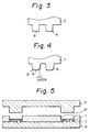
- FIG. 3 and Fig. 4 is a partially sectional view of a mold used for an embodiment of the method of producing a clutch driven plate according to the present invention, each figure showing the shape of the cylindrical projection.
- Fig. 5 and Fig. 6 are partially sectional views of a mold used for an embodiment of the method of producing a clutch driven plate according to the present invention, the figures showing the embodiment of the method according to the present invention being carried out.
- Fig. 7 and Fig. 8 are partially sectional views of a mold used for an embodiment of the method of producing a clutch driven plate according to the present invention, the figures showing the embodiment of the method according to the present invention being carried out.
- Fig. 9 is a front elevation view of an embodiment of the clutch driven plate according to the present invention.
- Fig. 10 is a sectional view on the line II-II of Fig. 9.
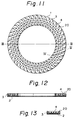
- Fig. 11 is a front elevation view of an embodiment of the clutch driven plate according to the present invention.
- Fig. 12 is a sectional view on the line III-III of Fig. 11.
- Fig. 13 is a partially sectional view on the line IV-IV of Fig. 11.
- Fig. 14 is a partially sectional view of a mold used for production of the clutch driven plate shown in Fig. 11.
- Fig. 1 is a perspective view of an embodiment of the clutch driven plate according to the present invention
- the clutch driven plate shown in Fig. 1 consists of a back-up plate 2 and a clutch facing plate 3 molded from a clutch facing material comprising a fiber, a binder, and a friction modifier and fixed onto the back-up plate 2, and a number of dimples 4 are formed on the surface of the clutch facing plate 3.
- the back-up plate to be used in the present invention has a ring form and is constructed from a metal plate or metal wire of steel, copper, aluminum, aluminum alloys including dulalumin, magnesium, etc., woven fabric, or the like. It is preferable to use a ring made of a light metal having a gravity of not more than 5, for example, aluminum, aluminum alloys including dulalumin, and magnesium. Aluminum alloys are particularly preferably used. Also, considering application of an adhesive, such as phenol adhesives or nitrile adhesives, on the surface of the back-up plate to be fixed with the clutch facing plate, it is preferable to use a back-up plate with a surface roughened by shot blasting, buffing, chemical polishing, or the like.
- the clutch facing plate to be used in the present invention may be produced by molding a clutch facing material comprising a fiber, a binder, and a friction modifier.
- the fiber to be used in the present invention may be any one generally used for friction materials, and some illustrative examples of the fiber to be used in the present invention include asbestos, glass fiber, aramid fiber, carbon fiber, ceramic fiber, metal fiber, rayon (staple) fiber, and polyacrylic fiber.
- the preferred fibers are those of bulked type or short fiber of 10 mm or less in length.
- the binder to be used in the present invention may be any one generally used for friction material, and some illustrative examples of the binder include thermosetting resins, such as melamine resins and phenol resins, and rubber binders, such as NBR and SBK.
- thermosetting resins such as melamine resins and phenol resins
- rubber binders such as NBR and SBK.
- the friction modifier to be used in the present invention may be any one generally used for friction material, and some illustrative examples of the friction modifier include cashew dust, friction dust, graphite, barium sulfate, clay, calcium carbonate, aluminum powder, copper powder, zinc power, lead sulfide, alumina, and antimony trioxide.
- the clutch facing material preferably comprises 30 to 50 parts by weight of the fiber, 20 to 40 parts by weight of the binder, and 10 to 40 parts by weight of the friction modifier.
- the preferred total area of the openings of the dimples is equal to or smaller than the area of the surface of the clutch driven plate exclusive of the openings of the dimples.
- a total area of the openings larger than the above-described range makes the space between dimples narrow and tends to cause cracks in the clutch facing plate between dimples.
- the preferred volume percentage of the total volume of the dimples in the clutch facing plate is not less than 20 % of the volume of a clutch facing plate without dimple. If the total volume of the dimples is less than 20 %, the lightening effect may become insufficient.
- Each dimple is preferably so distributed as to be spaced equally in the circumferential direction on the surface of the clutch facing plate.
- the openings of the dimples may have any form, for example, a triangle, a square, an ellipse, a circle, or a hexagon. Considering the easiness in formation of the dimples, the preferred form is a circle.
- the obtained laminate consisting of a back-up plate and a clutch facing plate is cured and aged by heat-treatment at 150 to 400 °C . Thereafter, the surface of the clutch facing plate is ground to obtain a clutch driven plate having the required thickness, and the obtained clutch driven plate is finished by making rivet holes.
- Formation of dimples may be carried out after the thermo-compression molding by using a drilling machine. However, it is preferable to carry out formation of dimples at the time of thermo-compression molding.
- formation of dimples and thermo-compression molding is carried out simultaneously by putting a back-up plate in a female mold having a flat bottom, putting a clutch facing material comprising a fiber, a binder, and a friction modifier on the back-up plate so as to form two layers consisting of a lower layer of the back-up plate and an upper layer of the clutch facing material layer, and molding the layered back-up plate and clutch facing material into an integral body by thermo-compression molding utilizing a force mold having a number of projections on its surface so as to form a number of dimples on the surface of the molded clutch facing plate.
- the preferred form of the projections is a cylindrical form which makes the opening of dimples circular.
- a cylindrical projection pushes away the clutch facing material almost uniformly and reduces the irregularity of the material.
- dimples each having a dimple diameter of from ⁇ 2 mm to ⁇ 15 mm If the dimple diameter is more than ⁇ 15 mm, the clutch facing material may not efficiently pushed away. If the dimple diameter is less than ⁇ 2 mm, the total area of the side surfaces of the dimples will become too large causing sticking in the mold.
- the stress generated by the difference in heat expansion coefficient between the back-up plate and the clutch facing plate becomes smaller at the regions of the dimples, and the degree of warp is reduced accordingly. Also, because the apparent elastic modulus of the clutch facing plate is as well reduced more than the clutch facing plate having no dimple, the stress is more reduced, and the warp is further decreased.
- the weight of the clutch facing plate according to the present invention is reduced by the weight corresponding to the volume of the dimples, the obtained clutch driven plate is lightened, and therefore, the moment of inertia of the clutch facing plate applied on the back-up plate is reduced resulting in an improved burst strength of the clutch driven plate.
- thermo-compression molding When integral molding of back-up plate and clutch facing plate and formation of dimples are performed simultaneously by the thermo-compression molding using a mold having projections, it is desirable to use a mold which has cylindrical projections each having a rounded top.
- the top of the cylindrical projection is not rounded, a larger amount of clutch facing material tends to remain under a dimple, i.e. between the cylindrical projection and the back-up plate, because of the low flowability of the clutch facing material, and the lightening effect may become insufficient. Additionally, the density of the whole clutch facing plate will become low, and the clutch facing plate may gets fragile resulting in an insufficient strength of the clutch driven plate. Also, the flagility may make the clutch facing plate apt to crack at the time of removal of mold after thermo-compression molding.
- Fig. 3 is a partially sectional view of an example of the force mold having cylindrical projections with rounded tops. It is particularly preferable to use a mold in which each cylindrical projection is tapered and has a rounded top as shown in Fig. 4.
- the clutch facing material can be easily pressed away from the gaps between the back-up plate and the cylindrical projections, and both the decrease in the density of the clutch facing plate after molding and the cracking of the clutch facing plate at the time of removal of the mold can be prevented.
- the density of the clutch facing plate beside the side faces of the cylindrical projections can be further increased as the cylindrical projections are pressed in.
- the shearing force generated between the cylindrical projections and the clutch facing plate on the side faces of the projections will be decreased, and the clutch facing plate can be prevented from cracking.
- the above-described inconvenience can also be dissolved by employing a method wherein the production of the integral body consisting of a clutch facing plate and a back-up plate and the formation of the dimples are carried out by preforming the clutch facing material so as to form a number of dimples on the surface of the clutch facing material layer, which is to be the surface of the clutch facing plate, before or after making two layers with the back-up plate and the clutch facing material and subsequently, thermo-compression molding the two layers consisting of the back-up plate layer and the clutch facing material layer provided with the dimples to mold the two layers into an integral body.
- An embodiment of the method comprises putting a clutch facing material comprising a fiber, a binder, and a friction modifier in a female mold having a number of cylindrical projections, preforming the clutch facing material so as to form a number of dimples on the lower surface of the clutch facing material, putting a back-up plate on the upper surface of the preformed clutch facing material, and thermo-compression forming the back-up plate layer and the preformed clutch facing material layer by clamping a force mold to integrate the two layers.
- a clutch facing material 7 is put in a female mold with cylindrical projections (12, 10, 11) followed by clamping at room temperature and at a pressure of preferably 50 to 1,000 bar, more preferably 200 to 600 bar to form the dimple portions, and subsequently, as shown in Fig. 6, a back-up plate 3 is put on the clutch facing material 7 followed by clamping preferably at a temperature of 80 to 300 °C , and at a pressure of 50 to 1,000 bar.
- a force mold provided with a number of pins slidable upwardly and downwardly through it is used and the production of the integral body consisting of a clutch facing plate and a back-up plate and the formation of the dimples are carried out by putting a back-up plate in a female mold, putting a clutch facing material comprising a fiber, a binder, and a friction modifier on the back-up plate, pressing the pins of the force mold in the clutch facing material to form a number of dimples on the surface of the clutch facing material, and thermo-compression molding the back-up plate and the clutch facing material provided with the dimples to mold them into an integral body by clamping the force mold with the pins remaining pressed in the clutch facing material.
- Fig. 7 and Fig. 8 show an example of the mold suitably used for this production method.
- the mold (13, 14, 15) shown in Fig. 7 is provided with slidable pins 18.
- a back-up plate 2 is put in the female mold 15, and a clutch facing material 7 is then put on the back-up plate 2 evenly.
- pins 18 are pressed in the clutch facing material 7 preferably under a condition of a temperature of 80 to 300 °C and at a pressure of 200 to 1,500 bar, and, as shown in Fig. 8, the whole mold is then clamped preferably under the condition of a temperature of 80 to 300 °C and at a pressure of 50 to 1,000 bar to thermo-compression mold an integral clutch driven plate.
- This method is desirable because it permits a clutch facing material to be put in a mold uniformly in the circumferential direction without being obstructed by cylindrical projections.
- thermo-compression molding of a clutch driven plate by clamping is carried out after the dimples have previously been formed on the surface of the clutch facing material, only a small amount of clutch facing material remains under the dimples, and a light clutch driven plate can be obtained. Further, because in this method, the molded clutch facing plate has a high density, cracking or breakage of the clutch facing plate at the time of removal of molds after thermo-compression molding can be prevented.
- the clutch driven plate of the present invention with air inlet pores, each of the air inlet pores running through the clutch driven plate from the surface of the back-up plate to the bottom of each dimple respectively and having a smaller opening area than the dimples.
- Fig. 9 and Fig. 10 show an embodiment of the clutch driven plate according to the present invention, Fig. 9 being a front view of the clutch driven plate and Fig. 10 being a sectional view on the line I-I of Fig. 9.
- This clutch driven plate 1 is provided with air inlet pores 19, each of the air inlet pores 19 running through the clutch driven plate 1 from the surface of the back-up plate 2 to the bottom of each dimple 4 in the clutch facing plate 3 respectively.
- a negative pressure generates in the dimples at the time the clutch is disengaged during a high speed rotation, and disengagement of clutch may sometimes become uneasy.
- the air inlet pores as shown in Fig. 9 and Fig.
- each air inlet pore is smaller than that of each dimple, and is preferably 0.5 to 3 mm in diameter.
- Production of the air inlet pores may be carried out by using a drilling machine or the like.
- the uneasiness on disengagement due to the negative pressure generated in the dimples can also be prevented by providing the surface of the clutch facing plate with at least one groove having a width smaller than the maximum width of the opening of each dimple, so that at least one of the both ends of the groove reaches the outward peripheral edge or inward peripheral edge of the clutch facing plate and each dimple is crossed through by the groove on the surface of the clutch facing plate.
- Fig. 11, Fig. 12, and Fig. 13 show an embodiment of the clutch driven plate according to the present invention, the clutch driven plate having a number of air inlet grooves.
- Fig. 11 is a front view of the clutch driven plate
- Fig. 12 is a sectional view on the line III-III of Fig. 11,
- Fig. 13 is a partially sectional view on the line IV-IV of Fig. 11.
- a number of air inlet grooves 20 are formed on the surface of the clutch facing plate 3, each air inlet groove 20 reaching the outward and inward peripheral edges of the clutch facing plate 3 and crossing through four dimples 4 on the surface of the clutch facing plate 3 respectively.
- the width of each air inlet groove 20 is smaller than the maximum width of the opening of each dimple 4.
- the air inlet grooves 20 function so as to prevent generation of negative pressure in the dimples 4. That is, each groove reaches the outward and inward peripheral edges of the clutch facing plate 3 so that the dimples can be ventilated with the outside air and therefore, generation of negative pressure can be prevented.
- the clutch driven plate provided with dimples and air inlet grooves is produced by thermo-compression molding
- it is suitable, for performing the thermo-compression molding and the formation of dimples and air inlet grooves simultaneously, to use a mold as shown in Fig. 14 which comprises a mold 22 having cylindrical projections 8 and streak-like projections 23 for forming respectively the air inlet grooves 20 and dimples 4 as shown in Fig. 11.
- a mold as shown in Fig. 14 which comprises a mold 22 having cylindrical projections 8 and streak-like projections 23 for forming respectively the air inlet grooves 20 and dimples 4 as shown in Fig. 11.
- a clutch driven plate having a form as shown in Fig. 1 was produced.
- the clutch driven plate produced in this example had a ring form of 130 mm in internal diameter, 200 mm in external diameter, and 3.5 mm in thickness and consisted of a back-up plate 2 made of an aluminum alloy and a clutch facing plate 3 with a number of dimples 4.
- the clutch driven plate was produced by putting a clutch facing material consisting of a fiber, a binder, and a friction modifier on a back-up plate 2 made of an aluminum alloy, and thermo-compression molding them simultaneously with formation of a number of dimples 4.
- the clutch driven plate is to be used by riveting it to both sides of a cushion spring of a dry clutch (not illustrated) with the surface of the back-up plate 2 facing a disc.
- a back-up plate 2 was produced.
- a back-up plate 2 was punched out into the above-described ring form from an aluminum alloy plate (ALP 5052 H34) of 1mm in thickness by using a punching press.
- the surface of the back-up plate 2 to be fixed to the clutch facing plate 3 was roughened by abrasion treatment and then washed with an alkali degreasing agent.
- a phenol resin adhesive was then put in the mold 6 as shown in Fig. 2 with the applied surface looking upward.
- a clutch facing plate 3 was then formed. 30 parts by weight of a glass short fiber (fiber length: 5 mm) and 10 parts by weight of a bulked aramid fiber as the fiber, 30 parts by weight of a melamine resin and 10 parts by weight of NBR and a vulcanizing agent therefor as the binder, and 15 parts by weight of cashew dust and 5 parts by weight of barium sulfate as the friction modifier were mixed by using a Henschel mixer to prepare a clutch facing material 7.
- thermo-compression molding was carried out by clamping the force mold 5 under the condition of a temperature of 150 °C and a surface pressure of 600 bar.
- the obtained clutch driven plate 1 consisted of a back-up plate 2 of 1 mm in thickness and a clutch facing plate 3 of 2.5 mm in thickness (dimple diameter: ⁇ 7 mm, dimple depth: 2.0 mm, total area of the openings of dimples: 65 cm2 (36 % of the area of the surface of the clutch facing plate including the openings of dimples.)).
- the obtained clutch driven plate warped only slightly, and was so light as 0.916 N.
- the density of the clutch facing plate was 0.0132 N/cm3.
- a clutch driven plate having a form as shown in Fig. 1 was produced.
- the clutch driven plate produced in this example had a ring form of 130 mm in internal diameter, 200 mm in external diameter, and 3.5 mm in thickness and consisted of a back-up plate 2 made of an aluminum alloy and a clutch facing plate 3 with a number of dimples 4.
- the clutch driven plate was produced by putting a clutch facing material consisting of a fiber, a binder, and a friction modifier on a back-up plate 2 made of an aluminum alloy, and thermo-compression molding them simultaneously with formation of a number of dimples 4.
- the clutch driven plate is to be used by riveting it to both sides of a cushion spring of a dry clutch (not illustrated) with the surface of the back-up plate 2 facing cushion springs.
- a back-up plate 2 was produced.
- a back-up plate 2 was punched out into the above-described ring form from an aluminum alloy plate (ALP 5052 H34) of 1mm in thickness by using a punching press.
- the surface of the back-up plate 2 to be fixed to the clutch facing plate 3 was washed with methanol and was then roughened by abrasion treatment.
- a phenol resin adhesive was put in the mold 6 as shown in Fig. 2 with the applied surface looking upward.
- a clutch facing plate 3 was then formed. 30 parts by weight of a glass short fiber (fiber length: 5 mm) and 10 parts by weight of a bulked aramid fiber as the fiber, 30 parts by weight of a melamine resin and 10 parts by weight of NBR and a vulcanizing agent therefor as the binder, and 15 parts by weight of cashew dust and 5 parts by weight of barium sulfate as the friction modifier were mixed by using a Henschel mixer to prepare a clutch facing material 7.
- thermo-compression molding was carried out by clamping the force mold 5, which had a number of cylindrical projections with rounded (R: 1 mm) edges of tops as shown in Fig. 3, under the condition of a temperature of 150 °C and a surface pressure of 200 bar.
- the obtained laminate was then heat treated at 200 °C , to cure and age the clutch facing plate 3.
- the obtained laminate consisted of a back-up plate 2 of 1 mm in thickness and a clutch facing plate 3 of 3.2 mm in thickness (dimple diameter: ⁇ 7 mm, dimple depth: 3.0 mm).
- the obtained clutch driven plate 1 consisted of a back-up plate 2 of 1 mm in thickness and a clutch facing plate 3 of 2.5 mm in thickness (dimple diameter: ⁇ 7 mm, dimple depth: 2.3 mm, total area of the openings of dimples: 65 cm2 (36 % of the area of the surface of the clutch facing plate including the openings of dimples.)).
- the clutch facing material flowed out smoothly from the spaces between the cylindrical projections 8 and the back-up plate 2, and the obtained clutch driven plate had a clutch facing plate having a high density ( 0.0140 N/cm3).
- the total weight of the obtained clutch driven plate was 0.946 N.
- a clutch driven plate was produced in the same manner as in Example 2 with the exception that the force mold 5 was replaced with a force mold which had a number of cylindrical projections not only rounded but also tapered as shown in Fig. 4. Such a mold was easily removed, and the obtained clutch driven plate had a high density (0.0140 N/cm3), and was free from cracks or breakage.
- a clutch driven plate having a form as shown in Fig. 1 was produced.
- the clutch driven plate produced in this example had a ring form of 130 mm in internal diameter, 200 mm in external diameter, and 3.5 mm in thickness and consisted of a back-up plate 2 made of an aluminum alloy and a clutch facing plate 3 with a number of dimples 4.
- the clutch driven plate was produced by putting a clutch facing material consisting of a fiber, a binder, and a friction modifier on a back-up plate 2 made of an aluminum alloy, and thermo-compression molding them into one body.
- the clutch driven plate is to be used by riveting it to both sides of a cushion spring of a dry clutch (not illustrated) with the surface of the back-up plate 2 facing a disc.
- a back-up plate 2 was produced.
- a back-up plate 2 was punched out into the above-described ring form from an aluminum alloy plate (ALP 5052 H34) of 1mm in thickness by using a punching press.
- the surface of the back-up plate 2 to be fixed to the clutch facing plate 3 was washed with methanol and was then roughened by abrasion treatment. Subsequently, to the surface applied was a phenol resin adhesive.
- a clutch facing plate 3 was then formed. 30 parts by weight of a glass short fiber (fiber length: 5 mm) and 10 parts by weight of a bulked aramid fiber as the fiber, 30 parts by weight of a melamine resin and 10 parts by weight of NBR and a vulcanizing agent therefor as the binder, and 15 parts by weight of cashew dust and 5 parts by weight of barium sulfate as the friction modifier were mixed by using a Henschel mixer to prepare a clutch facing material 7.
- the obtained laminate consisted of a back-up plate 2 of 1 mm in thickness and a clutch facing plate 3 of 3.2 mm in thickness (dimple diameter: ⁇ 7 mm, dimple depth: 3.0 mm).
- the obtained clutch driven plate 1 consisted of a back-up plate 2 of 1 mm in thickness and a clutch facing plate 3 of 2.5 mm in thickness (dimple diameter: ⁇ 7 mm, dimple depth: 2.3 mm, total area of the openings of dimples: 65 cm2 (36 % of the area of the surface of the clutch facing plate including the openings of dimples.)).
- a clutch driven plate having a form as shown in Fig. 1 was produced by using the same back-up plate and clutch facing material as used in Example 4 and using a mold as shown in Fig. 7 and Fig. 8 which had been provided with a number of pins 18 ( ⁇ 7 mm) slidable upwardly and downwardly.
- the back-up plate 2 was put in a female mold 15, and 0.58N of the clutch facing material 7 was placed on the back-up plate 2 to form a ring with a uniform thickness.
- the slidable pins of the mold were pressed in the clutch facing material at 150 °C and at a surface pressure of the top surface of the pins of 1,200 bar, and were kept as they were for 15 seconds, to form dimples.
- the pressing bed plates 16 and 17 were then placed into position as shown in Fig. 8, and the mold was then clamped at 150 °C and at a surface pressure of 600 bar to perform thermo-compression molding.
- the obtained laminate was cured and aged by heat-treating it at 200 °C .
- the obtained laminate consisted of a back-up plate 2 of 1 mm in thickness and a clutch facing plate 3 of 3.2 mm in thickness (dimple diameter: ⁇ 7 mm, dimple depth: 3.0 mm).
- the obtained clutch driven plate 1 consisted of a back-up plate 2 of 1 mm in thickness and a clutch facing plate 3 of 2.5 mm in thickness (dimple diameter: ⁇ 7 mm, dimple depth: 2.3 mm, total area of the openings of dimples: 65 cm2 (36 % of the area of the surface of the clutch facing plate including the openings of dimples.)).
- the scattering of the density of the clutch facing plate in the circumferential direction was reduced because the clutch facing material could be uniformly put in the mold, and the clutch facing plate had a high density (0.0140 N/cm3).
- the total weight of the clutch driven plate was 0.914 N.
- FIG. 9 is a front view of the clutch driven plate produced in this Example
- Fig. 10 is a sectional view on the line I-I of Fig. 9.
- the clutch driven plate produced in this Example had a ring form of 130 mm in internal diameter, 200 mm in external diameter, and 3.5 mm in thickness, consisted of a back-up plate 2 made of an aluminum alloy and a clutch facing plate 3 with a number of dimples 4, and was provided with air inlet pores each of which runs through from the surface of the back-up plate 2 to the bottom of each dimple.
- the clutch driven plate was produced by putting a clutch facing material consisting of a fiber, a binder, and a friction modifier on a back-up plate 2 made of an aluminum alloy, thermo-compression molding them simultaneously with formation of a number of dimples 4, and making the air inlet pores each of which runs through from the surface of the back-up plate to the bottom of each dimple.
- the clutch driven plate is to be used by riveting it to both side of a cushion spring of a dry clutch (not illustrated) with the surface of the back-up plate 2 facing a disc.
- a back-up plate 2 was produced.
- a back-up plate 2 was punched out into the above-described ring form from an aluminum alloy plate (ALP 5052 H34) of 1mm in thickness by using a punching press.
- a surface of the back-up plate 2 to be fixed to the clutch facing plate 3 was roughened by abrasion treatment and then washed with an alkali degreasing agent.
- a phenol resin adhesive was put in the female mold 6 as shown in Fig. 2 with the applied surface looking upward.
- a clutch facing plate 3 was then formed. 30 parts by weight of a glass short fiber (fiber length: 5 mm) and 10 parts by weight of a bulked aramid fiber as the fiber, 30 parts by weight of a melamine resin and 10 parts by weight of NBR and a vulcanizing agent therefor as the binder, and 15 parts by weight of cashew dust and 5 parts by weight of barium sulfate as the friction modifier were mixed by using a Henschel mixer to prepare a clutch facing material 7.
- the obtained laminate was then heat treated at 200 °C to cure and age the clutch facing plate 3.
- the obtained laminate consisted of a back-up plate 2 of 1 mm in thickness and a clutch facing plate 3 of 3.5 mm in thickness (dimple diameter: ⁇ 7 mm, dimple depth: 3.0 mm).
- a piercing hole of ⁇ 1 mm was made at the center of every dimple by using a drilling machine to provide the air inlet holes 19.
- the obtained clutch driven plate 1 consisted of a back-up plate 2 of 1 mm in thickness and a clutch facing plate 3 of 2.5 mm in thickness (dimple diameter: ⁇ 7 mm, dimple depth: 2.0 mm, total area of the openings of dimples: 65 cm2 (36 % of the area of the surface of the clutch facing plate including the openings, diameter of the air inlet pore: ⁇ 1 mm.)).
- the obtained clutch driven plate warped only slightly, and there occurred no worsening of disengagement in the clutch fixed with the clutch driven plate.
- the clutch facing plate had a density of 0.0132 N/cm3 , and the total weight of the clutch driven plate was 0.882 N.
- FIG. 11 is a front view of the clutch driven plate produced in this Example
- Fig. 12 is a sectional view on the line II-II of Fig. 11, and
- Fig. 13 is a partially sectional view on the line III-III of Fig. 11.
- the clutch driven plate produced in this Example had a ring form of 130 mm in internal diameter, 200 mm in external diameter, and 3.5 mm in thickness, consisted of a back-up plate 2 made of an aluminum alloy and a clutch facing plate 3 with a number of dimples 4, and was provided with air inlet grooves, 20 each of which reached the outward and inward peripheral edges of the clutch facing plate and crossed through four dimples.
- the clutch driven plate was produced by putting a clutch facing material consisting of a fiber, a binder, and a friction modifier on a back-up plate 2 made of an aluminum alloy, and thermo-compression molding them simultaneously with formation of a number of dimples 4 and air inlet grooves 20.
- the clutch driven plate is to be used by riveting it to both sides of a cushion spring of a dry clutch (not illustrated) with the surface of the back-up plate 2 facing a disc.
- a back-up plate 2 was produced.
- a back-up plate 2 was punched out into the above-described ring form from an aluminum alloy plate (ALP 5052 H34) of 1mm in thickness by using a punching press.
- the surface of the back-up plate 2 to be fixed to the clutch facing plate 3 was roughened by abrasion treatment and then washed with an alkali degreasing agent.
- a phenol resin adhesive was put in the female mold 21 as shown in Fig. 14 with the applied surface looking upward.
- a clutch facing plate 3 was then formed. 30 parts by weight of a glass short fiber (fiber length: 5 mm) and 10 parts by weight of a bulked aramid fiber as the fiber, 30 parts by weight of a melamine resin and 10 parts by weight of NBR and a vulcanizing agent therefor as the binder, and 15 parts by weight of cashew dust and 5 parts by weight of barium sulfate as the friction modifier were mixed by using a Henschel mixer to prepare a clutch facing material 7.
- the obtained laminate consisted of a back-up plate 2 of 1 mm in thickness and a clutch facing plate 3 of 3.5 mm in thickness (dimple's diameter: ⁇ 7 mm, dimple's depth: 3.0 mm, width of air inlet groove: 1 mm, depth of the air inlet groove: 2.7 mm).
- the obtained clutch driven plate 1 consisted of a back-up plate 2 of 1 mm in thickness and a clutch facing plate 3 of 2.5 mm in thickness (dimple diameter: ⁇ 7 mm, dimple depth: 2.0 mm, total area of the openings of dimples: 65 cm2 (36 % of the area of the surface of the clutch facing plate including the openings of dimples, width of air inlet groove: 1 mm, depth of air inlet groove: 1.7 mm)).
- the obtained clutch driven plate warped only slightly, and there occurred no worsening of disengagement in the clutch fixed with the clutch driven plate.
- the clutch facing plate had a density of 0.0132 N/cm3, and the total weight of the clutch driven plate was 0.907 N.
- a clutch facing plate having a form as shown in Fig. 1 was produced in the same manner as in Example 1.
- the obtained clutch driven plate 1 consisted of a back-up plate of 1 mm in thickness and a clutch facing plate of 2.5 mm in thickness (dimple's diameter: ⁇ 7.6 mm, dimple's depth: 2.5 mm, total area of the openings of dimples: 72.6 cm2 (40 % of the area of the surface of the clutch facing plate including the openings).
- the obtained clutch driven plate warped only slightly.
- the clutch facing plate had a density of 0.014 N/cm3, and the total weight of the clutch driven plate was 0.900 N.
Landscapes
- Engineering & Computer Science (AREA)
- Mechanical Engineering (AREA)
- General Engineering & Computer Science (AREA)
- Chemical & Material Sciences (AREA)
- Composite Materials (AREA)
- Mechanical Operated Clutches (AREA)
- Braking Arrangements (AREA)
Claims (7)
- Kupplungsscheibe, die eine Kupplungsbelagscheibe (3) mit eingesenkten Abschnitten, welche aus einem eine Faser, ein Bindemittel und einen Reibungsmodifikator enthaltenden Kupplungsbelagmaterial besteht, und eine die Kupplungsbelagscheibe (3) tragende Halteplatte (2) umfaßt, dadurch gekennzeichnet, daß eine Anzahl von Vertiefungen (4) in der Oberfläche der Kupplungsbelagscheibe (3) gebildet sind und die Gesamtfläche der Öffnungen in den Vertiefungen (4) gleich oder kleiner der Fläche des nicht eingesenkten Abschnittes in der Oberfläche der Kupplungsbelagscheibe (3) ist, daß der Volumenanteil des Gesamtvolumens der Vertiefungen (4) in der Kupplungsbelagscheibe (3) nicht geringer als 20% des Volumens der Kupplungsbelagscheibe (3) ohne die Vertiefungen ist, und daß die Vertiefungen (4) derartig verteilt sind, daß sie auf der Oberfläche der Kupplungsbelagscheibe (3) gleichmäßig in Umfangsrichtung beabstandet sind.
- Kupplungsscheibe nach Anspruch 1, wobei eine Anzahl von Lufteinlaßporen in der Kupplungsbelagscheibe vorgesehen sind, wobei jede der Lufteinlaßporen jeweils durch die Kupplungsbelagscheibe von der Oberfläche der Halteplatte (2) bis zum Boden jeder Vertiefung (4) führt und eine geringere Querschnittsfläche als die Vertiefungen (4) aufweist.
- Kupplungsscheibe nach Anspruch 1, wobei zumindest eine Nut (20), die eine geringere Breite als die Maximalbreite der Öffnung jeder Vertiefung (4) aufweist, in der Oberfläche der Kupplungsbelagscheibe (3) gebildet ist, derart daß
zumindest eines der beiden Enden der Nut (20) die äußere oder die innere Umfangskante der Kupplungsbelagscheibe erreicht, und
jede Vertiefung (4) von der Nut in der Oberfläche der Kupplungsbelagscheibe (3) gekreuzt wird. - Kupplungsscheibe nach einem der Ansprüche 1 bis 3, wobei jede in der Oberfläche der Kupplungsbelagscheibe gebildete Vertiefung (4) eine kreisförmige Öffnung mit einem Durchmesser von 2 mm bis 15 mm aufweist.
- Verfahren zur Herstellung einer Kupplungscheibe, mit den Schritten:
Einsetzen einer Halteplatte in eine Matrize, die ein Gegenstück zu einer Stempelform bildet, welche mit einer Anzahl auf- und abwärts durch die Stempelform verschiebbarer Stifte versehen ist;
Aufbringen eines Kupplungsbelagmaterials, bestehend aus einer Faser, einem Bindemittel und einem Reibungsmodifikator, auf die Halteplatte;
Drücken der verschiebbaren Stifte der Stempelform abwärts in das Kupplungsbelagmaterial zur Bildung einer Anzahl von Vertiefungen in der Oberfläche des Kupplungsbelagmaterial; und
Pressen der Stempelform unter Belassung der verschiebbaren Stifte im Kupplungsbelagmaterial, um die Halteplatte und das mit den Vertiefungen versehene Kupplungsbelagmaterial wärmeformzupressen zur Bildung eines integralen Körpers, der aus der Halteplatte und einer Kupplungsbelagscheibe besteht und der eine mit einer Anzahl von Vertiefungen versehene Oberfläche aufweist. - Verfahren nach Anspruch 5, wobei jeder der in der Stempelform vorgesehenen Stifte zylindrisch ist und ein gerundetes unteres Ende aufweist.
- Verfahren nach Anspruch 5, wobei jeder der in der Stempelform vorgesehenen Stifte zylindrisch ist und ein konisches unteres Ende aufweist.
Applications Claiming Priority (10)
| Application Number | Priority Date | Filing Date | Title |
|---|---|---|---|
| JP295738/88 | 1988-11-22 | ||
| JP63295738A JPH07109226B2 (ja) | 1988-11-22 | 1988-11-22 | クラッチ被動板及びその製造法 |
| JP12076/89 | 1989-01-20 | ||
| JP12075/89 | 1989-01-20 | ||
| JP1012076A JPH02253021A (ja) | 1989-01-20 | 1989-01-20 | クラッチ被動板の製造法 |
| JP1012075A JPH02195036A (ja) | 1989-01-20 | 1989-01-20 | クラッチ被動板の製造法 |
| JP1193392A JPH0361730A (ja) | 1989-07-26 | 1989-07-26 | クラッチ被動板 |
| JP193392/89 | 1989-07-26 | ||
| JP1193393A JPH0361731A (ja) | 1989-07-26 | 1989-07-26 | クラッチ被動板 |
| JP193393/89 | 1989-07-26 |
Publications (2)
| Publication Number | Publication Date |
|---|---|
| EP0370476A1 EP0370476A1 (de) | 1990-05-30 |
| EP0370476B1 true EP0370476B1 (de) | 1994-02-02 |
Family
ID=27519362
Family Applications (1)
| Application Number | Title | Priority Date | Filing Date |
|---|---|---|---|
| EP89121540A Expired - Lifetime EP0370476B1 (de) | 1988-11-22 | 1989-11-21 | Kupplungsscheiben und Verfahren zu ihrer Herstellung |
Country Status (5)
| Country | Link |
|---|---|
| US (2) | US5004089A (de) |
| EP (1) | EP0370476B1 (de) |
| KR (1) | KR920009820B1 (de) |
| CA (1) | CA2002057C (de) |
| DE (1) | DE68912899T2 (de) |
Cited By (1)
| Publication number | Priority date | Publication date | Assignee | Title |
|---|---|---|---|---|
| AT410015B (de) * | 1997-07-04 | 2003-01-27 | Hoerbiger & Co | Reibring für kupplungen oder bremsen und verfahren zur herstellung eines reibringes |
Families Citing this family (46)
| Publication number | Priority date | Publication date | Assignee | Title |
|---|---|---|---|---|
| US5525642A (en) * | 1991-05-30 | 1996-06-11 | The Dow Chemical Company | Electroresponsive polymer systems |
| USRE37548E1 (en) | 1991-08-12 | 2002-02-19 | Bill J. Hays | Clutch design and manufacture |
| US5184704A (en) * | 1991-08-12 | 1993-02-09 | Hays Bill J | Clutch design and manufacture |
| TW224065B (de) * | 1992-07-01 | 1994-05-21 | Sumitom Chemicals Co Ltd | |
| JP2851225B2 (ja) * | 1993-06-30 | 1999-01-27 | 大同メタル工業株式会社 | 摩擦用部材 |
| DE4431642B4 (de) * | 1993-09-16 | 2007-05-16 | Luk Lamellen & Kupplungsbau | Reibbelag |
| FR2729726B1 (fr) * | 1995-01-23 | 1997-04-18 | Antonov Automotive Europ | Embrayage multi-disques, transmission automatique ainsi equipee et procede de realisation |
| DE19626688B4 (de) * | 1995-07-14 | 2012-04-12 | Schaeffler Technologies Gmbh & Co. Kg | Reibbelag für eine Kupplungsscheibe sowie damit ausgerüstete Kupplungsscheibe |
| JPH09126257A (ja) * | 1995-10-27 | 1997-05-13 | Shinko Electric Co Ltd | 摩擦式継手の摩擦板 |
| AT405494B (de) * | 1996-02-14 | 1999-08-25 | Miba Frictec Gmbh | Verfahren zum herstellen einer ebenen reiblamelle |
| EP0892896B1 (de) * | 1996-04-08 | 2004-07-21 | Minnesota Mining And Manufacturing Company | Gemustertes reibungsmaterial, kupplungsscheibenelement und verfahren zur herstellung und benutzen desselben |
| US6524681B1 (en) | 1997-04-08 | 2003-02-25 | 3M Innovative Properties Company | Patterned surface friction materials, clutch plate members and methods of making and using same |
| JPH10331889A (ja) * | 1997-05-29 | 1998-12-15 | Dainatsukusu:Kk | 表面に細孔を施した湿式摩擦板 |
| US6311815B1 (en) | 2000-02-09 | 2001-11-06 | Steel Parts Corporation | Textured separator plate and method of making |
| JP2003042204A (ja) * | 2001-07-31 | 2003-02-13 | Exedy Corp | 2層構造フェーシングの製造方法 |
| DE10157995B4 (de) * | 2001-11-25 | 2006-11-02 | Dr.Ing.H.C. F. Porsche Ag | Verfahren zum Herstellen einer Bremsscheibe mit Perforationen aus faserverstärktem Werkstoff |
| JP3940341B2 (ja) * | 2001-12-20 | 2007-07-04 | 株式会社エクセディ | 2層構造フェーシングの製造方法 |
| US6644453B2 (en) | 2002-02-11 | 2003-11-11 | Borgwarner Inc. | Waved friction plate and assembly |
| JP4260409B2 (ja) * | 2002-03-06 | 2009-04-30 | Nskワーナー株式会社 | ロックアップクラッチ用コアプレートへの摩擦材の接着方法及び接着装置 |
| US20050167871A1 (en) * | 2004-01-29 | 2005-08-04 | Sunil Kesavan | Gas-permeable molds for composite material fabrication and molding method |
| US20060231369A1 (en) * | 2005-04-15 | 2006-10-19 | Eaton Corporation | Clutch disc assembly with direct bond ceramic friction material |
| JP4766925B2 (ja) * | 2005-06-02 | 2011-09-07 | 日清紡ホールディングス株式会社 | 摩擦材の製造方法 |
| JP2007056959A (ja) * | 2005-08-23 | 2007-03-08 | Nisshinbo Ind Inc | 摩擦部材の製造方法 |
| JP4880947B2 (ja) | 2005-08-30 | 2012-02-22 | 株式会社ジェイテクト | 駆動力伝達装置 |
| JP2007071320A (ja) * | 2005-09-08 | 2007-03-22 | Nisshinbo Ind Inc | 摩擦部材の製造方法 |
| US7874624B2 (en) * | 2006-03-31 | 2011-01-25 | Ts Tech Co., Ltd. | Cushion body, seat, and method of manufacturing the same |
| US8418829B2 (en) | 2006-04-03 | 2013-04-16 | Eaton Corporation | Cushioned ceramic driven disc assembly with ceramic friction pads fixed to slotted backer plates |
| US7815030B2 (en) | 2006-04-03 | 2010-10-19 | Eaton Corporation | Key hole slots for cushioned ceramic driven disc assembly incorporating direct bond cushioned ceramic facings |
| DE102006049997A1 (de) * | 2006-10-24 | 2008-04-30 | Zf Friedrichshafen Ag | Verfahren zur Bearbeitung von Reiblamellen und Vorrichtung zur Durchführung des Verfahrens |
| DE102006057112B4 (de) * | 2006-12-05 | 2018-08-30 | Borg Warner Inc. | Reibteil für eine reibschlüssig arbeitende Einrichtung und reibschlüssig arbeitende Einrichtung mit einem solchen Reibteil |
| US9212703B2 (en) * | 2007-08-02 | 2015-12-15 | Gm Global Technology Operations, Llc | Torque-transmitting device having a dimpled friction plate |
| DE102008006817A1 (de) | 2008-01-31 | 2009-08-06 | Tmd Friction Services Gmbh | Vorrichtung zur Herstellung von Reibbelägen |
| AT510786A1 (de) | 2010-11-26 | 2012-06-15 | Miba Frictec Gmbh | Verfahren zur herstellung eines reibelementes |
| US9067342B2 (en) * | 2012-09-26 | 2015-06-30 | Intel Corporation | Mold chase for integrated circuit package assembly and associated techniques and configurations |
| JP6473085B2 (ja) * | 2013-09-09 | 2019-02-20 | 株式会社エクセディ | クラッチ用摩擦材 |
| US10337598B2 (en) | 2014-06-18 | 2019-07-02 | Arb Corporation Limited | Limited slip differential |
| US9914275B1 (en) * | 2014-11-20 | 2018-03-13 | Akebono Brake Industry Co., Ltd. | Thermally-conductive hot press assembly |
| DE102016201508A1 (de) * | 2016-02-02 | 2017-08-03 | Schaeffler Technologies AG & Co. KG | Reibteil |
| DE102016107362B4 (de) * | 2016-04-20 | 2020-01-23 | Federal-Mogul Bremsbelag Gmbh | Pressen mindestens einer Pressmasse mittels mehrerer Pressstempel |
| JP6867783B2 (ja) * | 2016-11-02 | 2021-05-12 | 曙ブレーキ工業株式会社 | 摩擦材組成物及び摩擦材 |
| WO2018143027A1 (ja) * | 2017-02-03 | 2018-08-09 | 住友ベークライト株式会社 | ディスクブレーキ用のブレーキパッドおよびその製造方法 |
| US10850352B2 (en) | 2017-12-21 | 2020-12-01 | GM Global Technology Operations LLC | Method of laser cutting grooves in a friction clutch plate |
| JP6673602B2 (ja) * | 2018-05-31 | 2020-03-25 | 株式会社エフ・シー・シー | 湿式摩擦プレートおよび同湿式摩擦プレートを備えた湿式多板クラッチ装置 |
| FR3083156B1 (fr) * | 2018-06-29 | 2021-11-19 | Valeo Materiaux De Friction | Moule de compression pour fabriquer une garniture de frottement |
| JP6685070B1 (ja) * | 2019-10-25 | 2020-04-22 | 株式会社エフ・シー・シー | 接合部品、同接合部品を備えた多板クラッチ装置および接合部品の製造方法 |
| WO2022174862A1 (de) * | 2021-02-22 | 2022-08-25 | Schaeffler Technologies AG & Co. KG | Rutschkupplungsbelag und trockenlaufende rutschkupplung |
Family Cites Families (29)
| Publication number | Priority date | Publication date | Assignee | Title |
|---|---|---|---|---|
| BE395240A (de) * | ||||
| US1626403A (en) * | 1923-08-15 | 1927-04-26 | Thomas L Gatke | Friction lining and method of forming same |
| US1557670A (en) * | 1924-11-10 | 1925-10-20 | France Murrell R De | Method of making brake shoes |
| US1746110A (en) * | 1929-02-21 | 1930-02-04 | Asbestos Mfg Company | Brake lining |
| US1833414A (en) * | 1930-03-19 | 1931-11-24 | Gen Motors Corp | Clutch friction facing |
| FR966920A (fr) * | 1947-06-02 | 1950-10-20 | Freix Ets | Perfectionnements apportés aux garnitures de friction |
| US2559747A (en) * | 1948-06-04 | 1951-07-10 | Raybestos Manhattan Inc | Production of cone clutch members |
| US2724671A (en) * | 1952-12-30 | 1955-11-22 | Johns Manville | Friction element and method of making the same |
| US2927673A (en) * | 1956-04-19 | 1960-03-08 | Gen Motors Corp | Energy transmitting device |
| US3130172A (en) * | 1958-12-01 | 1964-04-21 | Harvel Res Corp | Compositions of matter and method and steps of making and using the same |
| US3073424A (en) * | 1959-06-15 | 1963-01-15 | Eaton Mfg Co | Friction device |
| DE1575906B1 (de) * | 1966-05-13 | 1970-11-26 | Friedrich Heck | Verfahren zum Herstellen von Sinterreiblamellen |
| US3534842A (en) * | 1968-12-09 | 1970-10-20 | Gen Motors Corp | Lubricated friction device |
| US3998573A (en) * | 1972-01-17 | 1976-12-21 | Abex Corporation | Manufacture of friction elements |
| US3841949A (en) * | 1972-10-25 | 1974-10-15 | Twin Disc Inc | Composite friction plate |
| US4262788A (en) * | 1977-10-14 | 1981-04-21 | Yasunobu Yamamoto | Friction member of non-asbestos |
| US4197352A (en) * | 1977-12-22 | 1980-04-08 | Hooker Chemicals & Plastics Corp. | Composite friction assemblies and methods of making such assemblies |
| DE7827426U1 (de) * | 1978-09-15 | 1979-02-01 | Fichtel & Sachs Ag, 8720 Schweinfurt | Reibbelag |
| JPS5663123A (en) * | 1979-10-26 | 1981-05-29 | Aisin Chem Co Ltd | Clutch facing for wheel |
| US4260047A (en) * | 1979-12-03 | 1981-04-07 | General Motors Corporation | Friction disc and method of making same |
| FR2489455B1 (fr) * | 1980-09-04 | 1986-04-11 | Valeo | Garniture de friction, notamment pour freins, embrayages et autres applications |
| JPS6141022A (ja) * | 1984-08-02 | 1986-02-27 | Toyota Motor Corp | レジンモ−ルドクラツチフエ−シング |
| JPS6170225A (ja) * | 1984-09-12 | 1986-04-11 | Toyota Motor Corp | レジンモ−ルドクラツチフエ−シング |
| JPS61256031A (ja) * | 1985-05-07 | 1986-11-13 | Aisin Chem Co Ltd | クラツチの被動板 |
| US4617165A (en) * | 1985-05-13 | 1986-10-14 | Tsang Peter H S | Molded brake pad |
| US4667534A (en) * | 1985-10-18 | 1987-05-26 | Tochigi-Fuji Sangyo Kabushiki Kaisha | Limited slip differential gear mechanism |
| JPS62110029A (ja) * | 1985-11-07 | 1987-05-21 | Toyota Motor Corp | クラツチフエ−シング |
| AT387395B (de) * | 1987-02-25 | 1989-01-10 | Miba Sintermetall Ag | Verfahren zum beschichten eines stuetztraegers mit einem kunstharzgebundenen reibbelag |
| AT398726B (de) * | 1987-09-29 | 1995-01-25 | Leinweber Anstalt Ing Joh | Verfahren und presse zur herstellung von blöcken |
-
1989
- 1989-11-02 CA CA002002057A patent/CA2002057C/en not_active Expired - Fee Related
- 1989-11-02 US US07/430,248 patent/US5004089A/en not_active Expired - Lifetime
- 1989-11-21 KR KR1019890016932A patent/KR920009820B1/ko not_active Expired
- 1989-11-21 EP EP89121540A patent/EP0370476B1/de not_active Expired - Lifetime
- 1989-11-21 DE DE68912899T patent/DE68912899T2/de not_active Expired - Fee Related
-
1991
- 1991-01-16 US US07/641,858 patent/US5093057A/en not_active Expired - Lifetime
Cited By (1)
| Publication number | Priority date | Publication date | Assignee | Title |
|---|---|---|---|---|
| AT410015B (de) * | 1997-07-04 | 2003-01-27 | Hoerbiger & Co | Reibring für kupplungen oder bremsen und verfahren zur herstellung eines reibringes |
Also Published As
| Publication number | Publication date |
|---|---|
| KR900008197A (ko) | 1990-06-02 |
| CA2002057A1 (en) | 1990-05-22 |
| EP0370476A1 (de) | 1990-05-30 |
| DE68912899D1 (de) | 1994-03-17 |
| DE68912899T2 (de) | 1994-05-19 |
| CA2002057C (en) | 1994-01-25 |
| KR920009820B1 (ko) | 1992-10-22 |
| US5093057A (en) | 1992-03-03 |
| US5004089A (en) | 1991-04-02 |
Similar Documents
| Publication | Publication Date | Title |
|---|---|---|
| EP0370476B1 (de) | Kupplungsscheiben und Verfahren zu ihrer Herstellung | |
| EP0687829B1 (de) | Verstärktes Reibungsmaterial | |
| US7919165B2 (en) | Wet-type friction material and its manufacturing method | |
| GB2216066A (en) | Method of manufacturing a pad for a disk brake | |
| US4652415A (en) | Method of manufacture of a molded friction pad | |
| JPH0989016A (ja) | ディスクブレーキパッド | |
| US5810644A (en) | Method of shaping a friction facing for friction plate assemblies | |
| JPH03255235A (ja) | クラッチ被動板 | |
| JPH0361731A (ja) | クラッチ被動板 | |
| JPH03255234A (ja) | クラッチ被動板及びその製造法 | |
| JPH02142934A (ja) | クラッチ被動板及びその製造法 | |
| JPH02195036A (ja) | クラッチ被動板の製造法 | |
| JPH0361730A (ja) | クラッチ被動板 | |
| JPH11322960A (ja) | 摩擦材 | |
| JPH03272324A (ja) | クラッチ被動板およびその製造法 | |
| JP6584800B2 (ja) | ディスクブレーキパッドの製造方法 | |
| JPH0361729A (ja) | クラッチ被動板及びその製造法 | |
| JPH11303913A (ja) | 摩擦部材用金型、摩擦材仮成形品用金型、摩擦部材の製造方法及び摩擦材仮成形品の製造方法 | |
| JPH04131522A (ja) | クラツチ被動板の製造法 | |
| JPS6170225A (ja) | レジンモ−ルドクラツチフエ−シング | |
| JPH0715298B2 (ja) | クラッチ被動板の製造法 | |
| JPH02253021A (ja) | クラッチ被動板の製造法 | |
| JPS61188425A (ja) | 摩擦材の製造方法 | |
| JPH0211938A (ja) | クラッチ被動板の製造法 | |
| JP2003145568A (ja) | 摩擦材熱成形過程のガス抜き方法 |
Legal Events
| Date | Code | Title | Description |
|---|---|---|---|
| PUAI | Public reference made under article 153(3) epc to a published international application that has entered the european phase |
Free format text: ORIGINAL CODE: 0009012 |
|
| 17P | Request for examination filed |
Effective date: 19891221 |
|
| AK | Designated contracting states |
Kind code of ref document: A1 Designated state(s): DE FR GB IT |
|
| 17Q | First examination report despatched |
Effective date: 19911206 |
|
| GRAA | (expected) grant |
Free format text: ORIGINAL CODE: 0009210 |
|
| ITF | It: translation for a ep patent filed | ||
| AK | Designated contracting states |
Kind code of ref document: B1 Designated state(s): DE FR GB IT |
|
| REF | Corresponds to: |
Ref document number: 68912899 Country of ref document: DE Date of ref document: 19940317 |
|
| ET | Fr: translation filed | ||
| PLBE | No opposition filed within time limit |
Free format text: ORIGINAL CODE: 0009261 |
|
| STAA | Information on the status of an ep patent application or granted ep patent |
Free format text: STATUS: NO OPPOSITION FILED WITHIN TIME LIMIT |
|
| 26N | No opposition filed | ||
| REG | Reference to a national code |
Ref country code: GB Ref legal event code: IF02 |
|
| PGFP | Annual fee paid to national office [announced via postgrant information from national office to epo] |
Ref country code: FR Payment date: 20061108 Year of fee payment: 18 |
|
| PGFP | Annual fee paid to national office [announced via postgrant information from national office to epo] |
Ref country code: GB Payment date: 20061115 Year of fee payment: 18 |
|
| PGFP | Annual fee paid to national office [announced via postgrant information from national office to epo] |
Ref country code: DE Payment date: 20061116 Year of fee payment: 18 |
|
| PGFP | Annual fee paid to national office [announced via postgrant information from national office to epo] |
Ref country code: IT Payment date: 20061130 Year of fee payment: 18 |
|
| GBPC | Gb: european patent ceased through non-payment of renewal fee |
Effective date: 20071121 |
|
| PG25 | Lapsed in a contracting state [announced via postgrant information from national office to epo] |
Ref country code: DE Free format text: LAPSE BECAUSE OF NON-PAYMENT OF DUE FEES Effective date: 20080603 |
|
| REG | Reference to a national code |
Ref country code: FR Ref legal event code: ST Effective date: 20080930 |
|
| PG25 | Lapsed in a contracting state [announced via postgrant information from national office to epo] |
Ref country code: GB Free format text: LAPSE BECAUSE OF NON-PAYMENT OF DUE FEES Effective date: 20071121 |
|
| PG25 | Lapsed in a contracting state [announced via postgrant information from national office to epo] |
Ref country code: FR Free format text: LAPSE BECAUSE OF NON-PAYMENT OF DUE FEES Effective date: 20071130 |
|
| PG25 | Lapsed in a contracting state [announced via postgrant information from national office to epo] |
Ref country code: IT Free format text: LAPSE BECAUSE OF NON-PAYMENT OF DUE FEES Effective date: 20071121 |