EP0370234A2 - Gorge de remplissage de radiateur avec bouchon - Google Patents
Gorge de remplissage de radiateur avec bouchon Download PDFInfo
- Publication number
- EP0370234A2 EP0370234A2 EP89119492A EP89119492A EP0370234A2 EP 0370234 A2 EP0370234 A2 EP 0370234A2 EP 89119492 A EP89119492 A EP 89119492A EP 89119492 A EP89119492 A EP 89119492A EP 0370234 A2 EP0370234 A2 EP 0370234A2
- Authority
- EP
- European Patent Office
- Prior art keywords
- counter
- radiator
- curve
- bayonet
- stroke
- Prior art date
- Legal status (The legal status is an assumption and is not a legal conclusion. Google has not performed a legal analysis and makes no representation as to the accuracy of the status listed.)
- Granted
Links
Images


Classifications
-
- F—MECHANICAL ENGINEERING; LIGHTING; HEATING; WEAPONS; BLASTING
- F01—MACHINES OR ENGINES IN GENERAL; ENGINE PLANTS IN GENERAL; STEAM ENGINES
- F01P—COOLING OF MACHINES OR ENGINES IN GENERAL; COOLING OF INTERNAL-COMBUSTION ENGINES
- F01P11/00—Component parts, details, or accessories not provided for in, or of interest apart from, groups F01P1/00 - F01P9/00
- F01P11/02—Liquid-coolant filling, overflow, venting, or draining devices
- F01P11/0204—Filling
- F01P11/0209—Closure caps
- F01P11/0214—Mounting
-
- B—PERFORMING OPERATIONS; TRANSPORTING
- B65—CONVEYING; PACKING; STORING; HANDLING THIN OR FILAMENTARY MATERIAL
- B65D—CONTAINERS FOR STORAGE OR TRANSPORT OF ARTICLES OR MATERIALS, e.g. BAGS, BARRELS, BOTTLES, BOXES, CANS, CARTONS, CRATES, DRUMS, JARS, TANKS, HOPPERS, FORWARDING CONTAINERS; ACCESSORIES, CLOSURES, OR FITTINGS THEREFOR; PACKAGING ELEMENTS; PACKAGES
- B65D51/00—Closures not otherwise provided for
- B65D51/16—Closures not otherwise provided for with means for venting air or gas
- B65D51/1633—Closures not otherwise provided for with means for venting air or gas whereby venting occurs by automatic opening of the closure, container or other element
- B65D51/1644—Closures not otherwise provided for with means for venting air or gas whereby venting occurs by automatic opening of the closure, container or other element the element being a valve
-
- F—MECHANICAL ENGINEERING; LIGHTING; HEATING; WEAPONS; BLASTING
- F01—MACHINES OR ENGINES IN GENERAL; ENGINE PLANTS IN GENERAL; STEAM ENGINES
- F01P—COOLING OF MACHINES OR ENGINES IN GENERAL; COOLING OF INTERNAL-COMBUSTION ENGINES
- F01P11/00—Component parts, details, or accessories not provided for in, or of interest apart from, groups F01P1/00 - F01P9/00
- F01P11/02—Liquid-coolant filling, overflow, venting, or draining devices
- F01P11/0204—Filling
- F01P11/0209—Closure caps
- F01P11/0238—Closure caps with overpressure valves or vent valves
-
- F—MECHANICAL ENGINEERING; LIGHTING; HEATING; WEAPONS; BLASTING
- F01—MACHINES OR ENGINES IN GENERAL; ENGINE PLANTS IN GENERAL; STEAM ENGINES
- F01P—COOLING OF MACHINES OR ENGINES IN GENERAL; COOLING OF INTERNAL-COMBUSTION ENGINES
- F01P11/00—Component parts, details, or accessories not provided for in, or of interest apart from, groups F01P1/00 - F01P9/00
- F01P11/02—Liquid-coolant filling, overflow, venting, or draining devices
- F01P11/0204—Filling
- F01P11/0209—Closure caps
- F01P11/0214—Mounting
- F01P2011/0219—Mounting using bayonet connections
-
- F—MECHANICAL ENGINEERING; LIGHTING; HEATING; WEAPONS; BLASTING
- F01—MACHINES OR ENGINES IN GENERAL; ENGINE PLANTS IN GENERAL; STEAM ENGINES
- F01P—COOLING OF MACHINES OR ENGINES IN GENERAL; COOLING OF INTERNAL-COMBUSTION ENGINES
- F01P11/00—Component parts, details, or accessories not provided for in, or of interest apart from, groups F01P1/00 - F01P9/00
- F01P11/02—Liquid-coolant filling, overflow, venting, or draining devices
- F01P11/0204—Filling
- F01P11/0209—Closure caps
- F01P11/0214—Mounting
- F01P2011/0228—Sealing
-
- Y—GENERAL TAGGING OF NEW TECHNOLOGICAL DEVELOPMENTS; GENERAL TAGGING OF CROSS-SECTIONAL TECHNOLOGIES SPANNING OVER SEVERAL SECTIONS OF THE IPC; TECHNICAL SUBJECTS COVERED BY FORMER USPC CROSS-REFERENCE ART COLLECTIONS [XRACs] AND DIGESTS
- Y10—TECHNICAL SUBJECTS COVERED BY FORMER USPC
- Y10S—TECHNICAL SUBJECTS COVERED BY FORMER USPC CROSS-REFERENCE ART COLLECTIONS [XRACs] AND DIGESTS
- Y10S220/00—Receptacles
- Y10S220/32—Radiator cap
Definitions
- the invention relates to a radiator neck with a sealing cap in which there is a pressure relief valve and a vacuum valve and which is sealed off from the radiator neck by means of at least two sealing rings, of which at least the inner one is a first O-ring, the radiator neck at least one completely closed cover has between the two sealing rings located radial outlet opening.
- the inner seal with respect to the free radiator nozzle end must be arranged in such a way that the coolant under pressure can in principle only flow out through the pressure relief valve.
- one must ensure that the cooling medium flowing out under excess pressure can only emerge from the radiator nozzle via the outlet opening of the radiator nozzle and not in any other way.
- This makes it necessary to attach a second sealing ring, the outlet opening of the radiator connector for the cooling medium flowing out under excess pressure being between these two seals.
- the second seal can For example, rest against the free radiator nozzle end, where it is assigned to the inner surface of a closure cap of the closure cover.
- the inner seal is an O-ring held on the closure cover.
- a second O-ring can be attached to the cover.
- the flat gasket mentioned is also provided. At least in the normal case, the latter is of no importance with regard to a perfect seal. It is only effective if the middle of these three seals fails.
- the known cap is held on the radiator neck by means of a threaded connection, wherein it has a cylindrical projection provided with a bolt thread, while the radiator neck is equipped with a corresponding nut thread.
- the O-ring or the O-rings are located further inside in the socket with regard to this thread.
- the object of the invention is therefore to develop a radiator neck with a cap of the type described in such a way that the cap is attached to the neck despite maintaining a complete pressure and vacuum valve and a screw connection of the radiator neck and cap can be dispensed with.
- the radiator neck with a closure cover is designed in accordance with the preamble of claim 1 in accordance with the characterizing part of this claim.
- at least the inner one is an O-ring.
- This rests on the assigned radiator nozzle wall with radial pressure, which is particularly strong when the radiator system is under pressure.
- this closure cap can only be lifted or removed from the radiator neck with overpressure and even after the overpressure has been released.
- this axial force is applied when the closure cap is unscrewed.
- a corresponding axial force does not occur with a conventional bayonet lock. Rather, it must be applied by pulling the closure lid accordingly. This can be associated with a corresponding tilt and lead to damage to the O-ring.
- a further development of the invention provides that, seen in the closing direction of rotation, the bayonet curve and the counter stroke curve end at a common rotation stop. This does not mean without precondition thing that when opening the bayonet lock, the stroke counter-curve must be effective in the sense of a lifting action of the closure lid. When and to what extent this is the case depends on the shape of the counter stroke curve, ie its respective inclination with respect to a plane perpendicular to the radiator nozzle axis.
- a further embodiment of the invention is characterized in that each bayonet curve and each counter stroke curve form an outer groove running in the circumferential direction of the socket, which is open to the outside in the radial direction of the socket and opens axially outwards at the free socket end, the width of which Mouth, seen in the circumferential direction of the neck opening, corresponds at least to the length of the bayonet cams and lifting counter cams.
- the bayonet cam is inserted with the lifting counter-cam when the closure cover is placed in the outer groove, the axial movement then being followed by this axial movement when the closure cover is to be attached to the connecting piece.
- the weight loss takes place in the opposite direction.
- the bayonet cam encompasses the nozzle part which has the bayonet curve in exactly the same way as is known from the conventional radiator cap made of sheet metal, from above and from the outside inwards with respect to the mentioned external groove of the radiator nozzle.
- Another variant of the invention is characterized by the features of claim 4.
- the bayonet cam in or Remove the axial direction by the amount of the bayonet curve slope and the corresponding angle of rotation.
- the counter cam and the bayonet cam and thus the entire cover in the stroke opening direction, are finally raised via the inner stroke section of the stroke counter curve.
- the inner stroke section is now dimensioned such that it lifts the closure lid until the inner O-ring comes free from its wall.
- the counter cam After a further rotary movement, the counter cam finally reaches the outer stroke section of the stroke counter curve. At the latest at its outer end, an optional second O-ring is then at least released from the cylinder wall to such an extent that the cover can be removed without any particular effort.
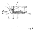
- the cover 1 and the radiator neck 2 are connected to each other by means of a bayonet lock.
- the cover 1 is placed on the radiator neck 2 in the mounting direction 3 until the bayonet cams 5 lie below the start edge of the respectively assigned bayonet curve 5, so that subsequently turning in the direction of the arrow 6, that is to say in the closing direction of rotation, is possible.
- Each bayonet cam 4 then slides in a known manner along the bayonet curve 5, which rises downwards, which leads to a lowering movement of the closure cover 1 superimposed on the rotary movement.
- the latter bears a sealing ring 7 designed as an O-ring 7 at its front end in the direction of attachment 3. As shown in FIG. 5, for example, it lies against a cylindrical inner surface 8 and seals, at least when the bayonet is completely closed thus at this point the gap 9 between the sealing cap 1 and the radiator neck 2.
- each of the two bayonet curves 5 of the exemplary embodiments initially runs approximately in a plane perpendicular to the geometric axis 10 of the radiator connector 2 or at most slightly inclined thereto. This is then followed by the inclined or steeper section, which causes the closing cover 1 to be pulled in in the direction of the arrow 3. The so-called pre-locking position is reached at the transition between these two curve sections (FIG. 6).
- the sealing ring which in the case of two sealing rings designed as O-rings, does not yet form a first O-ring 7 on the cylinder inner surface 8.
- the inner wall of the radiator neck in the area of the closure cover 1 is reduced in a paragraph-like manner.
- the transition takes place e.g. B. via an intermediate cone 13.
- the diameter of the further bore part 14 is selected so that the first O-ring 7 can not rest on it.
- a third sealing ring 19 is provided, which is designed in a known manner as a flat sealing ring and rests on the bead-like opening of the radiator connector 2 when the bayonets are completely closed or is pressed thereon in a sealing manner. In the pre-locking position, this seal is of course relieved or lifted from the mouth opening.
- a conically tapering from the outside in can also be provided, the cone then having to be chosen such that in the case of two O-rings the second O-ring 17 also bears against the radiator socket wall 2 in the pre-locking position.
- the O-ring grooves are designated 21 and 22.
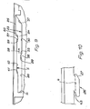
- closure cap 1 and radiator neck 2 there is a counter stroke curve 23 opposite each bayonet curve 5. Due to their axial spacing, the two together form an um External groove 24 running in the direction of the circumference of the connecting piece.
- the groove base can be seen in FIG. 1.
- each outer groove opens at the free radiator nozzle end, the groove mouth being designated 25 in FIG. 1. Its length measured in the circumferential direction corresponds to the length of the bayonet cam 4.
- Each bayonet cam 4 is connected to a counter cam 26, in particular directly, or is produced in one piece in the case of plastic production.
- the counter-cam 26 is then formed by the surface or edge of the assigned bayonet cam 4 pointing in the mounting direction 3 of the sealing cover 1. Seen in the closed direction of rotation 6, this counter cam 26 drops towards the rear, as shown in FIG. 1 of the drawing. This creates at this point a sliding bevel 27 which is of importance when opening the closure cover 1 in the manner explained below.
- the height of bayonet cams 4 and counter-cams 26 together is measured in the axial direction so that both are not greater than the width of the outer groove 24 measured in the axial direction at the narrowest point, although the bayonet engagement at the start of the closing rotary movement is not taken into account is left.
- each bayonet of the bayonet closure is closed in a known manner, the bayonet cam 4 interacting with its assigned bayonet curve 5. Due to the strong friction between the one or more O-rings and the associated wall of the radiator connector 2, the closure cover 1 remains in its lowest position when viewed in the axial direction when the bayonets are opened. The bayonets are not able to exert a pulling action against the arrow 3 on the cover 1. This is also the reason why so far there is no known closure cover which is held on a radiator socket by means of a bayonet closure and is sealed against the radiator socket by means of O-rings.
- each counter cam 26 is first moved along the flat or approximately flat section 28 of the stroke counter curve 23.
- the bayonet cam 6 then moves away from in in the axial direction As seen in the rotational opening direction, the part of the bayonet cam 4 falling off.
- the closure cover 1 does not yet perform any lifting opening movement, or at least not completely. It is only in the interaction of the sliding bevel 27 with the inner lifting section 29 that there is a first partial lifting of the closure cover 1.
- the sealing cap 1 is turned further in the opposite direction of the arrow 6, the sliding bevel 27 then interacting with the outer lifting section 31 and thereby lifting the sealing cap 1 so high that it can be removed from the radiator neck 2 without, at least without any significant force .
- the closure cover is provided with a centering pin 32 which carries the first O-ring 7 in the region of its free end and which also forms the housing for a pressure relief valve.
- a centering pin 32 which carries the first O-ring 7 in the region of its free end and which also forms the housing for a pressure relief valve.
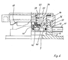
- Each O-ring groove is molded on.
- the same preferably also applies to the valve seat 34 of the pressure relief valve 35 and at least one radial outlet opening 36 on the outflow side of the valve housing wall, via which the medium can pass into the gap 37 between the centering pin 32 or valve housing and the radiator nozzle when the pressure relief valve is open. From there, it arrives in the manner described, even when the radiator cap 1 is firmly closed, via the radial outlet opening
- the closure member of the pressure relief valve 35 is designated 38 (FIG. 6) and is designed in a known manner. It is spring-loaded by means of a helical compression spring 39.
- the vacuum valve 40 is arranged centrally for this purpose.
- its closure member 42 which is loaded by the spring 41, bears against the common sealing ring 43, which at the same time forms the valve seat of the vacuum valve 40.
- the closure member 38 of the pressure relief valve 35 is raised in a known manner, while in the event of negative pressure the closure member 42 of the vacuum relief valve 40 is shifted downward, in each case against the resistance of the loading spring 39 or 41.
- the part 44 of the radiator connector 2 which has the stroke-counter curves 23 is located on a compensating tank 45, but at least on an upper part of such a compensating tank.
- a so-called expansion tank is provided in addition to the cooler, which carries the sealing cover and into which both the cooling water and cooling water additives are poured.
- radiator neck As shown in FIG. 5, it is not only possible to produce this part 44 with the stroke countercurves 23, but also the entire radiator neck 2 in one piece with the expansion tank 45 or an expansion tank upper part.
- the radiator neck according to the embodiments of FIGS. 3 and 4 formed in two parts. While the inner part of the radiator nozzle forms the radiator nozzle part 44 with the stroke opposing curves 23, the bayonet curves 5 are located on a separately produced outer radiator nozzle part 46 or 47.
- the outer radiator neck part 46 (FIG. 3) is made of sheet metal, for example, and is of a known construction. It has a central tubular extension 48, by means of which it is fastened to a central bore 49 of the expansion tank 45 or an upper part of the expansion tank by flanging, a sealing ring or O-ring 50 being connected between the two parts.
- the bayonet curves 5 in the exemplary embodiment according to FIG. 4 are to a certain extent located on an outer collar of a tubular radiator connector part 47 provided with a perforated bottom 51 and inserted centrally in the tubular part 44.
- the inner part 44 of the radiator neck does not necessarily have to be connected to an expansion tank or be part of the same, but that it does so can also be the tubular approach of a radiator upper part or radiator water box.
- the inner part 44 of the connector 2 is made of plastic, as well as the plastic production of the entire cover 1 (with the exception of the springs) is preferred.
- Polypropylene is preferably used for the expansion tank, while the lid is expediently made from polyamide, a highly heat-resistant variant having to be used and glass fiber reinforcement or the like also being provided.
- the part of the cover 1, which carries the two O-rings 7 and 17, can be rotatably supported on the remaining part of the cover 1, in particular on the upper part of the bayonet cams 4, in a manner not shown .
- the medium flowing off under pressure enters the pressure relief valve (35) via at least one opening (44) at the free inner end of the radiator connector (2).
- Each bayonet cam and its associated counter-cam form a movable element along the outer groove of the radiator neck, which is why this outer groove, measured in the axial direction, must be at least as high at every point that the movement of this element is not hindered when the closure cap is attached and when it is released.
- the height of the individual sections is quite different, which results from their special shape and the mutual assignment.
- the bayonet curve also has the otherwise usual task here, namely to pull the closure cover against the neck opening when unscrewing it, so that a seal which may be located between the neck opening and a cover edge is pressed. Even when using O-rings for sealing, an at least partially inclined bayonet curve is necessary in order to achieve the desired sealing between the sealing cover and the radiator nozzle.
- the bayonet curve does not have to extend inclined over its entire length to the neck opening or a plane perpendicular to the longitudinal axis of the neck, rather it is sufficient if only a part of it has such an inclination.
- this is the last section that extends up to the rotary end stop 16.
- the section of the bayonet curve initially reached by the slot mouth 25 runs approximately in FIG. 1 parallel to the mouth level.
- the starting area of this section is opposite the second flat section 30 of the stroke counter-curve 23, which merges smoothly into the outer stroke section 31.
- the two flat sections 28 and 30 of this embodiment lie at different levels in the axial direction of the nozzle.
- the second flat section 30 of the stroke counter-curve 23 lies axially opposite an auxiliary cam 57 pointing into the interior of the socket.
- Such an auxiliary cam 57 is provided on each bayonet curve 5. It is particularly important when opening the cover. If the closure cap 1, which is usually under high excess pressure, is opened, the inner lifting section hosts 29 the release of the first O-ring 27 and thus a connection of the socket interior or the cooler to the outside atmosphere. In this way the overpressure can be released. This process can take a certain amount of time, especially in the case of very high overpressure and a small cross-section.
- the auxiliary cam 57 mentioned is present in the exemplary embodiment according to FIG. 9.
- the counter cam 26 After reaching the pre-locking position with overpressure reduction, the counter cam 26 abuts the auxiliary cam 57, thereby preventing rapid further rotation in the direction of arrow 58.
- the auxiliary cams 57 In order to bring this cover into a rotational position suitable for removal, the auxiliary cams 57 must be overcome. This means that the sealing cover must again make a lowering movement towards the cooler. This is not possible, or at least not readily possible, in the case of excess pressure in the radiator neck.
- the user is thus prevented from "turning" the closure lid in the opening direction 58 quickly and the inattentive user is assisted cam 57 pointed out that he does not turn the lid too quickly, but first waits for the overpressure to release.
- the second flat section 30 of the stroke counter curve 23 is lowered in the manner described.
- This sliding edge of the auxiliary cam 57 is designated 59 and the falling edge 60.
- the oblique edge 61 in FIG. 9 has turned out to be relatively short, in relation to the exemplary embodiment according to FIG. 1, for example. Similar to FIG. 1, the oblique edge 61 of the bayonet curve 5 is followed by an approximately flat section 62, which extends to the auxiliary cam 57, the latter then merging into the slot mouth 25.
- a rear bevel 63 is particularly important, which is located at the rear end of the counter cam 26 or this element in the opening direction 58. It preferably runs approximately parallel to the sliding counter bevel 27 of the counter cam 26.
Landscapes
- Engineering & Computer Science (AREA)
- Mechanical Engineering (AREA)
- Chemical & Material Sciences (AREA)
- Combustion & Propulsion (AREA)
- General Engineering & Computer Science (AREA)
- Closures For Containers (AREA)
- Heat-Exchange Devices With Radiators And Conduit Assemblies (AREA)
Applications Claiming Priority (4)
| Application Number | Priority Date | Filing Date | Title |
|---|---|---|---|
| DE8814599U DE8814599U1 (fr) | 1988-11-23 | 1988-11-23 | |
| DE8814599U | 1988-11-23 | ||
| DE8901826U | 1989-02-16 | ||
| DE8901826U DE8901826U1 (fr) | 1988-11-23 | 1989-02-16 |
Publications (4)
| Publication Number | Publication Date |
|---|---|
| EP0370234A2 true EP0370234A2 (fr) | 1990-05-30 |
| EP0370234A3 EP0370234A3 (en) | 1990-07-04 |
| EP0370234B1 EP0370234B1 (fr) | 1993-09-01 |
| EP0370234B2 EP0370234B2 (fr) | 1996-07-17 |
Family
ID=25953811
Family Applications (1)
| Application Number | Title | Priority Date | Filing Date |
|---|---|---|---|
| EP89119492A Expired - Lifetime EP0370234B2 (fr) | 1988-11-23 | 1989-10-20 | Gorge de remplissage de radiateur avec bouchon |
Country Status (4)
| Country | Link |
|---|---|
| US (1) | US5071020A (fr) |
| EP (1) | EP0370234B2 (fr) |
| DE (2) | DE8901826U1 (fr) |
| ES (1) | ES2045337T5 (fr) |
Cited By (3)
| Publication number | Priority date | Publication date | Assignee | Title |
|---|---|---|---|---|
| EP0658483A1 (fr) * | 1993-12-17 | 1995-06-21 | MAGNETI MARELLI CLIMATIZZAZIONE S.r.l. | Réservoir collecteur pour échangeurs de chaleur pour véhicule à moteur avec bouchon d'aération |
| WO2002030791A1 (fr) * | 2000-10-13 | 2002-04-18 | Poetzsch Holger | Conteneur de transport |
| US7631619B2 (en) | 2005-01-31 | 2009-12-15 | Behr Gmbh & Co. Kg | Cooling agent compensation tank for a cooling circuit |
Families Citing this family (42)
| Publication number | Priority date | Publication date | Assignee | Title |
|---|---|---|---|---|
| DE4209534C2 (de) * | 1991-03-25 | 1994-12-01 | Aisin Seiki | Kappe zum Verschließen eines Speichertanks |
| DE4339663A1 (de) * | 1993-11-22 | 1995-05-24 | Reutter Metallwaren | Auf einen Behälterstutzen aufschraubbarer Verschlußdeckel |
| US5680954A (en) * | 1994-08-10 | 1997-10-28 | Cummins Engine Company, Inc. | Oil fill cap |
| US5603425A (en) * | 1995-03-17 | 1997-02-18 | Western Thomson Controls Limited | Radiator cap |
| US6314808B1 (en) | 1996-02-27 | 2001-11-13 | Felsted Products Llc | Fluid level measuring device |
| US5699922A (en) * | 1996-05-21 | 1997-12-23 | Mhd Corporation | Detachable closure system for an open-ended tubular member |
| EP1070009B1 (fr) * | 1997-01-16 | 2007-08-29 | Stant Manufacturing Inc. | Bouchon de goulot de remplissage a fermeture rapide |
| US6221089B1 (en) * | 1997-07-07 | 2001-04-24 | International Technidyne Corporation | Skin incision device with compression spring assembly |
| EP1005606B1 (fr) * | 1997-08-21 | 2002-12-11 | Tesma International Inc. | Ensemble bouchon pour recipient refrigerant |
| US6230918B1 (en) * | 1999-01-21 | 2001-05-15 | Stant Manufacturing Inc. | Quick-on filler neck cap |
| AT4061U1 (de) * | 1999-09-08 | 2001-01-25 | Tesma Motoren Getriebetechnik | Verschlussstopfen für einen füllstutzen eines kraftstoffbehälters |
| GB2360512A (en) * | 2000-03-20 | 2001-09-26 | Rover Group | Pressure control valve for cooling system |
| US6644390B2 (en) * | 2000-05-09 | 2003-11-11 | General Motors Corporation | Methods and apparatus for preventing the inadvertent, uncontrolled discharge of pressurized radiator fluid |
| AT4444U1 (de) * | 2000-05-23 | 2001-07-25 | Tesma Motoren Getriebetechnik | Tankverschluss |
| AU2002220506A1 (en) * | 2000-10-28 | 2002-05-06 | Robert Bosch G.M.B.H | Jointless wiper blade, in particular for a motor vehicle |
| JP2002179120A (ja) * | 2000-12-19 | 2002-06-26 | Om Kogyo Kk | 給油口キャップ |
| DE10101521A1 (de) * | 2001-01-12 | 2002-07-18 | Bosch Gmbh Robert | Getriebe-Antriebseinheit |
| JP2002228028A (ja) * | 2001-01-31 | 2002-08-14 | Toyo Radiator Co Ltd | ラジエータのプレッシャバルブ付きキャップ |
| US6935044B2 (en) * | 2001-06-13 | 2005-08-30 | Orscheln Products Llc | Connection system for a fluid level measuring device |
| US6988403B2 (en) * | 2001-10-01 | 2006-01-24 | Orscheln Products Llc | Fluid level measuring device |
| EP1463923A2 (fr) * | 2002-01-09 | 2004-10-06 | Orscheln Products LLC | Dispositif de mesure de niveau de liquide |
| DE10359767B4 (de) * | 2003-12-19 | 2006-01-19 | Dr.Ing.H.C. F. Porsche Ag | Kraftfahrzeug |
| US7510053B2 (en) * | 2004-07-23 | 2009-03-31 | Skf Usa Inc. | Plug for main oil gallery |
| US20070108211A1 (en) * | 2005-11-14 | 2007-05-17 | Gem Products, Inc. | Fill system for fuel and liquid |
| KR101451221B1 (ko) * | 2008-08-27 | 2014-10-15 | 한라비스테온공조 주식회사 | 라디에이터 캡 |
| US8177094B2 (en) * | 2008-12-23 | 2012-05-15 | Captech Ltd. | Pump lid and containers employing such |
| US8091742B2 (en) * | 2008-12-23 | 2012-01-10 | Captech Ltd. | Pump lid |
| US8920956B2 (en) | 2010-08-23 | 2014-12-30 | Lg Chem, Ltd. | Battery system and manifold assembly having a manifold member and a connecting fitting |
| US8469404B2 (en) | 2010-08-23 | 2013-06-25 | Lg Chem, Ltd. | Connecting assembly |
| US8353315B2 (en) * | 2010-08-23 | 2013-01-15 | Lg Chem, Ltd. | End cap |
| US8758922B2 (en) | 2010-08-23 | 2014-06-24 | Lg Chem, Ltd. | Battery system and manifold assembly with two manifold members removably coupled together |
| US8974934B2 (en) | 2012-08-16 | 2015-03-10 | Lg Chem, Ltd. | Battery module |
| KR101500136B1 (ko) * | 2013-09-06 | 2015-03-06 | 현대자동차주식회사 | 차량의 오주유 방지장치 |
| KR101459949B1 (ko) * | 2013-09-26 | 2014-11-07 | 현대자동차주식회사 | 냉각수 비산 방지 타입 서지탱크 |
| JP5767735B2 (ja) * | 2014-05-07 | 2015-08-19 | 株式会社ティラド | ラジエータキャップ |
| US9856777B2 (en) * | 2014-12-08 | 2018-01-02 | Toledo Molding & Die, Inc. | Dual chamber coolant reservoir |
| JP5753938B2 (ja) * | 2014-12-15 | 2015-07-22 | 株式会社ティラド | 樹脂製ラジエータキャップおよびその製造方法 |
| US9573752B2 (en) * | 2014-12-24 | 2017-02-21 | Drink Saporé Inc. | Liquid container apparatus |
| CN104633189A (zh) * | 2014-12-29 | 2015-05-20 | 中国科学院等离子体物理研究所 | 真空安全阀 |
| FR3083304A1 (fr) * | 2018-06-29 | 2020-01-03 | Valeo Systemes Thermiques | Bouchon pour une boite collectrice |
| US11383901B2 (en) * | 2018-12-05 | 2022-07-12 | Bemis Manufacturing Company | Pressure relief cap |
| JP2020193610A (ja) * | 2019-05-30 | 2020-12-03 | 株式会社デンソー | リザーブタンク |
Citations (5)
| Publication number | Priority date | Publication date | Assignee | Title |
|---|---|---|---|---|
| US1738893A (en) * | 1928-10-11 | 1929-12-10 | John O Grady | Container cover |
| US1896272A (en) * | 1930-08-08 | 1933-02-07 | W B Jarvis Company | Closure for filler necks and the like |
| US3216608A (en) * | 1963-09-12 | 1965-11-09 | Dole Valve Co | Pressure cap for sealed cooling system |
| FR2258315A1 (fr) * | 1974-01-17 | 1975-08-18 | Cooper Alfred | |
| US4196822A (en) * | 1971-10-29 | 1980-04-08 | Avrea Walter C | Monolithic radiator cap for sealed pressurized cooling system |
Family Cites Families (6)
| Publication number | Priority date | Publication date | Assignee | Title |
|---|---|---|---|---|
| US1456333A (en) * | 1922-04-12 | 1923-05-22 | Einer M Nelson | Radiator cap |
| US1550302A (en) * | 1923-08-25 | 1925-08-18 | Simplex Cap Company | Closure |
| US3878965A (en) * | 1974-05-13 | 1975-04-22 | Stant Mfg Co | Pressure-vacuum relief vehicle radiator cap with free-turning shell |
| DE3150231A1 (de) * | 1981-12-18 | 1983-06-30 | Reutter Metallwarenfabrik GmbH, 7050 Waiblingen | Verschlussdeckel, insbesondere fuer einen kuehlerstutzen eines kraftfahrzeugs |
| US4498599A (en) * | 1983-08-15 | 1985-02-12 | Avrea Walter C | Closure and valving apparatus |
| US4762244A (en) * | 1987-09-23 | 1988-08-09 | Thermo King Corporation | Radiator overflow container |
-
1989
- 1989-02-16 DE DE8901826U patent/DE8901826U1/de not_active Expired
- 1989-10-20 ES ES89119492T patent/ES2045337T5/es not_active Expired - Lifetime
- 1989-10-20 DE DE89119492T patent/DE58905459D1/de not_active Expired - Fee Related
- 1989-10-20 EP EP89119492A patent/EP0370234B2/fr not_active Expired - Lifetime
- 1989-11-16 US US07/438,350 patent/US5071020A/en not_active Expired - Fee Related
Patent Citations (5)
| Publication number | Priority date | Publication date | Assignee | Title |
|---|---|---|---|---|
| US1738893A (en) * | 1928-10-11 | 1929-12-10 | John O Grady | Container cover |
| US1896272A (en) * | 1930-08-08 | 1933-02-07 | W B Jarvis Company | Closure for filler necks and the like |
| US3216608A (en) * | 1963-09-12 | 1965-11-09 | Dole Valve Co | Pressure cap for sealed cooling system |
| US4196822A (en) * | 1971-10-29 | 1980-04-08 | Avrea Walter C | Monolithic radiator cap for sealed pressurized cooling system |
| FR2258315A1 (fr) * | 1974-01-17 | 1975-08-18 | Cooper Alfred |
Cited By (3)
| Publication number | Priority date | Publication date | Assignee | Title |
|---|---|---|---|---|
| EP0658483A1 (fr) * | 1993-12-17 | 1995-06-21 | MAGNETI MARELLI CLIMATIZZAZIONE S.r.l. | Réservoir collecteur pour échangeurs de chaleur pour véhicule à moteur avec bouchon d'aération |
| WO2002030791A1 (fr) * | 2000-10-13 | 2002-04-18 | Poetzsch Holger | Conteneur de transport |
| US7631619B2 (en) | 2005-01-31 | 2009-12-15 | Behr Gmbh & Co. Kg | Cooling agent compensation tank for a cooling circuit |
Also Published As
| Publication number | Publication date |
|---|---|
| DE58905459D1 (de) | 1993-10-07 |
| ES2045337T5 (es) | 1996-11-16 |
| EP0370234B2 (fr) | 1996-07-17 |
| ES2045337T3 (es) | 1994-01-16 |
| EP0370234B1 (fr) | 1993-09-01 |
| DE8901826U1 (fr) | 1989-04-06 |
| EP0370234A3 (en) | 1990-07-04 |
| US5071020A (en) | 1991-12-10 |
Similar Documents
| Publication | Publication Date | Title |
|---|---|---|
| EP0370234B1 (fr) | Gorge de remplissage de radiateur avec bouchon | |
| DE3146824C2 (de) | "Verschlußdeckel, insbesondere für einen Kraftstofftank" | |
| EP0760789B1 (fr) | Ensemble bouchon fixable sur le col d'un reservoir | |
| DE2322564C2 (de) | Verschlußdeckel | |
| DE10125037B4 (de) | Tankverschluß | |
| WO2003062613A1 (fr) | Bouchon de fermeture pour radiateur de vehicule automobile | |
| WO2012139631A1 (fr) | Tubulure de remplissage pour un réservoir de liquide, en particulier un réservoir d'urée, sur des véhicules automobiles | |
| DE3008002A1 (de) | Verschlussdeckel insbesondere fuer einen kraftfahrzeugkuehler | |
| EP1303687B1 (fr) | Bouchon de fermeture a systeme de blocage en rotation | |
| EP1268993B1 (fr) | Bouchon de fermeture | |
| DE2444477A1 (de) | Verschlussdeckel mit zur sicherung nach aussen zu abgedichtet eingesetztem riegelschloss | |
| DE2308669C3 (de) | Verschluß für Flüssigkeitsbehälter | |
| EP0943477B1 (fr) | Fermeture pour réservoir de carburant | |
| DE10132661A1 (de) | Verschlussdeckel mit Abschraubsicherung | |
| EP0102083B1 (fr) | Embout autoverrouillant pour conduit de remplissage d'un réservoir de carburant | |
| DE3150231A1 (de) | Verschlussdeckel, insbesondere fuer einen kuehlerstutzen eines kraftfahrzeugs | |
| DE1812592A1 (de) | Selbsttaetig arbeitendes Entleerungsventil | |
| DE10224245A1 (de) | Absperrventil für einen druckbeaufschlagten Behälter sowie Behälter | |
| DE19753592A1 (de) | Verschlußdeckel | |
| EP0696545A1 (fr) | Valve pour la distribution de fluides sous pression | |
| DE19732885B4 (de) | Verschlussdeckel mit Sicherheitsverriegelung für einen Behälter | |
| DE3327804C1 (de) | Verschluß für zweiteilige Gehäuse zum Filtern von Flüssigkeiten | |
| DE2642641C3 (de) | Vorläufige Schutzkappe zur Anbringung an einem Absperrventil | |
| DE8528368U1 (de) | Reduziereinsatz für einen Tankfüll-Stutzen | |
| EP3001081B1 (fr) | Vanne équerre doté d'un volant à main |
Legal Events
| Date | Code | Title | Description |
|---|---|---|---|
| PUAI | Public reference made under article 153(3) epc to a published international application that has entered the european phase |
Free format text: ORIGINAL CODE: 0009012 |
|
| PUAL | Search report despatched |
Free format text: ORIGINAL CODE: 0009013 |
|
| AK | Designated contracting states |
Kind code of ref document: A2 Designated state(s): DE ES FR GB IT |
|
| AK | Designated contracting states |
Kind code of ref document: A3 Designated state(s): DE ES FR GB IT |
|
| 17P | Request for examination filed |
Effective date: 19900528 |
|
| 17Q | First examination report despatched |
Effective date: 19910902 |
|
| GRAA | (expected) grant |
Free format text: ORIGINAL CODE: 0009210 |
|
| AK | Designated contracting states |
Kind code of ref document: B1 Designated state(s): DE ES FR GB IT |
|
| ET | Fr: translation filed | ||
| REF | Corresponds to: |
Ref document number: 58905459 Country of ref document: DE Date of ref document: 19931007 |
|
| ITF | It: translation for a ep patent filed |
Owner name: MODIANO & ASSOCIATI S.R |
|
| REG | Reference to a national code |
Ref country code: ES Ref legal event code: FG2A Ref document number: 2045337 Country of ref document: ES Kind code of ref document: T5 |
|
| GBT | Gb: translation of ep patent filed (gb section 77(6)(a)/1977) |
Effective date: 19940110 |
|
| PLBI | Opposition filed |
Free format text: ORIGINAL CODE: 0009260 |
|
| 26 | Opposition filed |
Opponent name: BLAU GMBH Effective date: 19940531 |
|
| PLAW | Interlocutory decision in opposition |
Free format text: ORIGINAL CODE: EPIDOS IDOP |
|
| PUAH | Patent maintained in amended form |
Free format text: ORIGINAL CODE: 0009272 |
|
| STAA | Information on the status of an ep patent application or granted ep patent |
Free format text: STATUS: PATENT MAINTAINED AS AMENDED |
|
| 27A | Patent maintained in amended form |
Effective date: 19960717 |
|
| AK | Designated contracting states |
Kind code of ref document: B2 Designated state(s): DE ES FR GB IT |
|
| GBTA | Gb: translation of amended ep patent filed (gb section 77(6)(b)/1977) |
Effective date: 19960717 |
|
| ITF | It: translation for a ep patent filed |
Owner name: MODIANO & ASSOCIATI S.R.L. |
|
| REG | Reference to a national code |
Ref country code: ES Ref legal event code: DC2A Kind code of ref document: T5 Effective date: 19961010 |
|
| ET3 | Fr: translation filed ** decision concerning opposition | ||
| PGFP | Annual fee paid to national office [announced via postgrant information from national office to epo] |
Ref country code: ES Payment date: 20001024 Year of fee payment: 12 |
|
| PGFP | Annual fee paid to national office [announced via postgrant information from national office to epo] |
Ref country code: FR Payment date: 20011009 Year of fee payment: 13 |
|
| REG | Reference to a national code |
Ref country code: GB Ref legal event code: IF02 |
|
| PG25 | Lapsed in a contracting state [announced via postgrant information from national office to epo] |
Ref country code: ES Free format text: LAPSE BECAUSE OF NON-PAYMENT OF DUE FEES Effective date: 20021021 |
|
| PGFP | Annual fee paid to national office [announced via postgrant information from national office to epo] |
Ref country code: GB Payment date: 20021025 Year of fee payment: 14 |
|
| PG25 | Lapsed in a contracting state [announced via postgrant information from national office to epo] |
Ref country code: FR Free format text: LAPSE BECAUSE OF NON-PAYMENT OF DUE FEES Effective date: 20030630 |
|
| REG | Reference to a national code |
Ref country code: FR Ref legal event code: ST |
|
| PG25 | Lapsed in a contracting state [announced via postgrant information from national office to epo] |
Ref country code: GB Free format text: LAPSE BECAUSE OF NON-PAYMENT OF DUE FEES Effective date: 20031020 |
|
| PGFP | Annual fee paid to national office [announced via postgrant information from national office to epo] |
Ref country code: DE Payment date: 20031218 Year of fee payment: 15 |
|
| REG | Reference to a national code |
Ref country code: ES Ref legal event code: FD2A Effective date: 20031112 |
|
| GBPC | Gb: european patent ceased through non-payment of renewal fee |
Effective date: 20031020 |
|
| PG25 | Lapsed in a contracting state [announced via postgrant information from national office to epo] |
Ref country code: DE Free format text: LAPSE BECAUSE OF NON-PAYMENT OF DUE FEES Effective date: 20050503 |
|
| PG25 | Lapsed in a contracting state [announced via postgrant information from national office to epo] |
Ref country code: IT Free format text: LAPSE BECAUSE OF NON-PAYMENT OF DUE FEES;WARNING: LAPSES OF ITALIAN PATENTS WITH EFFECTIVE DATE BEFORE 2007 MAY HAVE OCCURRED AT ANY TIME BEFORE 2007. THE CORRECT EFFECTIVE DATE MAY BE DIFFERENT FROM THE ONE RECORDED. Effective date: 20051020 |
|
| PLAB | Opposition data, opponent's data or that of the opponent's representative modified |
Free format text: ORIGINAL CODE: 0009299OPPO |