EP0368070B1 - Dispositif manuel pour appliquer un film d'un ruban porteur sur un substrat - Google Patents
Dispositif manuel pour appliquer un film d'un ruban porteur sur un substrat Download PDFInfo
- Publication number
- EP0368070B1 EP0368070B1 EP89119665A EP89119665A EP0368070B1 EP 0368070 B1 EP0368070 B1 EP 0368070B1 EP 89119665 A EP89119665 A EP 89119665A EP 89119665 A EP89119665 A EP 89119665A EP 0368070 B1 EP0368070 B1 EP 0368070B1
- Authority
- EP
- European Patent Office
- Prior art keywords
- spool
- take
- housing
- manual device
- edge
- Prior art date
- Legal status (The legal status is an assumption and is not a legal conclusion. Google has not performed a legal analysis and makes no representation as to the accuracy of the status listed.)
- Expired - Lifetime
Links
Images

Classifications
-
- B—PERFORMING OPERATIONS; TRANSPORTING
- B65—CONVEYING; PACKING; STORING; HANDLING THIN OR FILAMENTARY MATERIAL
- B65H—HANDLING THIN OR FILAMENTARY MATERIAL, e.g. SHEETS, WEBS, CABLES
- B65H35/00—Delivering articles from cutting or line-perforating machines; Article or web delivery apparatus incorporating cutting or line-perforating devices, e.g. adhesive tape dispensers
- B65H35/04—Delivering articles from cutting or line-perforating machines; Article or web delivery apparatus incorporating cutting or line-perforating devices, e.g. adhesive tape dispensers from or with transverse cutters or perforators
- B65H35/06—Delivering articles from cutting or line-perforating machines; Article or web delivery apparatus incorporating cutting or line-perforating devices, e.g. adhesive tape dispensers from or with transverse cutters or perforators from or with blade, e.g. shear-blade, cutters or perforators
-
- B—PERFORMING OPERATIONS; TRANSPORTING
- B65—CONVEYING; PACKING; STORING; HANDLING THIN OR FILAMENTARY MATERIAL
- B65H—HANDLING THIN OR FILAMENTARY MATERIAL, e.g. SHEETS, WEBS, CABLES
- B65H37/00—Article or web delivery apparatus incorporating devices for performing specified auxiliary operations
- B65H37/002—Web delivery apparatus, the web serving as support for articles, material or another web
- B65H37/005—Hand-held apparatus
- B65H37/007—Applicators for applying coatings, e.g. correction, colour or adhesive coatings
-
- Y—GENERAL TAGGING OF NEW TECHNOLOGICAL DEVELOPMENTS; GENERAL TAGGING OF CROSS-SECTIONAL TECHNOLOGIES SPANNING OVER SEVERAL SECTIONS OF THE IPC; TECHNICAL SUBJECTS COVERED BY FORMER USPC CROSS-REFERENCE ART COLLECTIONS [XRACs] AND DIGESTS
- Y10—TECHNICAL SUBJECTS COVERED BY FORMER USPC
- Y10T—TECHNICAL SUBJECTS COVERED BY FORMER US CLASSIFICATION
- Y10T156/00—Adhesive bonding and miscellaneous chemical manufacture
- Y10T156/17—Surface bonding means and/or assemblymeans with work feeding or handling means
- Y10T156/1788—Work traversing type and/or means applying work to wall or static structure
- Y10T156/1795—Implement carried web supply
-
- Y—GENERAL TAGGING OF NEW TECHNOLOGICAL DEVELOPMENTS; GENERAL TAGGING OF CROSS-SECTIONAL TECHNOLOGIES SPANNING OVER SEVERAL SECTIONS OF THE IPC; TECHNICAL SUBJECTS COVERED BY FORMER USPC CROSS-REFERENCE ART COLLECTIONS [XRACs] AND DIGESTS
- Y10—TECHNICAL SUBJECTS COVERED BY FORMER USPC
- Y10T—TECHNICAL SUBJECTS COVERED BY FORMER US CLASSIFICATION
- Y10T156/00—Adhesive bonding and miscellaneous chemical manufacture
- Y10T156/18—Surface bonding means and/or assembly means with handle or handgrip
-
- Y—GENERAL TAGGING OF NEW TECHNOLOGICAL DEVELOPMENTS; GENERAL TAGGING OF CROSS-SECTIONAL TECHNOLOGIES SPANNING OVER SEVERAL SECTIONS OF THE IPC; TECHNICAL SUBJECTS COVERED BY FORMER USPC CROSS-REFERENCE ART COLLECTIONS [XRACs] AND DIGESTS
- Y10—TECHNICAL SUBJECTS COVERED BY FORMER USPC
- Y10T—TECHNICAL SUBJECTS COVERED BY FORMER US CLASSIFICATION
- Y10T156/00—Adhesive bonding and miscellaneous chemical manufacture
- Y10T156/19—Delaminating means
- Y10T156/1994—Means for delaminating from release surface
Definitions
- the empty diameter of the take-up reel in the device according to the invention is always larger than the maximum diameter (measured with a full supply of tape) of the supply reel, which is why the unwinding speed of the supply reel is always greater than the winding speed of the take-up reel, so that with respect to the drive conditions there is always a positive slip of the take-up reel relative to Take-up reel and thus always the required tape tension is ensured, which makes the use of a transmission gear completely unnecessary, since under no operating conditions it is necessary to build up an acceleration via a gear.
- the wedge shape of the housing in the device according to the invention also allows standing up, with little space being required on the storage surface (similar to adhesive bottles).
- the special arrangement of both spools ensures that the carrier tape on the dispenser spool can always be pulled up freely and freely from the winding because the supply spool there lies completely outside the interior of the spool core of the winding spool.
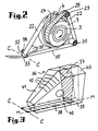
- the supply spool 3 has a spool core 5 and the supply spool 4 has a spool core 6, with a tape supply 7 being attached to the spool core 5, which builds up again on the take-up spool 4 in the form of an increasing supply of tapes 8 as it unwinds.
- 1 shows the initial tape supply 7 on the supply reel 3, i. H. the full tape supply 7 (maximum reel diameter), with no tape supply being wound up on the take-up reel 4 yet.
- the tape supply 8 shown in dash-dotted lines in FIG. 1 represents the conditions that occur when the entire tape supply 7 is wound off the supply reel 3 and completely wound onto the take-up reel 4.
- the supply reel 3 is in turn seated on a bearing journal 12 which is arranged on the housing side wall 1 and projects into the interior of the housing.
- This bearing journal 12 has an end surface 13 which is inclined in cross section and inclined by an angle ⁇ to the central plane AA of the coil, the angle ⁇ being chosen so that the central support bolt 10 projecting from the take-up reel 4 protrudes with its bearing journal attached at the end 20 is made possible. This means that the angle ⁇ must be chosen equal to the angle ⁇ .
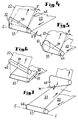
- the position of the application bar CC (corresponding to the position of the pressure edge 33 at the end of the application foot 31), in which the film coating of the carrier tape 22 is transferred to a substrate, is indicated by dash-dotted lines parallel to the bottom 39 becomes.
- This plane lies at right angles to the center plane through the bisector of the angle of attack ⁇ formed by planes AA and BB (i.e. in the housing illustration of FIG. 1: at right angles to the perpendicular center plane of the overall housing) and also runs through the cutting edge S which is at the interface of the planes AA and BB occurs. 1 there is still with thin lines the inlet of the coated carrier tape 22 from the supply reel 3 to the level of the tape section 35 (see FIG.
- leading edge 34 and the pressure edge 33 can be achieved, for example, by the wedge-shaped design of the pressure element 32 which can be seen in FIG.
- the lifting of the tape end indicated in FIG. 2 at the end of the tape section 22 running onto the take-up reel 4 is not intended to represent an actual lifting, but only to clarify what is there on the reel serve as the end of the band.
Landscapes
- Adhesive Tape Dispensing Devices (AREA)
- Coating Apparatus (AREA)
- Winding Of Webs (AREA)
- Supply And Installment Of Electrical Components (AREA)
- Traffic Control Systems (AREA)
- Adhesives Or Adhesive Processes (AREA)
- On-Site Construction Work That Accompanies The Preparation And Application Of Concrete (AREA)
- Replacement Of Web Rolls (AREA)
Claims (16)
- Dispositif manuel pour transférer un film d'un ruban porteur sur un substrat, selon lequel dans un boîtier le ruban porteur est dévidé d'une bobine d'émission de petites dimensions par-dessus un bord applicateur d'un talon applicateur prévu à la base d'un boîtier et en saillie vers l'extérieur pour revenir à partir de celui-ci dans le boîtier et arriver sur une bobine réceptrice plus grande, la bobine émettrice et la bobine réceptrice étant couplées l'une à l'autre par un embrayage à friction agissant dans le sens de rotation, et des moyens de guidage prévus sur le boîtier pour guider le ruban porteur, dispositif caractérisé en ce que la bobine émettrice (3) et la bobine réceptrice (4) sont juxtaposées axialement en faisant entre elles un angle aigu (α), la bobine émettrice (3) pénétrant dans la partie inférieure de la cavité (24) ouverte de son côté du corps (6) de la bobine réceptrice (4) plus grande, alors qu'elle se trouve complètement à l'extérieur, au niveau de sa partie supérieure, l'embrayage à friction (25-27) étant situé dans la zone intermédiaire entre les deux bobines (3, 4),
le moyen de guidage du ruban porteur (22) est prévu entre la bobine émettrice (3) et le talon applicateur (31) et le bord applicateur (33) comporte en aval un bord de guidage (34) incliné d'un angle (δ) pour dévier latéralement le ruban porteur (22) en direction de la bobine réceptrice (4). - Dispositif manuel selon la revendication 1, caractérisé en ce que l'angle de positionnement (α) entre les deux bobines (3, 4) est compris entre 10° et 15°, notamment égal à 12°.
- Dispositif manuel selon la revendication 1 ou 2, caractérisé en ce que le talon applicateur (31) est réalisé et est disposé pour que son bord applicateur (33) se trouve dans un plan perpendiculaire à la bissectrice de l'angle (α) compris entre les deux bobines (3, 4) et passe par la ligne d'intersection commune (S) des plans médians radiaux (A, B) des deux bobines (3, 4).
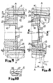
- Dispositif manuel selon l'une des revendications 1 à 3, caractérisé en ce que l'embrayage à friction (25, 26, 27) est réalisé avec une transmission de force, active, à l'intérieur du corps (5) de la petite bobine émettrice (3).
- Dispositif manuel selon l'une des revendications 1 à 4, caractérisé en ce que la bobine réceptrice (4) comporte un goujon d'appui (10) central, creux d'un côté, en saillie de la cavité (24) de son corps de bobine (6) et pénétrant dans la cavité (23) du corps (5) de la bobine émettrice (3), ce goujon d'appui venant avec un tourillon de palier (20) qu'il porte à son extrémité en saillie dans une cavité de palier (21) sur la paroi latérale associée (1) et son autre extrémité vient par son perçage intérieur (48) ouvert de ce côté sur un tourillon de palier (11) de l'autre paroi de boîtier (2).
- Dispositif manuel selon la revendication 5, caractérisé en ce qu'autour du goujon d'appui (10) il y a plusieurs doigts d'embrayage (25) escamotables élastiquement dans la direction radiale, qui viennent en saillie en s'écartant en direction de la bobine émettrice (3), ces doigts (lamelles) ayant à leurs extrémités des dents d'embrayage (26) radialement en saillie vers l'extérieur et qui viennent prendre au moins partiellement dans une denture intérieure (27) correspondante prévue sur le corps (5) de la bobine émettrice (3).
- Dispositif manuel selon l'une des revendications 1 à 6, caractérisé en ce que la bobine émettrice (3) comporte sur son côté tourné vers la bobine réceptrice (4), un disque formant bord (16) dont la surface extérieure tournée vers la bobine réceptrice (4) comporte un collet d'appui (17) périphérique circulaire, qui, dans la zone inférieure en prise des deux bobines (3, 4) s'appuie contre un appui de butée (18, 19) périphérique également annulaire, de forme appropriée, dans la cavité (24) du corps (6) de la bobine réceptrice (4), cet appui étant prévu sur le disque de support (9), radial.
- Dispositif manuel selon l'une des revendications 1 à 7, caractérisé en ce que le moyen de guidage est constitué par au moins deux tourillons de renvoi (29, 30) cylindriques.
- Dispositif manuel selon la revendication 8, caractérisé en ce que les tourillons de renvoi (29, 30) sont montés à rotation.
- Dispositif manuel selon l'une des revendications 1 à 9, caractérisé en ce que le bord de guidage (34) est réalisé directement sur le talon applicateur (31).
- Dispositif manuel selon la revendication 10, caractérisé en ce qu'à l'extrémité du talon applicateur (31), pour réaliser le bord applicateur (33) et le bord de guidage (34), il est prévu un longeron applicateur (32) en forme de tronc de cône (47) disposé transversalement au chemin de guidage du ruban et situé en biais.
- Dispositif manuel selon l'une des revendications 1 à 9, caractérisé en ce que le bord de guidage (34) est prévu sur une pièce indépendante (45, 47) en aval du talon applicateur (31).
- Dispositif manuel selon la revendication 12, caractérisé en ce que le bord de guidage (34) est formé par un tourillon de renvoi (45) cylindrique.
- Dispositif manuel selon l'une des revendications 1 à 13, caractérisé en ce que la paroi latérale (1, 2) voisine de chaque bobine (3, 4) est chaque fois parallèle au plan médian (A-A, B-B) de la bobine (3, 4) correspondante.
- Dispositif manuel selon la revendication 3 ou 4, caractérisé en ce que les axes des tourillons de renvoi (29, 30) sont parallèles à l'axe de la bobine émettrice (3).
- Dispositif manuel selon l'une des revendications 1 à 15, caractérisé en ce que la bobine émettrice (3), la bobine réceptrice (4), le moyen de guidage (29, 30) ainsi que l'embrayage à friction (25, 26, 27) sont logés dans une cassette interchangeable qui porte en même temps le talon applicateur (31) avec le longeron applicateur (32) et le bord applicateur (33) ainsi que le bord de guidage (34).
Priority Applications (1)
| Application Number | Priority Date | Filing Date | Title |
|---|---|---|---|
| AT89119665T ATE97100T1 (de) | 1988-11-05 | 1989-10-24 | Handgeraet zum ubertragen eines filmes von einem traegerband auf ein substrat. |
Applications Claiming Priority (2)
| Application Number | Priority Date | Filing Date | Title |
|---|---|---|---|
| DE3837621 | 1988-11-05 | ||
| DE3837621A DE3837621C1 (fr) | 1988-11-05 | 1988-11-05 |
Publications (3)
| Publication Number | Publication Date |
|---|---|
| EP0368070A2 EP0368070A2 (fr) | 1990-05-16 |
| EP0368070A3 EP0368070A3 (fr) | 1991-01-30 |
| EP0368070B1 true EP0368070B1 (fr) | 1993-11-10 |
Family
ID=6366578
Family Applications (1)
| Application Number | Title | Priority Date | Filing Date |
|---|---|---|---|
| EP89119665A Expired - Lifetime EP0368070B1 (fr) | 1988-11-05 | 1989-10-24 | Dispositif manuel pour appliquer un film d'un ruban porteur sur un substrat |
Country Status (16)
| Country | Link |
|---|---|
| US (1) | US5006184A (fr) |
| EP (1) | EP0368070B1 (fr) |
| JP (1) | JPH0633127B2 (fr) |
| KR (1) | KR940000052B1 (fr) |
| AR (1) | AR244134A1 (fr) |
| AT (1) | ATE97100T1 (fr) |
| AU (1) | AU605699B2 (fr) |
| BR (1) | BR8905720A (fr) |
| DE (2) | DE3837621C1 (fr) |
| DK (1) | DK167609B1 (fr) |
| ES (1) | ES2046431T3 (fr) |
| FI (1) | FI895212A0 (fr) |
| MX (1) | MX172499B (fr) |
| NO (1) | NO172531C (fr) |
| PT (1) | PT92198B (fr) |
| ZA (1) | ZA898289B (fr) |
Families Citing this family (36)
| Publication number | Priority date | Publication date | Assignee | Title |
|---|---|---|---|---|
| US4980011A (en) * | 1988-01-27 | 1990-12-25 | Minnesota Mining And Manufacturing Company | Automated liner removing transfer tape applicator |
| DE4104331A1 (de) * | 1991-02-13 | 1992-08-27 | Henkel Kgaa | Einachsiger kleberoller |
| GB2254289B (en) * | 1991-04-05 | 1995-03-22 | Gerber Garment Technology Inc | Readily transferrable adherent tape and methods of use and making |
| EP0606477A4 (fr) * | 1991-10-02 | 1994-11-09 | Fuji Kagaku Shikogyo | Dispositif pour transferer un film de revetement. |
| US5281298A (en) * | 1992-03-03 | 1994-01-25 | The Gillette Company | Film transfer device |
| US5310437A (en) * | 1992-10-15 | 1994-05-10 | The Gillette Company | Single spool correction tape dispenser |
| US5310445A (en) * | 1992-10-15 | 1994-05-10 | The Gillette Company | Tape dispenser |
| GB2275042B (en) * | 1993-02-10 | 1995-10-25 | Gillette Co | Correction tape dispenser |
| US5393368A (en) * | 1993-02-10 | 1995-02-28 | The Gillette Company | Correction tape dispenser |
| JP2869855B2 (ja) * | 1995-03-28 | 1999-03-10 | 株式会社トンボ鉛筆 | 字消し具 |
| US6808565B1 (en) | 1995-10-06 | 2004-10-26 | Seed Rubber Co., Ltd. | Clutch mechanism of coat film transfer tool and coat film transfer tool |
| US5795435A (en) * | 1995-11-08 | 1998-08-18 | Waters, Jr.; Jesse Walter | Transfer tape applicator system |
| US5668848A (en) * | 1996-01-16 | 1997-09-16 | Jamar Technology Co | X-ray target tape system |
| DE19605811C1 (de) * | 1996-02-16 | 1996-10-17 | Pritt Produktionsgesellschaft | Handgerät zum Übertragen eines Klebstoff-Films von einem Trägerband auf ein Substrat |
| DE19609533C1 (de) * | 1996-03-11 | 1997-02-27 | Pritt Produktionsgesellschaft | Getriebeanordnung zum Antrieb des Spulenkerns einer Aufwickelspule für ein Transferband eines Transferdispensers |
| DE19615315C1 (de) * | 1996-04-18 | 1997-04-10 | Ralf Borowski | Parallel-Abklebehilfe mit konischen Abklebebandführungen |
| EP0993414A1 (fr) * | 1997-06-30 | 2000-04-19 | Kores Holding Zug AG | Jeu de bobines |
| JP3008025B2 (ja) * | 1998-03-17 | 2000-02-14 | 東洋ケミカル株式会社 | 粘着体転写装置 |
| DE19816925B4 (de) * | 1998-04-16 | 2009-12-10 | SOCIéTé BIC | Handgerät zum Übertragen eines Filmes von einem Trägerband auf ein Substrat |
| US5942036A (en) * | 1998-05-12 | 1999-08-24 | You; Kwang-Ho | Correction tape roller device |
| US6601631B1 (en) | 1999-09-07 | 2003-08-05 | Berol Corporation | Dispenser for applying a material to a surface |
| US6499524B1 (en) | 1999-09-07 | 2002-12-31 | Berol Corporation | Dispenser for applying a material to a surface |
| AU770224B2 (en) | 2000-02-25 | 2004-02-19 | Societe Bic | A hand-held device for transferring a film from a backing tape onto a substrate having backing tape reels arranged next to each other |
| US6997229B2 (en) * | 2003-09-16 | 2006-02-14 | Sanford, L.P. | Rotatable applicator tip for a corrective tape dispenser |
| US20050056375A1 (en) * | 2003-09-16 | 2005-03-17 | Sanford, L.P. | Applicator tip for a corrective tape dispenser |
| US7424096B2 (en) * | 2003-12-17 | 2008-09-09 | Jmar Research, Inc. | Systems and methods for tape advancement in laser produced plasma equipment |
| US7302043B2 (en) * | 2004-07-27 | 2007-11-27 | Gatan, Inc. | Rotating shutter for laser-produced plasma debris mitigation |
| US8397784B2 (en) | 2010-08-31 | 2013-03-19 | Sanford, L.P. | Correction tape dispenser with variable clutch mechanism |
| DK177129B1 (da) | 2010-09-06 | 2011-12-19 | Barry Daniel | En håndholdt tildækningsanordning |
| US8746313B2 (en) | 2010-12-29 | 2014-06-10 | Sanford, L.P. | Correction tape re-tensioning mechanism and correction tape dispenser comprising same |
| US8578999B2 (en) | 2010-12-29 | 2013-11-12 | Sanford, L.P. | Variable clutch mechanism and correction tape dispenser with variable clutch mechanism |
| FR2981057B1 (fr) | 2011-10-10 | 2013-11-29 | Bic Soc | Dispositif manuel d'application par ruban d'un revetement sur un support a embout ameliore |
| US8746316B2 (en) | 2011-12-30 | 2014-06-10 | Sanford, L.P. | Variable clutch mechanism and correction tape dispenser with variable clutch mechanism |
| JP6164458B2 (ja) * | 2013-03-28 | 2017-07-19 | フジコピアン株式会社 | 塗膜転写具 |
| JP6386758B2 (ja) * | 2014-03-14 | 2018-09-05 | ゼネラル株式会社 | 転写具 |
| FR3071239B1 (fr) * | 2017-09-20 | 2021-03-05 | SOCIéTé BIC | Dispositif manuel d'application par ruban d'un revetement sur un support |
Family Cites Families (13)
| Publication number | Priority date | Publication date | Assignee | Title |
|---|---|---|---|---|
| DE1244245B (de) * | 1964-01-11 | 1967-07-13 | Philips Patentverwaltung | Umspulvorrichtung fuer bandfoermige Aufzeichnungstraeger |
| CH407740A (fr) * | 1964-10-13 | 1966-02-15 | Paillard Sa | Appareil cinématographique |
| US3552686A (en) * | 1969-06-27 | 1971-01-05 | Bell & Howell Co | Web-reeling device with radially compressible members |
| US4015292A (en) * | 1975-08-22 | 1977-03-29 | Eastman Kodak Company | Rotatable multifaceted tape guide for use in a cassette |
| US4324603A (en) * | 1979-07-30 | 1982-04-13 | Crandall Janice L | Hosiery repair kit |
| US4330097A (en) * | 1980-08-11 | 1982-05-18 | Hobart Corporation | Variable force inertial arm winding control system |
| DE3167860D1 (en) * | 1980-10-23 | 1985-01-31 | Minnesota Mining & Mfg | Dispenser for liner-wound tape |
| ATE9216T1 (de) * | 1981-08-17 | 1984-09-15 | Ciba-Geigy Ag | Vorrichtung zur applikation eines klebstoffbandes um den rand eines blechformteiles. |
| US4447482A (en) * | 1982-01-21 | 1984-05-08 | Shur Medical Corporation | Wound closure tape and applicator therefor |
| US4718971A (en) * | 1986-10-09 | 1988-01-12 | Moore Push-Pin Company | Dispenser for a transfer adhesive |
| DE3638722A1 (de) * | 1986-11-13 | 1988-05-26 | Pelikan Ag | Geraet zum auftragen eines klebstoff-filmes |
| DE3718065C1 (de) * | 1987-05-28 | 1988-08-11 | Doro Tape Ehlis Kg | Handgeraet zum Auftragen eines doppelseitig klebenden Bandes zusammen mit einem Abdeckstreifen |
| DE3736367C1 (de) * | 1987-10-27 | 1989-02-23 | Pelikan Ag | Handgeraet zum UEbertragen eines Filmes von einer Traegerfolie auf ein Substrat |
-
1988
- 1988-11-05 DE DE3837621A patent/DE3837621C1/de not_active Expired - Lifetime
-
1989
- 1989-10-24 DE DE89119665T patent/DE58906166D1/de not_active Expired - Fee Related
- 1989-10-24 AT AT89119665T patent/ATE97100T1/de not_active IP Right Cessation
- 1989-10-24 EP EP89119665A patent/EP0368070B1/fr not_active Expired - Lifetime
- 1989-10-24 ES ES198989119665T patent/ES2046431T3/es not_active Expired - Lifetime
- 1989-10-31 ZA ZA898289A patent/ZA898289B/xx unknown
- 1989-11-02 FI FI895212A patent/FI895212A0/fi not_active IP Right Cessation
- 1989-11-02 AU AU44366/89A patent/AU605699B2/en not_active Ceased
- 1989-11-03 AR AR89315352A patent/AR244134A1/es active
- 1989-11-03 BR BR898905720A patent/BR8905720A/pt not_active IP Right Cessation
- 1989-11-03 DK DK548189A patent/DK167609B1/da not_active IP Right Cessation
- 1989-11-03 US US07/431,610 patent/US5006184A/en not_active Expired - Fee Related
- 1989-11-03 NO NO894380A patent/NO172531C/no unknown
- 1989-11-03 PT PT92198A patent/PT92198B/pt not_active IP Right Cessation
- 1989-11-04 KR KR1019890016055A patent/KR940000052B1/ko not_active IP Right Cessation
- 1989-11-06 MX MX018249A patent/MX172499B/es unknown
- 1989-11-06 JP JP1287625A patent/JPH0633127B2/ja not_active Expired - Lifetime
Also Published As
| Publication number | Publication date |
|---|---|
| KR940000052B1 (ko) | 1994-01-05 |
| NO172531B (no) | 1993-04-26 |
| DE3837621C1 (fr) | 1990-04-05 |
| JPH02291360A (ja) | 1990-12-03 |
| DE58906166D1 (de) | 1993-12-16 |
| DK548189D0 (da) | 1989-11-03 |
| KR900007704A (ko) | 1990-06-01 |
| PT92198A (pt) | 1990-05-31 |
| EP0368070A3 (fr) | 1991-01-30 |
| AU4436689A (en) | 1990-05-10 |
| FI895212A0 (fi) | 1989-11-02 |
| NO894380D0 (no) | 1989-11-03 |
| ZA898289B (en) | 1990-07-25 |
| ATE97100T1 (de) | 1993-11-15 |
| ES2046431T3 (es) | 1994-02-01 |
| DK548189A (da) | 1990-05-06 |
| DK167609B1 (da) | 1993-11-29 |
| NO894380L (no) | 1990-05-07 |
| MX172499B (es) | 1993-12-17 |
| US5006184A (en) | 1991-04-09 |
| JPH0633127B2 (ja) | 1994-05-02 |
| PT92198B (pt) | 1995-09-12 |
| AU605699B2 (en) | 1991-01-17 |
| EP0368070A2 (fr) | 1990-05-16 |
| NO172531C (no) | 1993-08-04 |
| AR244134A1 (es) | 1993-10-29 |
| BR8905720A (pt) | 1990-06-05 |
Similar Documents
| Publication | Publication Date | Title |
|---|---|---|
| EP0368070B1 (fr) | Dispositif manuel pour appliquer un film d'un ruban porteur sur un substrat | |
| DE3736357C1 (de) | Handgeraet zum UEbertragen eines Filmes von einer Traegerfolie auf ein Substrat | |
| DE4340432C2 (de) | Automatisches Klebertransfergerät | |
| DE3907753C1 (fr) | ||
| DE2811842C2 (de) | Abdeckmaschine | |
| DE19824948C2 (de) | Korrekturband-Abrollvorrichtung | |
| EP0886621B1 (fr) | Dispositif de transmission pour l'entrainement du noyau d'une bobine receptrice pour bande de transfert d'un distributeur de transfert | |
| WO1998032682A1 (fr) | Appareil manuel pour transferer un film d'une bande support sur un substrat | |
| DE69529805T2 (de) | Bandkassette für ein Übertragungswerkzeug für Beschichtungsfilm und ein Übertragungswerkzeug für Beschichtungsfilm | |
| DE3902552C1 (fr) | ||
| DE19816925B4 (de) | Handgerät zum Übertragen eines Filmes von einem Trägerband auf ein Substrat | |
| DE3911402A1 (de) | Vorrichtung zum aufbringen eines adhaesiven materials | |
| DE4217295A1 (de) | Handgerät zum Übertragen eines Filmes von einem Trägerband auf ein Substrat | |
| DE3111748A1 (de) | Geraet zum zusammenfuegen von zwei einseitig mit einer klebeschicht versehenen einfachklebebaendern zu einem doppelklebeband | |
| DE2161188B2 (de) | Vorrichtung ium Anhalten der Drehbewegung einer zugeordneten Rolle nach einer vorbestimmten Anzahl von Umdrehungen | |
| DE3641256C1 (de) | Spannkopf fuer Wickelhuelsen | |
| DE60101562T2 (de) | Spender mit einer förderspule | |
| DE10118830B4 (de) | Kassettengerät | |
| DE60109637T2 (de) | Dispenser für klebeband, korrekturband und ähnliches | |
| EP1071628B1 (fr) | Appareil pour transferer un film d'une bande support sur un substrat | |
| EP0469461A1 (fr) | Distributeur de ruban adhésif | |
| EP0622324B1 (fr) | Dispositif de va-et-vient avec des ailes | |
| DE2820674C2 (de) | Ringkernspulen-Wickelvorrichtung | |
| DE2626687C2 (de) | Handabroller, insbesondere für Klebeband und dergleichen | |
| DE19909217A1 (de) | Klebeband-Übertragungsvorrichtung |
Legal Events
| Date | Code | Title | Description |
|---|---|---|---|
| PUAI | Public reference made under article 153(3) epc to a published international application that has entered the european phase |
Free format text: ORIGINAL CODE: 0009012 |
|
| 17P | Request for examination filed |
Effective date: 19891024 |
|
| AK | Designated contracting states |
Kind code of ref document: A2 Designated state(s): AT BE CH DE ES FR GB GR IT LI LU NL SE |
|
| PUAL | Search report despatched |
Free format text: ORIGINAL CODE: 0009013 |
|
| AK | Designated contracting states |
Kind code of ref document: A3 Designated state(s): AT BE CH DE ES FR GB GR IT LI LU NL SE |
|
| 17Q | First examination report despatched |
Effective date: 19930127 |
|
| GRAA | (expected) grant |
Free format text: ORIGINAL CODE: 0009210 |
|
| AK | Designated contracting states |
Kind code of ref document: B1 Designated state(s): AT BE CH DE ES FR GB GR IT LI LU NL SE |
|
| PG25 | Lapsed in a contracting state [announced via postgrant information from national office to epo] |
Ref country code: BE Effective date: 19931110 |
|
| REF | Corresponds to: |
Ref document number: 97100 Country of ref document: AT Date of ref document: 19931115 Kind code of ref document: T |
|
| REF | Corresponds to: |
Ref document number: 58906166 Country of ref document: DE Date of ref document: 19931216 |
|
| ET | Fr: translation filed | ||
| REG | Reference to a national code |
Ref country code: GR Ref legal event code: FG4A Free format text: 3009823 |
|
| ITF | It: translation for a ep patent filed |
Owner name: MODIANO & ASSOCIATI S.R.L. |
|
| REG | Reference to a national code |
Ref country code: CH Ref legal event code: PFA Free format text: PELIKAN GMBH |
|
| RAP2 | Party data changed (patent owner data changed or rights of a patent transferred) |
Owner name: PELIKAN GMBH |
|
| GBT | Gb: translation of ep patent filed (gb section 77(6)(a)/1977) |
Effective date: 19940217 |
|
| NLT2 | Nl: modifications (of names), taken from the european patent patent bulletin |
Owner name: PELIKAN GMBH TE HANNOVER, BONDSREPUBLIEK DUITSLAND |
|
| NLS | Nl: assignments of ep-patents |
Owner name: PELIKAN GMBH TE HANNOVER, BONDSREPUBLIEK DUITSLAND |
|
| PLBE | No opposition filed within time limit |
Free format text: ORIGINAL CODE: 0009261 |
|
| STAA | Information on the status of an ep patent application or granted ep patent |
Free format text: STATUS: NO OPPOSITION FILED WITHIN TIME LIMIT |
|
| 26N | No opposition filed | ||
| REG | Reference to a national code |
Ref country code: FR Ref legal event code: CJ |
|
| EAL | Se: european patent in force in sweden |
Ref document number: 89119665.1 |
|
| REG | Reference to a national code |
Ref country code: CH Ref legal event code: PUE Owner name: PELIKAN GMBH TRANSFER- PRITT PRODUKTIONSGESELLSCHA |
|
| NLS | Nl: assignments of ep-patents |
Owner name: PRITT PRODUKTIONSGESELLSCHAFT MBH |
|
| REG | Reference to a national code |
Ref country code: GB Ref legal event code: 732E |
|
| REG | Reference to a national code |
Ref country code: FR Ref legal event code: TP |
|
| REG | Reference to a national code |
Ref country code: ES Ref legal event code: PC2A Owner name: PRITT PRODUKTIONSGESELLSCHAFT MBH |
|
| PGFP | Annual fee paid to national office [announced via postgrant information from national office to epo] |
Ref country code: CH Payment date: 19960909 Year of fee payment: 8 |
|
| PGFP | Annual fee paid to national office [announced via postgrant information from national office to epo] |
Ref country code: DE Payment date: 19960917 Year of fee payment: 8 |
|
| PGFP | Annual fee paid to national office [announced via postgrant information from national office to epo] |
Ref country code: LU Payment date: 19961001 Year of fee payment: 8 |
|
| PGFP | Annual fee paid to national office [announced via postgrant information from national office to epo] |
Ref country code: AT Payment date: 19961002 Year of fee payment: 8 |
|
| PGFP | Annual fee paid to national office [announced via postgrant information from national office to epo] |
Ref country code: FR Payment date: 19961009 Year of fee payment: 8 |
|
| PGFP | Annual fee paid to national office [announced via postgrant information from national office to epo] |
Ref country code: GB Payment date: 19961015 Year of fee payment: 8 |
|
| PGFP | Annual fee paid to national office [announced via postgrant information from national office to epo] |
Ref country code: SE Payment date: 19961016 Year of fee payment: 8 |
|
| PGFP | Annual fee paid to national office [announced via postgrant information from national office to epo] |
Ref country code: NL Payment date: 19961029 Year of fee payment: 8 |
|
| PGFP | Annual fee paid to national office [announced via postgrant information from national office to epo] |
Ref country code: ES Payment date: 19961030 Year of fee payment: 8 |
|
| PGFP | Annual fee paid to national office [announced via postgrant information from national office to epo] |
Ref country code: GR Payment date: 19961031 Year of fee payment: 8 |
|
| PG25 | Lapsed in a contracting state [announced via postgrant information from national office to epo] |
Ref country code: LU Free format text: LAPSE BECAUSE OF NON-PAYMENT OF DUE FEES Effective date: 19971024 Ref country code: GB Free format text: LAPSE BECAUSE OF NON-PAYMENT OF DUE FEES Effective date: 19971024 Ref country code: AT Free format text: LAPSE BECAUSE OF NON-PAYMENT OF DUE FEES Effective date: 19971024 |
|
| PG25 | Lapsed in a contracting state [announced via postgrant information from national office to epo] |
Ref country code: SE Free format text: LAPSE BECAUSE OF NON-PAYMENT OF DUE FEES Effective date: 19971025 Ref country code: ES Free format text: LAPSE BECAUSE OF THE APPLICANT RENOUNCES Effective date: 19971025 |
|
| PG25 | Lapsed in a contracting state [announced via postgrant information from national office to epo] |
Ref country code: LI Free format text: LAPSE BECAUSE OF NON-PAYMENT OF DUE FEES Effective date: 19971031 Ref country code: GR Free format text: LAPSE BECAUSE OF NON-PAYMENT OF DUE FEES Effective date: 19971031 Ref country code: FR Free format text: THE PATENT HAS BEEN ANNULLED BY A DECISION OF A NATIONAL AUTHORITY Effective date: 19971031 Ref country code: CH Free format text: LAPSE BECAUSE OF NON-PAYMENT OF DUE FEES Effective date: 19971031 |
|
| PG25 | Lapsed in a contracting state [announced via postgrant information from national office to epo] |
Ref country code: NL Free format text: LAPSE BECAUSE OF NON-PAYMENT OF DUE FEES Effective date: 19980501 |
|
| REG | Reference to a national code |
Ref country code: CH Ref legal event code: PL |
|
| GBPC | Gb: european patent ceased through non-payment of renewal fee |
Effective date: 19971024 |
|
| NLV4 | Nl: lapsed or anulled due to non-payment of the annual fee |
Effective date: 19980501 |
|
| PG25 | Lapsed in a contracting state [announced via postgrant information from national office to epo] |
Ref country code: DE Free format text: LAPSE BECAUSE OF NON-PAYMENT OF DUE FEES Effective date: 19980701 |
|
| EUG | Se: european patent has lapsed |
Ref document number: 89119665.1 |
|
| REG | Reference to a national code |
Ref country code: FR Ref legal event code: ST |
|
| REG | Reference to a national code |
Ref country code: ES Ref legal event code: FD2A Effective date: 20001009 |
|
| PG25 | Lapsed in a contracting state [announced via postgrant information from national office to epo] |
Ref country code: IT Free format text: LAPSE BECAUSE OF NON-PAYMENT OF DUE FEES Effective date: 20051024 |