EP0366049B1 - Procédé de fluotournage, appareil de fluotournage, fluotournage de matière première, procédé et appareil de fluotournage d'une roue de véhicule - Google Patents
Procédé de fluotournage, appareil de fluotournage, fluotournage de matière première, procédé et appareil de fluotournage d'une roue de véhicule Download PDFInfo
- Publication number
- EP0366049B1 EP0366049B1 EP89119657A EP89119657A EP0366049B1 EP 0366049 B1 EP0366049 B1 EP 0366049B1 EP 89119657 A EP89119657 A EP 89119657A EP 89119657 A EP89119657 A EP 89119657A EP 0366049 B1 EP0366049 B1 EP 0366049B1
- Authority
- EP
- European Patent Office
- Prior art keywords
- raw material
- molding
- mandrel
- molded
- rim
- Prior art date
- Legal status (The legal status is an assumption and is not a legal conclusion. Google has not performed a legal analysis and makes no representation as to the accuracy of the status listed.)
- Expired - Lifetime
Links
Images


Classifications
-
- B—PERFORMING OPERATIONS; TRANSPORTING
- B21—MECHANICAL METAL-WORKING WITHOUT ESSENTIALLY REMOVING MATERIAL; PUNCHING METAL
- B21D—WORKING OR PROCESSING OF SHEET METAL OR METAL TUBES, RODS OR PROFILES WITHOUT ESSENTIALLY REMOVING MATERIAL; PUNCHING METAL
- B21D22/00—Shaping without cutting, by stamping, spinning, or deep-drawing
- B21D22/14—Spinning
-
- B—PERFORMING OPERATIONS; TRANSPORTING
- B21—MECHANICAL METAL-WORKING WITHOUT ESSENTIALLY REMOVING MATERIAL; PUNCHING METAL
- B21D—WORKING OR PROCESSING OF SHEET METAL OR METAL TUBES, RODS OR PROFILES WITHOUT ESSENTIALLY REMOVING MATERIAL; PUNCHING METAL
- B21D53/00—Making other particular articles
- B21D53/26—Making other particular articles wheels or the like
- B21D53/264—Making other particular articles wheels or the like wheels out of a single piece
-
- B—PERFORMING OPERATIONS; TRANSPORTING
- B21—MECHANICAL METAL-WORKING WITHOUT ESSENTIALLY REMOVING MATERIAL; PUNCHING METAL
- B21D—WORKING OR PROCESSING OF SHEET METAL OR METAL TUBES, RODS OR PROFILES WITHOUT ESSENTIALLY REMOVING MATERIAL; PUNCHING METAL
- B21D22/00—Shaping without cutting, by stamping, spinning, or deep-drawing
- B21D22/14—Spinning
- B21D22/16—Spinning over shaping mandrels or formers
-
- Y—GENERAL TAGGING OF NEW TECHNOLOGICAL DEVELOPMENTS; GENERAL TAGGING OF CROSS-SECTIONAL TECHNOLOGIES SPANNING OVER SEVERAL SECTIONS OF THE IPC; TECHNICAL SUBJECTS COVERED BY FORMER USPC CROSS-REFERENCE ART COLLECTIONS [XRACs] AND DIGESTS
- Y10—TECHNICAL SUBJECTS COVERED BY FORMER USPC
- Y10T—TECHNICAL SUBJECTS COVERED BY FORMER US CLASSIFICATION
- Y10T29/00—Metal working
- Y10T29/49—Method of mechanical manufacture
- Y10T29/49481—Wheel making
- Y10T29/49492—Land wheel
- Y10T29/49496—Disc type wheel
- Y10T29/49503—Integral rim and disc making
Definitions
- This invention relates to a spin molding process, to be used for the manufacturing of a vehicle wheel according to the preamble of claim 1 as for example known from the document US-A-3672021.
- the above-mentioned conventional manufacturing process of vehicles has a first inconvenience in that as the thickness of the whole rim portion is formed greater than the finish dimension and the whole rim portion is cut after it is subjected to heat treatment, much time and labor are required for the cutting work and thus for the manufacturing work of the vehicle wheel, and the yield of product of the material is lowered.
- a vehicle wheel when a vehicle wheel is spinning molded in the prior art, it is performed in such a manner as that a raw material of a vehicle wheel is disposed on the periphery of a molding die (mandrel) and said wheel raw material is drawn along the molding die by a rotary pressing device while rotating this wheel raw material together with the molding die.
- molding die (mandrel) is inherent in vehicle wheels, it is required to be exchanged with a separately prepared molding die (mandrel) when a vehicle wheel having different rim width is to be molded.
- the so-called 4 C-material for example, Cu: 0.006 wt.%, Mg: 0.33 wt.%, Fe: 0.12 wt.%, Mn: 0.006 wt. %, Ti: 0.115%, Sb: 0.112 wt. %, and remainder Al.
- 4 C-material for example, Cu: 0.006 wt.%, Mg: 0.33 wt.%, Fe: 0.12 wt.%, Mn: 0.006 wt. %, Ti: 0.115%, Sb: 0.112 wt. %, and remainder Al.
- a disk portion D and a cylindrical rim raw material 4, as shown in Fig. 24, are molded by forging or casting to obtain a wheel raw material 1. And by drawing this raw material 1, which is engaged on the outer periphery of a rim molding mandrel 12, in the direction as shown by the arrow through a rotary pressing device 2, a rim portion 31 is formed (Japanese Patent Early Laid-open Publication No. Sho 61-115640).
- a cast raw material to be molded is placed on the mandrel and the raw material to be molded is drawn into a predetermined shape along the mandrel while rotating the raw material to be molded together with the mandrel and pressing the same with a pressing spatula.
- the raw material to be molded is drawn by the pressing member along the molding surface of the mandrel while clamping the raw material to be molded between the mandrel and the tail stock and rotating the mandrel.
- a raw material to be molded having a not-flat clapping surface (tail stock side) of the raw material to be molded it is designed such that the contact surface of the tail stock is also intimately contacted with the clamping surface. Accordingly, when the raw material to be molded is clamped by the tail stock, correct positioning must be obtained by rotating the tail stock so that each contact surface of the tail stock is tightly contacted with the clamping surface of the raw material to be molded.
- the problem to be solved by the present invention is to eliminate the above-mentioned inconveniences inherent in the prior art.
- a process for manufacturing a vehicle wheel comprising the steps of preparing a wheel raw material in which a rim raw material is integrally formed at a peripheral edge of a disk member, forming a rim portion by spinning said rim raw material while rotating said wheel material about the axis of said disk member, and thereafter heat processing such spin molded raw material and then cut machining the same, characterized in that said process further comprises the step of forming the thickness of only both edges of said rim portion greater than the finish dimension, wherein said both edges of said rim portion are a rim hump portion and a rim flange portion, as claimed in claim 1
- a spin molding apparatus of a vehicle wheel comprising a molding die, on the periphery of which a wheel raw material is place, and a rotary pressing device separately prepared and adapted to draw said wheel raw material along said molding die while rotating said wheel raw material together with said molding die, and in that a drop center molding portion in said molding die is cut in the vertical direction through
- a spinning molding material is used containing Si: 3 ⁇ 6 weight percent and Mg: 0.2 ⁇ 0.5 weight percent.
- the process preferably further comprises the step of forming a peripheral portion of said cylindrical raw material on the highest projecting portion of a molding surface in said molding mandrel when said cylindrical raw material is mounted on said molding mandrel.
- the process preferably further comprises the step of forming a peripheral groove-like twisted portion on an outer wall surface of a generally connecting portion between said cylindrical raw material to be molded and said plate portion to be clamped.
- the process preferably further comprises the step of forming a gap between said cylindrical raw material to be molded and said molding mandrel when said cylindrical raw material to be molded is mounted on said molding mandrel, said gap being formed such that it becomes gradually greater in width as it goes toward the peripheral edge thereof.
- the process preferably further comprises an angle formed between said cylindrical raw material to be molded and the molding surface of said molding mandrel which is about 5 ⁇ 30 degrees.
- the process preferably further comprises the use of a spinning molding apparatus comprising a mandrel on which a cast raw material to be molded is placed, heating means for heating said cast raw material to be molded which is being rotated in accordance with rotation of said mandrel, and a pressing spatula for pressing said rotating cast raw material to be molded so that said cast raw material to be molded is drawn along said mandrel in the meantime, wherein said cast raw material to be molded can be heated to about 230 ⁇ 400°C by said heating means.
- the process preferably further comprises the use of a spinning molding apparatus comprising a base, a molding mandrel and a tail stock arranged on said base such that axes of said mandrel and tail stock are aligned, said mandrel and tail stock being reciprocally movable along said axes and being rotatable about said axes, and a pressing member for drawing said raw material to be molded clamped by said mandrel and said tail stock along a molding surface of said mandrel into predetermined shape while rotating said mandrel, characterized in that said spinning molding apparatus further comprises a retaining rod reciprocally movably disposed on said base for movement with respect to the tail stock direction; and a retaining portion mounted on said tail stock such that said tail stock can be retained by said retaining portion.
- the process preferably further comprises the use of a spinning molding apparatus comprising a spinning molding mandrel having a raw material to be molded placed thereon, and a pressing member for pressing said raw material to be molded along a molding surface of said mandrel while rotating said mandrel about the axis thereof, so that said raw material to be molded is molded into a predetermined shape, characterized in that a displaying irregular portion is formed on said molding surface of said mandrel.
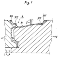
- the numerals 11, 12 denote a pair of mandrels which are rotatable (see the arrow) about the axis thereof.
- the numeral 2 denotes a rotary pressing device forming a pair with the mandrels 11, 12 is used when an intermediate raw material 3 of a vehicle wheel as will be described hereinafter is spinning molded.
- the numeral 3 denotes the intermediate raw material of a vehicle wheel which is sandwiched by the mandrels 11, 12. This vehicle wheel intermediate raw material 3 is spinning molded by sandwiching a raw material of a wheel (not shown) between the mandrels 11, 12 and drawn, while rotating, along the outer surfaces of the mandrels 11, 12 by the rotary pressing device 2.
- the thickness of a rim flange portion 311 and the thickness of a rim hump portion 312 in a rim portion 31 are formed greater than the finish dimension (shown by one dotted chain lines in Fig. 1). And after removed from the mandrels 11, 12, the vehicle wheel intermediate raw material 3 is heated and then the thickness of the rim flange portion 311 and the thickness of the rim hump portion 312 are finished to the finish dimension to obtain a vehicle wheel.
- the manufacturing process of a vehicle wheel of claim 1 is constituted in the manner as mentioned above, when the rim portion is molded through spinning molding, the thickness of only the peripheral edge portion of the rim portion is formed greater than the finish dimension and the cutting treatment after heat treatment is applied only to the peripheral edge portion. Accordingly, a portion requiring a cutting treatment in the succeeding processes becomes less.
- the manufacturing process of a vehicle wheel is employed, it does not take much time and labor for the cutting treatment after heat treatment which will be performed after the spinning molding, the vehicle wheel can be manufactured with ease and the yield of material is improved.
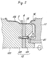
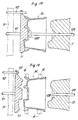
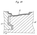
- the numeral 12 denotes a spinning molding mandrel (corresponding to the "molding die” of the present invention), which is rotatable about the axis 127 thereof.
- the numeral 126 denotes a reverse rim molding portion
- 13 denotes a drop center molding portion.
- this mandrel 12 is cut in the vertical direction with respect to the axis at the drop center molding portion 13 and split into an outer portion 121 and an inner portion 122.
- the numeral 4 denotes a molding auxiliary die which is removably sandwiched between the outer portion 121 and the inner portion 122 in the mandrel 12.
- the peripheral surface of this molding auxiliary die 4 is flushed with the molding portion of the drop center 13 of the mandrel 12 and acts as a drop center molding portion when spinning molding.
- the numeral 41 denotes a fixing bolt which is adapted to fix the molding auxiliary die 4 to the outer portion 121 and inner portion 122 in the mandrel 12.
- a vehicle wheel is molded in such constructed spinning molding die apparatus as mentioned above in the following manner.
- a vehicle wheel raw material (not shown) is placed on the mandrel 12 as such that the raw material is engaged with the outer surface of the mandrel 12 and clamped by the auxiliary mandrel 11. And while rotating this wheel raw material about the axis, it may simply be withdrawn by the rotary pressing device 4 in the direction as shown by the arrow. As a result, a vehicle wheel as shown in Fig. 2 is formed. In this case, the peripheral surface of the molding auxiliary die 4 forms a part of the drop center of the vehicle wheel W.
- the width of the rim of the vehicle wheel to be spinning molded is adjustable by changing the width of this molding auxiliary die.
- the spinning molding die apparatus of a vehicle wheel according to the present invention it is no more required to prepare several kinds of molding dies (mandrels) in order to spinning molding vehicle wheels which have different rim widths. As a consequence, the manufacturing cost of the molding die (mandrel) can be decreased and the maintenance of the molding die (mandrel) becomes comparatively easy.
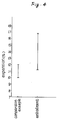
- a vehicle wheel raw material was cast from a spinning molding low Si material (Cu: 0.003 wt.%, Si: 4.6 wt. %, Mg. 0.36 wt.%, Fe: 0.12 wt.%, Mn: 0.004 wt.%, Ti: 0.10 wt.%, Sb: 0.078 wt.%, and remainder: Al), and this wheel raw material was spinning molded to manufacture a vehicle wheel. And the test results of the expansion in this vehicle wheel are shown in Figs. 3 and 4. The test was carried out in such a manner as that a dish-shaped (thickness: 10mm) test piece was made and the dish-shaped test piece was molded by a spinning machine.
- a vehicle wheel raw material was cast from a spinning molding 4C material (Cu: 0.006 wt.%, Si: 6.9 wt. %, Mg. 0.33 wt.%, Fe: 0.12 wt.%, Mn: 0.006 wt.%, Ti: 0.115 wt.%, Sb: 0.112 wt.%, and remainder: Al), and this wheel raw material was spinning molded to manufacture a vehicle wheel. And the test results of the expansion in this vehicle wheel are shown in Figs. 3 and 4. The test was carried out in the same procedure as the embodiment.
- the spinning molding material is constructed in the manner as mentioned above, if the spinning raw material is cast and this raw material is molded, the moldability is good because the expansion is excellent as shown in Figs. 3 and 4.
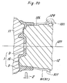
- the reference character D denotes a disk portion (corresponding to the "plate portion to be clamped” in some of the claims of the vehicle wheel raw material 1
- the numeral 5 denotes an outer side rim portion integrally formed on the outer peripheral edge portion of this disk portion D by forging or casting.
- the numeral 3 denotes a reversed side cylindrical rim raw material (corresponding to the "cylindrical raw material to be molded" of some of the claims) which is integrally formed on the reversed side peripheral edge portion of the disk portion D by forging or casting as in the case with the outer side rim portion 5.
- This reversed side cylindrical rim raw material 3 is made into a reversed side rim portion 31 the spinning molding, and the thickness A of the peripheral edge portion 32 is greater than the thickness B of the root and trunk portion.
- the numeral 316 denotes a twist which is formed on the outer wall surface at the connecting portion between the reversed side cylindrical raw material 3 and the disk portion D. This twist 316 extends like a groove over the peripheral surface of the reversed side cylindrical raw material 3.
- Such constructed vehicle wheel raw material 1 is placed on the mandrel 12.
- a gap S is formed between the reversed side cylindrical raw material 3 and the rim molding surface 123 of the mandrel 23.
- the angle ⁇ formed between the reversed side cylindrical raw material 3 and the rim molding surface 123 is preferably about 8 degrees.
- a front end portion 32 of the cylindrical rim raw material 3 is more projected (in the radial direction of the disk portion D) than the rim flange molding surface (corresponding to the "most projected portion" of some claims) 124 of the mandrel 12.
- the cylindrical raw material 3 is gradually deformed into the state as shown by the imaginary line (from the right-hand side to the left-hand side) to form the reversed side rim 31 and thus the vehicle wheel W.
- the numeral 11 denotes a pressing plate for clamp fixing the wheel raw material 1 to the mandrel 4.
- the spinning molding process is constituted in the manner as mentioned above, when the cylindrical raw material to be molded along the molding surface of the mandrel, the cylindrical raw material to be molded easily gets used to the molding surface along its projecting portion.
- the cylindrical raw material to be molded can be easily molded along the projecting molding surface (of the mandrel).
- the spinning molding process is constituted in the manner as mentioned above, when the cylindrical raw material to be molded is drawn along the projected part of the molding surface of the mandrel, there can be worked with a sufficient raw material.
- the connecting portion between the cylindrical raw material to be molded and the plate portion to be clamped can be made comparatively thin. Consequently, when such raw material as mentioned is cast, a decayed part is not easily occurred at the connecting portion. As a result, the strength of the spinning molded product can be maintained with ease.
- the vehicle wheel raw material 1 is placed on the mandrel 12.
- a gap S is formed between the reversed side cylindrical raw material 3 and the rim molding surface 123 of this mandrel 12 in such a manner as that the gap S is gradually dilated as it goes toward the front end portion of the reversed side cylindrical raw material 3.
- the angle ⁇ formed between reversed side cylindrical raw material 3 and the rim molding surface 123 is preferably about 5 to 30 degrees.
- the front end portion 32 of the cylindrical rim raw material 3 is larger in diameter in the radial direction of the disk portion D than the rim flange molding surface of the mandrel 12.
- this spinning molding process it is easy to spinning mold the cylindrical raw material to be molded into a predetermined shape of a vehicle wheel along molding mandrel.
- the reversed side cylindrical raw material 3 is formed into a reversed side rim portion 31 by spinning molding and is gradually dilated as it goes toward the front edge thereof. And the dilating angles ⁇ 1 ⁇ 2 and ⁇ 3 become steppingly larger as it goes toward the front edge.
- Such constructed vehicle wheel raw material 1 is placed on the mandrel 12.
- the dilating angles ⁇ 1, ⁇ 2 and ⁇ 3 of the rim molding surface 123 of this mandrel 12 are smaller than the dilating angles ⁇ 1 ⁇ 2 and ⁇ 3 of the reversed side cylindrical raw material 3.
- a gap S is formed which becomes gradually dilated as it goes toward the front edge.
- the cylindrical raw material to be molded can easily be spinning molded into a predetermined shape (for example, vehicle wheel) which is gradually steppingly dilated along the molding mandrel.
- the working performance of the spinning molding work is by far improved.
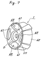
- the numeral 1 denotes a vehicle wheel raw material (corresponding to the "spinning molding cylindrical raw material” of some claims), which is integrally formed by forging.
- This vehicle wheel raw material 1 is molded into a vehicle wheel by spinning molding.
- Reference character D denotes a disk portion of the wheel raw material 1
- the numerals 61, 61, ⁇ denote spoke portions thereof.
- the spoke portions 61, 61, ⁇ radially extend from said disk portion D, and connected to the edge of a rim portion (corresponding to the "cylindrical body” of some claims.
- the numeral 111 denotes a axle hole of the disk portion D.
- the numerals 621, 621, ⁇ denote grooves which are formed on the inner peripheral surface of the rim portion 62 by warping the rim portion 62 outward.
- Each of the grooves 621 extends in the width direction (of the rim portion 62) from the connecting portion of the spoke portion 61.
- the numerals 611, 611 denote auxiliary grooves, which are formed on the rear sides of the spoke portions 61, 61, ⁇ . This auxiliary groove 611 is connected to the groove 621 of the rim portion 62, respectively.
- window portions 63, 63, ⁇ are not yet penetrated.
- the numeral 12 denotes a spinning molding mandrel which Is rotatable about the axis 127.
- the wheel raw material 1 is engaged with the outer periphery of this mandrel 12 which is clamped by a tail stock 11.
- gaps S, S, ⁇ generally corresponding to the depth of a groove portion 621 are created between the bottom surface of the groove portion 621 in the wheel raw material 1 and the molding surface of the mandrel 12.
- These gaps S, S, ⁇ extend in the width direction of the rim portion 62.
- a final product (shown by the solid line) can be obtained by cutting the vehicle wheel (see the imaginary line of the figure) which was subjected to the spinning molding. At this time, the window portions 63, 63, 63, ⁇ are penetrated.
- the spinning molding cylindrical raw material is constructed in the manner as described above, if this cylindrical raw material is fixed to the mandrel and drawn along the molding surface of the mandrel while partly pressing the outer peripheral surface of the cylindrical body in the cylindrical raw material with the pressing device by rotating the mandrel, the recess portion can be intermittently formed in the inner peripheral surface of the cylindrical body. As a consequence, the cylindrical body can be made light in weight.
- the recess portion can be formed by spinning molding.
- the recess portion can be formed in the inner peripheral surface of the root and truck portion (connecting portion between the rim portion of the vehicle wheel and the spoke portion ) of the cylindrical body which is spinning molded.
- the cylindrical body can be made light in weight.
- reference character A1 denotes a spinning molding apparatus
- numeral 125 denotes a rotational shaft of the spinning molding apparatus A1.
- This rotational shaft 125 is rotatable about the axis thereof.
- the numeral 12 denotes a mandrel which is removably engaged with the outer periphery of the rotational shaft 125.
- the peripheral surface of this mandrel 12 forms a die portion 126 for spinning molding a vehicle wheel W.
- the numeral 1 denotes a cast vehicle wheel raw material (corresponding to the "cast molding raw material to be molded" of the present invention), and the components thereof are Si; 5.0 ⁇ 9.0%, Mg; 0.15 ⁇ 0.4%, Ti; ⁇ 0.2%, Fe; ⁇ 0.3%, Al: remainder, or Si ⁇ 0.2%, Mg:2.5 ⁇ 5.5%, Ti ⁇ 0.2%, Mn ⁇ 0.6%, Al: remainder. It may cast from an AC4 material.
- This vehicle wheel raw material 1 is disposed on one side of the mandrel and clamped by the tail stock 11. Owing to the foregoing, in accordance with the rotation of the mandrel 12, the vehicle wheel raw material 1 is rotated in the same direction.
- This vehicle wheel raw material 1 is made by casting and comprises a disk portion D which is sandwiched between the mandrel 12 and the tail stock 11 and a rim raw material 11 (see the imaginary line of the figure). If the rim raw material 3 is drawn in the direction as shown by the arrow with the pressing spatula 2 while rotating the mandrel 12, the rim 31 is spinning molded.
- the numeral 8 denotes a burner (corresponding to the "heating means" of the present Invention) and is adapted to heat the rim raw material 3. This burner 8 is disposed on the pressing spatula 2 and moved in accordance with the movement of the pressing spatula 2. Owing to the foregoing, the working portion of the pressing spatula 2 can be partly heated.
- the raw material 3 is preferably heated to 230 ⁇ 400°C by a burner 8.
- the heating temperature is less than 230°C , moldability becomes poor and cracks are occurred, while if the heating temperature is 400°C or more, the disk portion (vehicle wheel raw material 4) D becomes too soft and is easily deformed.
- the temperature of the molding portion of the rim raw material 3 is measured by an infrared thermometer and the heating power of the gas burner 8 is adjusted in accordance with the feed back system. Upon start of the rotation of the mandrel 12, the burner 8 is ignited and the burner is extinguished upon stop of the rotation.
- the cast vehicle wheel raw material 1 is placed on the mandrel 12. And after clamped by the tail stock 11, the mandrel 12 is rotated at approximately 300RPM. At this time, the burner 8 is ignited simultaneously and starts heating the rim raw material 3. And when the temperature of the rim raw material has reached to a predetermined temperature (230 ⁇ 400°C), this rim raw material 3 is drawn in the direction as shown by the arrow by tile pressing spatula 2 to obtain the vehicle wheel W. After molding the vehicle wheel W, the mandrel 12 is stopped rotating. At this time, the gas burner 8 is extinguished simultaneously.
- the mandrel and/or the pressing spatula may be heated.
- the spinning molding apparatus is constructed in the manner as described above, the spinning molding can be carried out while maintaining the good ductility of the cast raw material to be molded.
- the cast raw material to be molded can be drawn along the mandrel with ease. Therefore, even when the cast raw material to be molded is rapidly machined into a complicated shape, unreasonableness is not occurred to the cast raw material to be molded. As a result, cracks are hardly created in such raw material.
- the raw material to be molded can be heated to 230 ⁇ 400°C by the heating means.
- the reason is that if the heating temperature is less than 230°C, the moldability becomes poor and cracks are created. On the other hand, if the heating temperature is 400°C or more, the raw material to be molded becomes too soft and the mandrel fixing portion in the raw material to be molded is easily deformed.
- the spinning molding apparatus according to the present invention if used, the cast raw material to be molded can be rapidly machined into a complicated shape with ease.
- the numeral 12 denotes a spinning molding mandrel
- 11 denotes a tail stock.
- the axis of the mandrel 12 is aligned with the axis of the tail stock 11.
- the numeral 119 denotes a shaft hole of the mandrel 12
- 126 denotes a first operation rod which is reciprocally movably disposed in the shaft hole 119.
- This first operation rod 125 is provided with an extruding plate 128 fixed to a front end thereof. This extruding plate 128 is used for removing the vehicle wheel W after molded.
- the numeral 91 denotes a second operation rod, which is reciprocally movably disposed on a substrate F of the spinning molding apparatus.
- this second operation rod 91 is fixed to the tail stock 11 and used to reciprocally move the tail stock 11 along the axis.
- the numeral 112 denotes a retaining hole (corresponding to the "retaining portion" of the present invention), which is formed on the edge of the tail stock 11.
- the numeral 92 denotes a retaining rod which is reciprocally movably disposed on the substrate F. By reciprocal movement of the retaining rod 92, it can be engaged with and disengaged from the retaining hole 112 of the tail stock 11.
- Fig. 14 the mandrel 12 is stopped in a suitable position.
- the tail stock 11 is now in its retreated position on the side of the substrate F by means of manipulation of the second operation rod 91.
- the retaining rod 92 is engaged in the retaining hole 112 of the tail stock 11.
- the numeral 1 denotes a vehicle wheel raw material (corresponding to the "raw material to be molded" of the invention) clamped by a chuck member C and disposed between the mandrel 12 and the tail stock 11.
- the chuck member C is adapted to clamp the vehicle wheel raw material 1.
- the second operation rod 91 is manipulated to extrude the tail stock 11 and the first operating rod 125 is manipulated to extrude the extruding plate 128 so that the wheel member 1 is held between the tail stock 11 and the extruding plate 128.
- the retaining rod is stretched and the retaining state in the retaining hole 112 is maintained.
- the second operation rod 91 is manipulated to retreat the tail stock 11 and the first operating rod 125 is manipulated to retreat the extruding plate 128 in order to release the vehicle wheel W from the tail stock 11 and extruding plate 128.
- the retaining rod 92 is also retreated in accordance with the retreatment of the tail stock 11 but its retaining state in the retaining hole 112 is maintained.
- the right position of the tail stock 11 with respect to the stopped state of the mandrel 12 is still maintained.
- the spinning apparatus of claim 19 is constructed in the manner as described in the above, if it is designed such that the corresponding position of the tail stock with respect to the stopped position of the mandrel is established beforehand and in such established position, the tail stock is separated from the mandrel and at the same time the tail stock is retained by the retaining rod, the tail stock can secure a right position with respect to this mandrel as long as the mandrel is being stopped in the above-mentioned state.
- the tail stock can be positioned with respect to the mandrel with ease.
- the mounting work of the raw material to be molded in the spinning molding can be extensively simplified compared with the prior art.
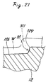
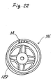
- the numeral 12 denotes a spinning molding mandrel which is rotatable about the axis 127 thereof.
- the numeral 1 denotes a wheel raw material (corresponding to the raw material to be molded" of the invention) and is clamped by the tail stock 11 in the state where the wheel raw material 1 is engaged with the outer periphery of the mandrel 12.
- This wheel raw material 1 comprises a disk portion D, a spoke portion 15, and a rim portion 3.
- the numeral 126 denotes a molding surface of the mandrel 12 which is formed on the peripheral surface of the mandrel 12. This molding surface 126 is adapted to mold the rim portion 31 of the vehicle wheel W.
- the numeral 129 denotes a rim flange molding portion which is formed on both edges of the mandrel 12.
- This rim flange molding portion 129 forms a plane generally vertical to the axis 127 of the mandrel 12.
- This rim flange molding portion 129 is provided with a displaying irregularity portion M formed thereon.
- This displaying irregularity portion M is formed in irregularity in accordance with the shapes of letters, marks, etc. They have shapes corresponding to, for example, size of a product, manufacturing date, etc.
- a suitable displaying means can be applied to the molded product while molding the raw material to be molded along the molding surface of the mandrel.
Claims (14)
- Procédé de fluotournage pour la fabrication d'une roue de véhicule, comportant les étapes de :
préparation d'une matière première (3) pour roue de véhicule, dans laquelle une matière première de jante est constituée en une seule pièce avec le bord périphérique d'un élément en disque,
formation d'une partie de jante (31) par fluotournage de ladite matière première de jante en faisant tourner ladite matière de roue autour de l'axe (127) dudit élément en disque, et ensuite de traitement thermique de la matière première fluotournée puis d'usinage par coupe de celle-ci,
caractérisé en ce qu'on façonne ladite partie de jante (31) pour que seuls ses deux bords aient une épaisseur supérieure à la dimension finie, lesdits deux bords de ladite partie de jante (31) étant ainsi une partie de jante en saillie (312) et une partie de jante en collerette (311). - Procédé de fluotournage selon la revendication 1, caractérisé en ce qu'on fixe sur la surface extérieure (123) d'un mandrin (12) une matière première cylindrique de fluotournage (1) présentant une partie en rainure (621) formée sur la surface latérale intérieure d'un corps cylindrique suivant la direction de la largeur de ce corps, on met en rotation ladite matière première cylindrique (1) en faisant tourner ledit mandrin (12) autour de son axe (125) et on étire ledit corps cylindrique le long de la surface de façonnage (123) dudit mandrin (12) tandis que l'on presse partiellement la surface périphérique dudit corps cylindrique avec un dispositif presseur (2).
- Procédé de fluotournage selon la revendication 1 ou la revendication 2, caractérisé en ce qu'on forme la matière première cylindrique à façonner (3) en une seule pièce avec les bords périphériques (311,312) d'une partie de blocage en plaque (D), ladite matière première cylindrique (3) étant en liaison par fluotournage avec la surface latérale extérieure du mandrin de fluotournage (12) suivant une forme prédéterminée.
- Procédé de fluotournage selon au moins l'une des revendications 1 à 3, caractérisé en ce qu'on forme une partie périphérique déviée semblable à une rainure (316) sur la surface de paroi extérieure d'une zone assurant essentiellement la liaison entre ladite matière première cylindrique à façonner (3) et ladite partie de blocage en plaque (D).
- Procédé de fluotournage selon la revendication 4, caractérisé en ce qu'on forme un intervalle (5) entre ladite matière première cylindrique à façonner (3) et ledit mandrin de fluotournage (12) quand la matière première est montée sur ledit mandrin de fluotournage (12), ledit intervalle (5) étant formé de manière que sa largeur devienne progressivement plus grande en allant vers le bord périphérique (32) de la matière première.
- Procédé de fluotournage selon la revendication 5, dans lequel l'angle (ϑ) forme entre ladite matière première cylindrique à façonner (3) et la surface de façonnage (123) dudit mandrin de fluotournage (12) est compris entre 5 et 30 degrés environ.
- Procédé de fluotournage selon au moins l'une des revendications 1 à 6, caractérisé en ce qu'on forme une partie périphérique (32) de ladite matière première cylindrique (3) située sur la zone en saillie la plus élevée de la surface de façonnage (123) dudit mandrin de fluotournage (12) quand ladite matière première cylindrique (3) est montée sur ledit mandrin de fluotournage (12).
- Procédé de fluotournage selon au moins l'une des revendications 1 à 7 et utilisant un appareil de fluotournage, caractérisé par une matrice de fluotournage (3) sur la périphérie de laquelle on doit placer une matière première de roue (3) et par un dispositif presseur tournant (2) constitué séparément et adapté à étirer ladite matière première de roue (3) le long de ladite matrice de fluotournage (12) pendant que l'on fait tourner ladite matière première de roue (3) conjointement avec ladite matrice de fluotournage (12), et caractérisé en outre en ce qu'une zone de façonnage centrale abaissée (13) de ladite matrice de fluotournage (12) est coupée en direction verticale perpendiculairement à son axe (127), une matrice de fluotournage auxiliaire (4) étant disposée dans l'intervalle formé par le plan de coupe.
- Procédé de fluotournage selon la revendication 8, comportant : un mandrin en tant que matrice de fluotournage (12), sur lequel on place une matière première moulée à façonner, des moyens de chauffage (8) pour chauffer ladite matière première moulée à façonner (1) qui est mise en rotation suivant la rotation dudit mandrin et un dispositif presseur (2) à spatule de pression pour presser ladite matière première moulée à façonner, de manière que ladite matière moulée à façonner soit en même temps étirée le long dudit mandrin.
- Procédé de fluotournage selon les revendications 8 et 9, caractérisé en ce les moyens de chauffage (8) assurent le chauffage de la matière première moulée à façonner à une température de 230 à 400° C environ.
- Procédé de fluotournage selon au moins l'une des revendications 8 à 10, comportant la disposition du mandrin de fluotournage (12) et d'une partie arrière (11) sur un bâti de manière que les axes (125) dudit mandrin et de la partie arrière soient alignés, ledit mandrin et la partie arrière étant mobiles en va-et-vient suivant lesdits axes (125) et pouvant tourner autour desdits axes, l'étirage de ladite matière première à façonner, bloquée par ledit mandrin et ladite partie arrière, par le dispositif presseur (2) le long d'une surface de façonnage dudit mandrin suivant une forme prédéterminée tandis que l'on fait tourner ledit mandrin, et une tige de maintien (92) mobile en va-et-vient et disposée sur ledit bâti pour se déplacer dans la direction de l'axe de la partie arrière, une partie de retenue étant montée sur ladite partie arrière de manière que ladite partie arrière puisse être maintenue par ladite partie de retenue.
- Procédé de fluotournage selon au moins l'une des revendications 8 à 11, caractérisé en ce qu'une zone présentant des éléments non réguliers est formée sur ladite surface de façonnage (126) dudit mandrin (12).
- Procédé de fluotournage selon au moins l'une des revendications 1 à 7, en utilisant une matière à façonner contenant 3 à 6 pour cent en poids de Si et 0,2 à 0,5 pour cent en poids de Mg.
- Procédé de fluotournage selon la revendication 13, caractérisé en ce qu'on utilise les composants suivants :
Si : 5,0 à 9,0 % ; Mg : 0,15 à 0,4 % ; Ti : 0,2 % ; Fe : 0,3 % et le reste en Al, ou
Si : 0,2 % ; Mg : 2,5 à 5,5 % ; Ti : 0,2 % ; Mn : 0,6 % et le reste en Al.
Priority Applications (1)
| Application Number | Priority Date | Filing Date | Title |
|---|---|---|---|
| AT89119657T ATE101066T1 (de) | 1988-10-24 | 1989-10-23 | Verfahren zum fliessdruecken, fliessdrueckvorrichtung, fliessdruecken von rohmaterial, fliessdrueckverfahren und vorrichtung fuer ein fahrzeugrad. |
Applications Claiming Priority (12)
| Application Number | Priority Date | Filing Date | Title |
|---|---|---|---|
| JP26856088A JPH0716747B2 (ja) | 1988-10-24 | 1988-10-24 | スピニング成形用素材 |
| JP268560/88 | 1988-10-24 | ||
| JP63268559A JPH0763794B2 (ja) | 1988-10-24 | 1988-10-24 | スピニング成形方法 |
| JP268559/88 | 1988-10-24 | ||
| JP1093339A JP2775288B2 (ja) | 1989-04-13 | 1989-04-13 | スピニング成形用筒状素材および筒体のスピニング成形方法 |
| JP93339/89 | 1989-04-13 | ||
| JP220068/89 | 1989-08-26 | ||
| JP22006789A JP2745028B2 (ja) | 1989-08-26 | 1989-08-26 | スピニング成形装置および車両用ホイールのスピニング成形装置 |
| JP220069/89 | 1989-08-26 | ||
| JP22006989A JP2704233B2 (ja) | 1989-08-26 | 1989-08-26 | スピニング成形装置 |
| JP220067/89 | 1989-08-26 | ||
| JP22006889A JP2704232B2 (ja) | 1989-08-26 | 1989-08-26 | スピニング成形装置 |
Publications (3)
| Publication Number | Publication Date |
|---|---|
| EP0366049A2 EP0366049A2 (fr) | 1990-05-02 |
| EP0366049A3 EP0366049A3 (fr) | 1991-07-17 |
| EP0366049B1 true EP0366049B1 (fr) | 1994-02-02 |
Family
ID=27551896
Family Applications (1)
| Application Number | Title | Priority Date | Filing Date |
|---|---|---|---|
| EP89119657A Expired - Lifetime EP0366049B1 (fr) | 1988-10-24 | 1989-10-23 | Procédé de fluotournage, appareil de fluotournage, fluotournage de matière première, procédé et appareil de fluotournage d'une roue de véhicule |
Country Status (6)
| Country | Link |
|---|---|
| US (1) | US5092040A (fr) |
| EP (1) | EP0366049B1 (fr) |
| KR (2) | KR930010312B1 (fr) |
| AU (3) | AU639674B2 (fr) |
| CA (1) | CA2001372A1 (fr) |
| DE (2) | DE68912874D1 (fr) |
Cited By (1)
| Publication number | Priority date | Publication date | Assignee | Title |
|---|---|---|---|---|
| DE4442465A1 (de) * | 1994-11-25 | 1996-05-30 | Asahi Tec Corp | Verfahren zum Herstellen eines Fahrzeugrades im Fließdrückverfahren |
Families Citing this family (30)
| Publication number | Priority date | Publication date | Assignee | Title |
|---|---|---|---|---|
| WO1991006384A1 (fr) * | 1989-10-30 | 1991-05-16 | Asahi Malleable Iron Co., Ltd. | Installation de moulage en rotation |
| FR2727336B1 (fr) * | 1994-11-29 | 1997-01-31 | Asahi Tec Corp | Procede de fluotournage d'une roue de vehicule |
| EP0743112A1 (fr) * | 1995-05-17 | 1996-11-20 | Metal Forming Machines, Inc. | Appareil et méthode de fabrication d'une roue de véhicule |
| IT1279738B1 (it) * | 1995-09-29 | 1997-12-16 | Reynolds Wheels Spa | Procedimento di formatura di cerchi per pneumatici in lega metallica |
| DE19615675C2 (de) * | 1996-04-19 | 1998-12-17 | Leifeld Gmbh & Co | Verfahren zum Herstellen eines Fahrzeugrades |
| US6536111B1 (en) | 1996-07-24 | 2003-03-25 | Hayes Lemmerz International, Inc. | Process for spin forming a vehicle wheel |
| US6539765B2 (en) | 2001-03-28 | 2003-04-01 | Gary Gates | Rotary forging and quenching apparatus and method |
| DE10141510A1 (de) * | 2001-08-24 | 2003-03-13 | Audi Ag | Verfahren zum Herstellen von Leichtmetall-Felgen |
| JP2003127030A (ja) * | 2001-10-22 | 2003-05-08 | Enkei Kk | アルミニウム合金製ホイールの製造方法 |
| US6719173B2 (en) * | 2002-03-25 | 2004-04-13 | Owens-Brockway Plastic Products Inc. | Multilayer container package for dispensing a liquid product |
| US20070144007A1 (en) * | 2003-06-09 | 2007-06-28 | Smyth Larry C | Method for marking a vehicle wheel for subsequent identification and tracking |
| KR101153083B1 (ko) * | 2003-08-11 | 2012-06-04 | 와시 고산 가부시키가이샤 | 휠의 제조 방법과 그 휠 |
| US7228629B2 (en) | 2003-11-10 | 2007-06-12 | Beyer Michael J | Method of spin forming an automotive wheel rim |
| WO2005065049A2 (fr) * | 2004-01-07 | 2005-07-21 | Wheels India Limited | Roue de construction monobloc et procede de fabrication |
| ATE501799T1 (de) * | 2004-01-07 | 2011-04-15 | Wheels India | Einteilig ausgeführte räder und herstellungsverfahren dafür |
| US20070186417A1 (en) * | 2004-03-03 | 2007-08-16 | Smyth Larry C | Method for electronically identifying a coded part |
| NL1026796C2 (nl) * | 2004-08-06 | 2006-02-07 | Fontijne Grotnes B V | Werkwijze en inrichting voor het door middel van koude vervorming vervaardigen van een velgring. |
| US20100031508A1 (en) * | 2006-04-07 | 2010-02-11 | Peio Todorov Stoyanov | One-piece wheel produced by casting a wheel hub and spin-forming rims |
| US8852752B2 (en) * | 2011-01-11 | 2014-10-07 | Metal Forming & Coining Corporation | Flow formed drum with a retention ring and a substantially burr free tooth profile |
| KR101420611B1 (ko) * | 2012-04-13 | 2014-07-21 | 주식회사 대유신소재 | 플로우 포밍 성형기 |
| KR101370082B1 (ko) * | 2012-04-13 | 2014-03-06 | 주식회사 대유신소재 | 플로우 포밍 성형기 |
| CN103831593B (zh) * | 2014-03-20 | 2016-04-06 | 浙江亿利达风机股份有限公司 | 空调风机端圈的成型方法 |
| CN104191906B (zh) * | 2014-08-20 | 2016-05-04 | 上海兴浦旋压车轮有限公司 | 一体式型钢无焊缝车轮及其成型方法 |
| CN104191900B (zh) * | 2014-08-20 | 2016-07-06 | 上海兴浦旋压车轮有限公司 | 一体式板材无焊缝车轮及其成型方法 |
| CN104551544B (zh) * | 2014-11-14 | 2017-09-26 | 保定市立中车轮制造有限公司 | 提高铝合金车轮毂旋压成型成品率的制造方法 |
| CN106734669A (zh) * | 2016-12-26 | 2017-05-31 | 安庆迪力机械铸造有限公司 | 一种叉车轮毂用旋压扩口装置 |
| CN106825272A (zh) * | 2016-12-26 | 2017-06-13 | 安庆迪力机械铸造有限公司 | 一种叉车轮毂扩口装置 |
| CN106424406B (zh) * | 2016-12-26 | 2018-08-17 | 安庆迪力机械铸造有限公司 | 一种加热旋压扩口装置 |
| GB2563068B (en) * | 2017-06-02 | 2022-10-12 | Gkn Aerospace Services Ltd | Friction forming |
| CN113369362B (zh) * | 2021-06-07 | 2022-08-30 | 四川航天长征装备制造有限公司 | 一种航天用套罩成形方法 |
Family Cites Families (8)
| Publication number | Priority date | Publication date | Assignee | Title |
|---|---|---|---|---|
| DE1068654B (fr) * | 1959-11-12 | |||
| US1528734A (en) * | 1921-12-21 | 1925-03-03 | Robertshaw Mfg Company | Burner control |
| US2075294A (en) * | 1934-03-26 | 1937-03-30 | Kelsey Hayes Wheel Co | Method of forming vehicle wheels |
| DE1908465C3 (de) * | 1969-02-20 | 1973-10-04 | Fa. Otto Fuchs, 5892 Meinerzhagen | Verfahren zur Herstellung eines emstuckigen Leichtmetall Speichen rades |
| US4528734A (en) * | 1982-07-08 | 1985-07-16 | Ni Industries, Inc. | Method of spin forging a vehicle wheel |
| WO1986000549A1 (fr) * | 1984-07-05 | 1986-01-30 | Washi Kosan Co., Ltd. | Procede de production de jantes en alliage leger |
| JPS61115640A (ja) * | 1984-11-07 | 1986-06-03 | Washi Kosan Kk | 軽合金製ホイ−ルの製造方法 |
| JPS61115641A (ja) * | 1984-11-12 | 1986-06-03 | Washi Kosan Kk | 軽合金製ホイ−ルの製造方法 |
-
1989
- 1989-10-20 AU AU43606/89A patent/AU639674B2/en not_active Ceased
- 1989-10-23 EP EP89119657A patent/EP0366049B1/fr not_active Expired - Lifetime
- 1989-10-23 DE DE89119657A patent/DE68912874D1/de not_active Expired - Fee Related
- 1989-10-23 DE DE68912874T patent/DE68912874T4/de not_active Expired - Lifetime
- 1989-10-24 CA CA002001372A patent/CA2001372A1/fr not_active Abandoned
- 1989-10-24 US US07/426,953 patent/US5092040A/en not_active Expired - Lifetime
- 1989-10-24 KR KR1019890015281A patent/KR930010312B1/ko not_active IP Right Cessation
-
1992
- 1992-04-10 KR KR1019920005971A patent/KR930010314B1/ko not_active IP Right Cessation
- 1992-05-07 AU AU16096/92A patent/AU651197B2/en not_active Ceased
-
1993
- 1993-05-26 AU AU39824/93A patent/AU657411B2/en not_active Ceased
Cited By (1)
| Publication number | Priority date | Publication date | Assignee | Title |
|---|---|---|---|---|
| DE4442465A1 (de) * | 1994-11-25 | 1996-05-30 | Asahi Tec Corp | Verfahren zum Herstellen eines Fahrzeugrades im Fließdrückverfahren |
Also Published As
| Publication number | Publication date |
|---|---|
| US5092040A (en) | 1992-03-03 |
| DE68912874T4 (de) | 1995-08-31 |
| AU4360689A (en) | 1990-04-26 |
| DE68912874D1 (de) | 1994-03-17 |
| AU657411B2 (en) | 1995-03-09 |
| KR930010312B1 (ko) | 1993-10-16 |
| KR930010314B1 (ko) | 1993-10-16 |
| AU639674B2 (en) | 1993-08-05 |
| DE68912874T2 (de) | 1994-08-25 |
| EP0366049A2 (fr) | 1990-05-02 |
| AU1609692A (en) | 1992-07-09 |
| AU3982493A (en) | 1993-08-05 |
| KR900006039A (ko) | 1990-05-07 |
| AU651197B2 (en) | 1994-07-14 |
| EP0366049A3 (fr) | 1991-07-17 |
| CA2001372A1 (fr) | 1990-04-24 |
Similar Documents
| Publication | Publication Date | Title |
|---|---|---|
| EP0366049B1 (fr) | Procédé de fluotournage, appareil de fluotournage, fluotournage de matière première, procédé et appareil de fluotournage d'une roue de véhicule | |
| US6539765B2 (en) | Rotary forging and quenching apparatus and method | |
| JP2538183B2 (ja) | 車両の一体車輪を製作する方法 | |
| CA1053989A (fr) | Methode de tournage entre galets d'ebauches metalliques en forme de gobelet, et montage a galets correspondant | |
| US4606206A (en) | Method and apparatus for edge preparation of spinning blanks | |
| US6757976B2 (en) | Method for manufacturing alloy wheel for automobile | |
| US3822458A (en) | Method of making wheels | |
| EP0984837B1 (fr) | Procede et dispositif de production d'une roue de vehicule d'une seule piece | |
| US4208900A (en) | Axle spindle forming apparatus | |
| HU176781B (en) | Method for producing one-section wheel-discs by die forging and metal spinning | |
| US4708749A (en) | Method of calibrating vehicle wheels to a finished size | |
| US6298702B1 (en) | Method for making seamless wheel rims | |
| JP3390838B2 (ja) | 自動車用ホイールの成形方法 | |
| JP2700308B2 (ja) | 内歯車の製造法 | |
| JPH09295091A (ja) | 回転対称形状部品の製造方法 | |
| CA1080520A (fr) | Appareil et mode de faconnage de fusees d'essieu | |
| HU184429B (en) | Aluminium wheel particularly vehicle one furthermore method and apparatus for producing same | |
| CA1291866C (fr) | Methode de production de roues en alliage leger | |
| JPS63134B2 (fr) | ||
| US4687524A (en) | Method of forming to a finished size vehicle wheels made of a heat-treatable aluminum alloy | |
| US6571590B1 (en) | Method for producing a rim for a pneumatic tire | |
| JPH0356819B2 (fr) | ||
| JPH0154138B2 (fr) | ||
| JPH0471743A (ja) | 自動車用ホイールの製造方法 | |
| KR930010315B1 (ko) | 스피닝 성형소재 |
Legal Events
| Date | Code | Title | Description |
|---|---|---|---|
| PUAI | Public reference made under article 153(3) epc to a published international application that has entered the european phase |
Free format text: ORIGINAL CODE: 0009012 |
|
| AK | Designated contracting states |
Kind code of ref document: A2 Designated state(s): AT BE CH DE FR GB IT LI LU NL SE |
|
| PUAL | Search report despatched |
Free format text: ORIGINAL CODE: 0009013 |
|
| AK | Designated contracting states |
Kind code of ref document: A3 Designated state(s): AT BE CH DE FR GB IT LI LU NL SE |
|
| 17P | Request for examination filed |
Effective date: 19920110 |
|
| 17Q | First examination report despatched |
Effective date: 19920831 |
|
| GRAA | (expected) grant |
Free format text: ORIGINAL CODE: 0009210 |
|
| RAP1 | Party data changed (applicant data changed or rights of an application transferred) |
Owner name: ASAHI TEC CORPORATION |
|
| AK | Designated contracting states |
Kind code of ref document: B1 Designated state(s): AT BE CH DE FR GB IT LI LU NL SE |
|
| PG25 | Lapsed in a contracting state [announced via postgrant information from national office to epo] |
Ref country code: SE Effective date: 19940202 Ref country code: NL Effective date: 19940202 Ref country code: LI Effective date: 19940202 Ref country code: CH Effective date: 19940202 Ref country code: BE Effective date: 19940202 Ref country code: AT Effective date: 19940202 |
|
| REF | Corresponds to: |
Ref document number: 101066 Country of ref document: AT Date of ref document: 19940215 Kind code of ref document: T |
|
| REF | Corresponds to: |
Ref document number: 68912874 Country of ref document: DE Date of ref document: 19940317 |
|
| ET | Fr: translation filed | ||
| ITF | It: translation for a ep patent filed |
Owner name: SOCIETA' ITALIANA BREVETTI S.P.A. |
|
| REG | Reference to a national code |
Ref country code: CH Ref legal event code: PL |
|
| NLV1 | Nl: lapsed or annulled due to failure to fulfill the requirements of art. 29p and 29m of the patents act | ||
| ITTA | It: last paid annual fee | ||
| PG25 | Lapsed in a contracting state [announced via postgrant information from national office to epo] |
Ref country code: LU Free format text: LAPSE BECAUSE OF NON-PAYMENT OF DUE FEES Effective date: 19941031 |
|
| PLBE | No opposition filed within time limit |
Free format text: ORIGINAL CODE: 0009261 |
|
| STAA | Information on the status of an ep patent application or granted ep patent |
Free format text: STATUS: NO OPPOSITION FILED WITHIN TIME LIMIT |
|
| 26N | No opposition filed | ||
| PGFP | Annual fee paid to national office [announced via postgrant information from national office to epo] |
Ref country code: GB Payment date: 19971023 Year of fee payment: 9 |
|
| PGFP | Annual fee paid to national office [announced via postgrant information from national office to epo] |
Ref country code: FR Payment date: 19971029 Year of fee payment: 9 |
|
| PGFP | Annual fee paid to national office [announced via postgrant information from national office to epo] |
Ref country code: DE Payment date: 19971030 Year of fee payment: 9 |
|
| PG25 | Lapsed in a contracting state [announced via postgrant information from national office to epo] |
Ref country code: GB Free format text: LAPSE BECAUSE OF NON-PAYMENT OF DUE FEES Effective date: 19981023 |
|
| GBPC | Gb: european patent ceased through non-payment of renewal fee |
Effective date: 19981023 |
|
| PG25 | Lapsed in a contracting state [announced via postgrant information from national office to epo] |
Ref country code: FR Free format text: LAPSE BECAUSE OF NON-PAYMENT OF DUE FEES Effective date: 19990630 |
|
| REG | Reference to a national code |
Ref country code: FR Ref legal event code: ST |
|
| PG25 | Lapsed in a contracting state [announced via postgrant information from national office to epo] |
Ref country code: DE Free format text: LAPSE BECAUSE OF NON-PAYMENT OF DUE FEES Effective date: 19990803 |
|
| PG25 | Lapsed in a contracting state [announced via postgrant information from national office to epo] |
Ref country code: IT Free format text: LAPSE BECAUSE OF NON-PAYMENT OF DUE FEES;WARNING: LAPSES OF ITALIAN PATENTS WITH EFFECTIVE DATE BEFORE 2007 MAY HAVE OCCURRED AT ANY TIME BEFORE 2007. THE CORRECT EFFECTIVE DATE MAY BE DIFFERENT FROM THE ONE RECORDED. Effective date: 20051023 |