EP0365847B1 - Dispositif ralentisseur de sortie pour une machine pour imprimer des feuilles - Google Patents
Dispositif ralentisseur de sortie pour une machine pour imprimer des feuilles Download PDFInfo
- Publication number
- EP0365847B1 EP0365847B1 EP89117718A EP89117718A EP0365847B1 EP 0365847 B1 EP0365847 B1 EP 0365847B1 EP 89117718 A EP89117718 A EP 89117718A EP 89117718 A EP89117718 A EP 89117718A EP 0365847 B1 EP0365847 B1 EP 0365847B1
- Authority
- EP
- European Patent Office
- Prior art keywords
- sheet
- chain
- suction
- slide
- suction device
- Prior art date
- Legal status (The legal status is an assumption and is not a legal conclusion. Google has not performed a legal analysis and makes no representation as to the accuracy of the status listed.)
- Expired - Lifetime
Links
Images


Classifications
-
- B—PERFORMING OPERATIONS; TRANSPORTING
- B65—CONVEYING; PACKING; STORING; HANDLING THIN OR FILAMENTARY MATERIAL
- B65H—HANDLING THIN OR FILAMENTARY MATERIAL, e.g. SHEETS, WEBS, CABLES
- B65H29/00—Delivering or advancing articles from machines; Advancing articles to or into piles
- B65H29/68—Reducing the speed of articles as they advance
- B65H29/683—Slowing-down from chain delivery
-
- B—PERFORMING OPERATIONS; TRANSPORTING
- B65—CONVEYING; PACKING; STORING; HANDLING THIN OR FILAMENTARY MATERIAL
- B65H—HANDLING THIN OR FILAMENTARY MATERIAL, e.g. SHEETS, WEBS, CABLES
- B65H29/00—Delivering or advancing articles from machines; Advancing articles to or into piles
- B65H29/24—Delivering or advancing articles from machines; Advancing articles to or into piles by air blast or suction apparatus
-
- B—PERFORMING OPERATIONS; TRANSPORTING
- B65—CONVEYING; PACKING; STORING; HANDLING THIN OR FILAMENTARY MATERIAL
- B65H—HANDLING THIN OR FILAMENTARY MATERIAL, e.g. SHEETS, WEBS, CABLES
- B65H2406/00—Means using fluid
- B65H2406/30—Suction means
-
- B—PERFORMING OPERATIONS; TRANSPORTING
- B65—CONVEYING; PACKING; STORING; HANDLING THIN OR FILAMENTARY MATERIAL
- B65H—HANDLING THIN OR FILAMENTARY MATERIAL, e.g. SHEETS, WEBS, CABLES
- B65H2801/00—Application field
- B65H2801/03—Image reproduction devices
- B65H2801/21—Industrial-size printers, e.g. rotary printing press
Definitions
- the invention relates to a delivery sheet brake for a sheet printing machine, which has the features according to the preamble of claim 1.
- the suction member is formed in this known embodiment by a suction device, the support of which is supported by a lever guide, one lever of which is connected to an eccentric of a uniformly rotating first drive element, which brings about the lifting and lowering movements of the suction device, and the other lever of which second drive member is coupled, which triggers the horizontal movements of the vacuum cleaner.
- This second drive element consists of a cam disk, against which a roller is held, which is mounted on a toothed segment which engages in a gearwheel fastened to the lever on the same shaft.
- Such a drive for the delivery sheet brake enables the suction cup to be lifted against the rear edge of the sheet that runs approximately horizontally into the delivery by the one drive member and at the same time the horizontal movement of the suction device is accelerated to about the sheet speed by the other drive member from a starting position as short as possible Ways.
- the suction device is lowered by the first drive element against the delivery stack and at the same time as long as possible decelerated by the other drive member before the suction device releases the sheet in the release position and returns to the starting position at a relatively high speed, whereby also interact both drive links.
- Both drive links are connected to the drive of the conveying means in the boom via gear wheels and drive chains.
- the publication contains no information about the adjustment of the suction position and the suction drive in the event of a change in the format of the sheets to be printed. Since the drive means for the suction device are positively connected to it and are consequently arranged on the slide for the format adjustment, the delivery sheet brake must be adjusted if the format of the sheet to be printed is changed. This is time-consuming and leads to greasing and inaccurate paper feed, especially at high printing speeds.
- the drives of the suction device of the delivery sheet brake known from this publication are very complex.
- the US-PS 2 130 841 shows a delivery sheet brake, in which the vertical and horizontal movements of a suction cup are achieved by separate drive means. This publication also does not take into account the problems caused by changes in the format of the sheets to be printed.
- the suction element of the delivery sheet brake is driven phase-neutral directly by the drive of the printing press.
- This phase-neutral drive is not interrupted if the format of the sheets to be printed is changed, the change in length of the drive chain between the drive element of the suction element and the machine being compensated for by the chain store.
- the direct coupling of the drive element for the suction element to the drive of the printing machine has the effect that the speed of the suction element, which is matched to the sheet speed, is maintained, irrespective of the respective machine speed. With a format adjustment, the phase position of the suction element relative to the rear edge of the sheet is also retained.
- Format adjustments and changes in the machine running speed can be carried out while the machine is running without the phase position of the suction element in the delivery sheet brake being influenced, which is a significant advantage of the drive of the suction member of the delivery sheet brake designed using the inventive features, which can be seen directly from the machine.
- a cam forms the drive element for the suction member, a roller being held against this cam under spring tension, the movements of which are transmitted to the suction member by means of a transmission gear which is movably mounted on the slide for format adjustment about a transverse axis.
- This transmission gear is designed in an advantageous constructive design of the features of the invention as a lever gear, which has four joints, of which two joints are fixed on the adjustable carriage for format adjustment and spherical bearings for the form one end of two levers, the other ends of which are movably connected to one another by a further lever in the other two joints, one of the first two levers having a joint fixed on the slide rigid with a support bearing of the roller on the cam disc and the other of these two Lever is rigidly connected to a shaft mounted on the slide and extending with its axis transverse to the transport direction of the sheet and carrying the suction element.
- Such a four-bar linkage from levers connected to one another in an articulated manner is inexpensive to manufacture, reliable in operation and enables relatively large transmission ratios with a relatively small construction volume.
- Preferred training features for the design of the chain store contain claims 3 to 6.
- the suction element can either be formed by a suction disc or by a lifting suction device, wherein a lifting suction device does not require its own drive means for the lifting movement.
- a possible lifting movement of the suction device can, if necessary, be brought about directly by the negative pressure in the suction device and can be controlled by applying the sheet to the suction device.
- the drawing shows a schematic representation of the arrangement of the features of the invention and their configuration.
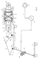
- the sheet 1 arriving from the printing press is transported by a conveyor chain 2 over the delivery stack 3.
- Grippers 4 on the conveyor chain guided over deflections 5 and 6 grasp the sheet 1 on its front edge.
- the sheet 1 is guided approximately horizontally into the delivery.
- a suction member 7 engages the rear edge of the sheet 1, which is released at the same time or with little overlap by the grippers 4 of the conveyor chain 2, so that the sheet 1 is lowered onto the sheet stack and thereby by the movement the suction member 7 is delayed and finally placed gently on the sheet stack 3.
- This delay of the sheet should take place as long as possible, so that the suction member must be accelerated to the sheet speed in the shortest possible way so that it can take over the sheet without relative speed to the sheet and return to the starting position at low speed when it takes the sheet released for storage on the delivery pile.
- This movement is achieved by a drive member from a cam 8, which is rotatably mounted about a horizontal shaft in the carriage 9, which carries all parts for the format adjustment, and whose horizontal adjustment option is illustrated by the circles symbolically indicated on the underside of the carriage 9.
- the suction member is one with its axis parallel to the axis of rotation 10 arranged shaft 11 movable.
- a roller 12 is pressed against the circumference of the cam plate 8 in a manner known per se by spring force, for example by a tension spring 35 according to FIG. 2, which roller is mounted on the free end of a short lever 13 of a four-link mechanism consisting of several levers, which forms the transmission mechanism .
- Another lever 14 is fixed to the shaft 11. Its free end is connected in the joint 17a to one end of a lever 15, the other end of which is connected in the joint 17b to a lever 16 which has a rigid connection with the lever 13 supporting the bearing of the roller 12 or is integral therewith is trained.
- the two levers 13 and 16 have a common joint 17c, which is arranged on the carriage 9.
- the lever 14 is also mounted on the slide 9 via the shaft 11 in the joint 17d.
- a sprocket 18 is fixedly connected, which is driven by a drive chain 19 directly from a sprocket 20 of the machine drive.
- the drive chain 19 passes through a chain store 21, which holds both chain runs 19a and 19b under uniform tension.
- the sprocket 18 on the cam 8 can be adjusted at a distance from the sprocket 20, but the phase position between the two sprockets 18 and 20 is retained. This enables format adjustments and speed changes of the machine without influencing the adjusted position and movement of the suction element 7 of the delivery sheet brake.
- both chain runs 19a and 19b are guided over a plurality of deflection rollers 22 and 23, the chain runs 19a and 19b alternately partially wrapping around the rollers 22 and 23 respectively assigned to them.
- the rollers 22 supporting the one chain center 19a are supported on a common carrier 24 and the rollers 23 supporting the other chain center 19b are supported on a common carrier 25, both of which are pressed apart by coil springs 26 and 27 and by at least one scissor cross 33 made of two in the Middle 34 hinged tabs, one end of which in one carrier and the opposite ends in the other carrier are slidably guided parallel to one another, the parallel position of the guides being maintained relative to one another.
- the two are arranged at the ends of these beams
- Coil springs 26 and 27 push the carriers 24 and 25 apart and thus bring about constant tension in the conveyor chain 19, changes in the distance between the two sprockets 18 and 20 are thereby compensated for without phase shift.
- FIG. 2 shows a suction element 7 comprising at least one suction device 28 and a housing 29, which guides the suction device 28 in a longitudinally movable manner, so that the suction device 28 can extend from the housing and be retracted into the housing.
- This movement takes place through the negative pressure in the line to the suction device 28 and is controlled by the contact of the sheet 1 with the suction device 28.
- the suction device 28 is moved out of the housing, this movement being able to take place, for example, by centrifugal force or by the negative pressure in the suction line connected to a vacuum pump 31.
- the suction device As soon as the suction device has grasped the rear edge of the sheet 1 and the suction opening of the suction device 28 is closed by the sheet 1, the negative pressure in the supply line to the suction device pulls it into the housing. This lowering movement of the suction cup makes the path of the deceleration phase lengthened because the suction opening of the suction cup moves on an elliptical path.
- the suction member 7 After the sheet 1 has been released by the suction device 28, the suction member 7 returns to the starting position and is then accelerated again to take over the next sheet into the take-over position.
- the sheet can be sucked in and released in a known manner, for example by a rotary valve 32 driven by the machine.
- a suction disk 30 is provided, which is fastened on the shaft 11 instead of the housing 29 of a suction device 28.
- a suction disc 30 is also moved by a transmission gear consisting of a plurality of levers 13, 14, 17, and 17 d, which are connected to one another by joints 17a, 17b, 17c and 17d, via a roller 12 by a rotatingly driven cam 8.
- an electric drive motor for the suction disk can also be provided with a control by a rotation angle sensor which is arranged directly on the printing press, this motor being connected to the suction disk directly or via a gear.
Claims (9)
- Ralentisseur de feuilles à la sortie d'une machine d'impression de feuilles, où un organe d'aspiration (7), saisissant la feuille (1) par son bord arrière et monté sur un chariot (9) mobile en vue d'un réglage de format, est guidé dans son mouvement sur une voie intrinsèquement fermée passant par une position de transfert et une position de libération de la feuille, et est relié à un organe d'entraînement (8), disposé également sur le chariot, suivant le même profil et qui produit une accélération de l'organe d'aspiration jusqu'à la vitesse de feuille avant la position de transfert et une décélération après la position de transfert et jusqu'à la position de libération, caractérisé en ce qu'un pignon de chaîne (18) monte sur l'organe d'entraînement (8) prévu sur le chariot mobile (9) et un pignon de chaîne (20) de l'entraînement de la machine d'impression sont reliés directement entre eux par une chaîne d'entraînement (19) associée à un accumulateur de chaîne (21) compensant des variations de longueur de la chaîne (19) sans déphasage des pignons de chaîne (18,20).
- Ralentisseur de feuille selon la revendication 1, caractérisé en ce que l'organe d'entraînement prévu sur le chariot (9) se compose d'un disque à came (8) et le mécanisme de transmission se compose d'un galet (12), maintenu par la tension d'un ressort contre le disque à came (8), et également de leviers (13,14,16) de longueurs différentes, qui sont d'une part reliés entre eux de façon articulée et d'autre part montés aussi sur le chariot (9) un des leviers portant le galet (12) s'appliquant contre le disque à came (8).
- Ralentisseur de feuille selon la revendication 1, caractérisé en ce que l'accumulateur de chaîne (21) comporte, pour les deux brins (19a, 19b) de la chaîne d'entraînement (19), des rouleaux de renvoi (22,23) qui sont poussés vers l'extérieur, perpendiculairement à la direction de déplacement de chaîne, par une force de ressort.
- Ralentisseur de feuille selon la revendication 3, caractérisé en ce que les rouleaux de renvoi (22,23) pour les deux brins de chaîne (19a,19b) sont montés sur des supports (24,25) et ceux-ci sont reliés entre eux par un guide parallèle (33).
- Ralentisseur de feuille selon la revendication 4, caractérisé en ce que le guide parallèle se compose d'au moins un dispositif en croix formant ciseaux (33), dont des extrémités associées au support (24), et leurs extrémités opposées associées à l'autre support (25), sont respectivement guidées dans leurs mouvements parallèlement entre elles.
- Ralentisseur de feuille selon les revendications 3, 4 et 5, caractérisé en ce que les deux supports (24,25) pour les rouleaux de renvoi (22,23) sont poussés vers l'extérieur par des ressorts hélicoïdaux (26,27).
- Ralentisseur de feuille selon les revendications 1 et 2, caractérisé en ce que le mécanisme de transmission est agencé comme une transmission à leviers, qui comporte quatre articulations (17a,17b,17c,17d) parmi lesquelles deux articulations (17c,17d) sont disposées de façon fixe sur le chariot (9) pour un réglage de format et constituent des paliers pour les premières extrémités de deux leviers (14,16) dont les autres extrémités sont reliées entre elles par un autre levier (15) en étant mobiles,dans les deux autres articulations (17a, 17b), un des deux premiers leviers (14,16) étant fixé, à l'aide d'une articulation (17c) solidaire du chariot, rigidement sur le palier prévu pour le galet (12) sur le disque à came (8) tandis que l'autre de ces deux leviers (14,16) est fixé rigidement sur un arbre (11) monté avec son axe perpendiculaire à la direction de transport de feuille sur le chariot.
- Ralentisseur de feuille selon les revendications 1 et 2, caractérisé en ce que, comme organe d'aspiration, il est prévu au moins un disque d'aspiration (30).
- Ralentisseur de feuille selon les revendications 1 et 2, caractérisé en ce que, comme organe d'aspiration (7), il est prévu au moins une ventouse (28), qui est guidée dans son mouvement de montée et de descente par rapport à un axe (11) déplaçable par pivotement et qui est reliée au mécanisme de transmission.
Applications Claiming Priority (2)
| Application Number | Priority Date | Filing Date | Title |
|---|---|---|---|
| DE3836254A DE3836254C1 (fr) | 1988-10-25 | 1988-10-25 | |
| DE3836254 | 1988-10-25 |
Publications (3)
| Publication Number | Publication Date |
|---|---|
| EP0365847A2 EP0365847A2 (fr) | 1990-05-02 |
| EP0365847A3 EP0365847A3 (en) | 1990-11-22 |
| EP0365847B1 true EP0365847B1 (fr) | 1993-01-27 |
Family
ID=6365839
Family Applications (1)
| Application Number | Title | Priority Date | Filing Date |
|---|---|---|---|
| EP89117718A Expired - Lifetime EP0365847B1 (fr) | 1988-10-25 | 1989-09-26 | Dispositif ralentisseur de sortie pour une machine pour imprimer des feuilles |
Country Status (6)
| Country | Link |
|---|---|
| US (1) | US5011125A (fr) |
| EP (1) | EP0365847B1 (fr) |
| JP (1) | JPH02169462A (fr) |
| CN (1) | CN1016769B (fr) |
| CA (1) | CA1325022C (fr) |
| DE (2) | DE3836254C1 (fr) |
Families Citing this family (7)
| Publication number | Priority date | Publication date | Assignee | Title |
|---|---|---|---|---|
| DE4435988A1 (de) * | 1994-10-08 | 1996-04-11 | Heidelberger Druckmasch Ag | Vorrichtung zum Abbremsen von Bogen |
| DE10239709B4 (de) * | 2002-08-29 | 2004-08-26 | Koenig & Bauer Ag | Einrichtung zur Ablage von Bogen im Ausleger einer bogenverarbeitenden Maschine |
| DE10239707B4 (de) * | 2002-08-29 | 2007-09-20 | Koenig & Bauer Aktiengesellschaft | Einrichtung zur Ablage von Bogen im Ausleger einer bogenverarbeitenden Maschine |
| DE10343428B4 (de) * | 2002-10-25 | 2021-02-25 | Heidelberger Druckmaschinen Ag | Bogen verarbeitende Rotationsdruckmaschine mit einem Nachgreifer aufweisenden Ausleger |
| US7708277B2 (en) * | 2008-03-10 | 2010-05-04 | Heidelberger Druckmaschinen Ag | Sheet delivery and sheet-processing printing machine |
| DE102009008856B4 (de) * | 2008-03-10 | 2018-02-22 | Heidelberger Druckmaschinen Ag | Bogenausleger |
| JP6263724B2 (ja) | 2012-12-27 | 2018-01-24 | 株式会社エース電研 | 分離回収装置 |
Family Cites Families (7)
| Publication number | Priority date | Publication date | Assignee | Title |
|---|---|---|---|---|
| USRE25283E (en) * | 1962-11-06 | Sheet delivery slowdown | ||
| US2130841A (en) * | 1936-06-09 | 1938-09-20 | Cottrell C B & Sons Co | Delivery mechanism for printing presses |
| US2208978A (en) * | 1938-06-15 | 1940-07-23 | Harris Seybold Potter Co | Sheet delivery mechanism |
| BE487817A (fr) * | 1947-10-25 | |||
| US2799499A (en) * | 1953-12-11 | 1957-07-16 | Miehle Goss Dexter Inc | Pneumatic sheet separating and feeding apparatus |
| US3378256A (en) * | 1966-03-22 | 1968-04-16 | Harris Intertype Corp | Sheet delivery slowdown |
| DE2035294A1 (de) * | 1970-07-16 | 1972-01-20 | Mabeg Maschinenbau Gmbh Nachf | Trenn und Fördersauger für Bogenanleger |
-
1988
- 1988-10-25 DE DE3836254A patent/DE3836254C1/de not_active Expired - Lifetime
-
1989
- 1989-09-14 CA CA000611480A patent/CA1325022C/fr not_active Expired - Fee Related
- 1989-09-26 DE DE8989117718T patent/DE58903400D1/de not_active Expired - Fee Related
- 1989-09-26 EP EP89117718A patent/EP0365847B1/fr not_active Expired - Lifetime
- 1989-10-25 JP JP1276170A patent/JPH02169462A/ja active Pending
- 1989-10-25 US US07/426,963 patent/US5011125A/en not_active Expired - Lifetime
- 1989-10-25 CN CN89107978A patent/CN1016769B/zh not_active Expired
Also Published As
| Publication number | Publication date |
|---|---|
| JPH02169462A (ja) | 1990-06-29 |
| EP0365847A2 (fr) | 1990-05-02 |
| DE3836254C1 (fr) | 1990-05-10 |
| CN1016769B (zh) | 1992-05-27 |
| EP0365847A3 (en) | 1990-11-22 |
| CA1325022C (fr) | 1993-12-07 |
| US5011125A (en) | 1991-04-30 |
| DE58903400D1 (de) | 1993-03-11 |
| CN1042127A (zh) | 1990-05-16 |
Similar Documents
| Publication | Publication Date | Title |
|---|---|---|
| DE4011286C2 (fr) | ||
| DE10343428B4 (de) | Bogen verarbeitende Rotationsdruckmaschine mit einem Nachgreifer aufweisenden Ausleger | |
| DE2058606C3 (de) | Vorrichtung zum kontinuierlichen Fördern und Ausrichten von vereinzelten Bogen | |
| EP0103104B1 (fr) | Dispositif de transport de feuilles ou de paquets de feuilles | |
| DE3531113C2 (fr) | ||
| EP0365847B1 (fr) | Dispositif ralentisseur de sortie pour une machine pour imprimer des feuilles | |
| EP0054735A2 (fr) | Dispositif de fabrication de rouleaux de bandes formées à partir de feuilles souples imbriqueés | |
| DE2407752A1 (de) | Verfahren und vorrichtung zum auslegen von bogen | |
| DE1561146B2 (de) | Vorrichtung zum ausgerichteten zufuehren einzelner blaetter zu bogenverarbeitenden maschinen | |
| DE19601470A1 (de) | Schleppsaugergetriebe, insbesondere Schleppsaugergetriebe für eine Vorrichtung zur Schrägbogenkorrektur | |
| EP1181228B1 (fr) | Dispositif pour deposer des feuilles sur une pile | |
| EP0365848B1 (fr) | Dispositif ralentisseur de sortie pour une machine pour imprimer des feuilles | |
| DE2637218B1 (de) | Bogenanleger | |
| EP0257366B1 (fr) | Dispositif pour marger en position correcte une feuille sur la table de marge d'une presse rotative | |
| DE2362104B2 (de) | Bogenanlegevorrichtung mit Zuführgreifern | |
| DE3107807C2 (de) | Bogenbeschleunigungsvorrichtung | |
| EP1310443A2 (fr) | Margeur | |
| DE4035907C1 (en) | Printing machine paper sheet feeder and aligner - has feed members on shafts, rotatably and laterally displaceably mounted w.r.t. to sheet feed | |
| DE1536483C3 (de) | Maschine zum Zusammentragen von Bogen zu einem Blattstapel | |
| DE3139290A1 (de) | Vorrichtung zum herstellen von schuppenbandrollen aus geschuppt uebereinander abgelegten flachen flexiblen gegenstaenden | |
| DE724130C (de) | Vorrichtung zum Zufuehren der von einem Stapel vereinzelten Bogen zu einer Druckmaschine, Falzmaschine o. dgl. | |
| DE4230568C2 (de) | Vorgreifer | |
| DE717807C (de) | Selbsttaetige Bogenan- und -ablegevorrichtung fuer Zylinderdruckmaschinen | |
| DE672497C (de) | Auslegevorrichtung an Schnellpressen | |
| DE447074C (de) | Vorrichtung zum selbsttaetigen Zufuehren von Briefumschlaegen u. dgl. bei Rotationsdruckmaschinen |
Legal Events
| Date | Code | Title | Description |
|---|---|---|---|
| PUAI | Public reference made under article 153(3) epc to a published international application that has entered the european phase |
Free format text: ORIGINAL CODE: 0009012 |
|
| 17P | Request for examination filed |
Effective date: 19890926 |
|
| AK | Designated contracting states |
Kind code of ref document: A2 Designated state(s): DE FR GB IT SE |
|
| PUAL | Search report despatched |
Free format text: ORIGINAL CODE: 0009013 |
|
| AK | Designated contracting states |
Kind code of ref document: A3 Designated state(s): DE FR GB IT SE |
|
| 17Q | First examination report despatched |
Effective date: 19920624 |
|
| GRAA | (expected) grant |
Free format text: ORIGINAL CODE: 0009210 |
|
| AK | Designated contracting states |
Kind code of ref document: B1 Designated state(s): DE FR GB IT SE |
|
| REF | Corresponds to: |
Ref document number: 58903400 Country of ref document: DE Date of ref document: 19930311 |
|
| ET | Fr: translation filed | ||
| ITF | It: translation for a ep patent filed |
Owner name: STUDIO JAUMANN |
|
| GBT | Gb: translation of ep patent filed (gb section 77(6)(a)/1977) |
Effective date: 19930329 |
|
| PGFP | Annual fee paid to national office [announced via postgrant information from national office to epo] |
Ref country code: FR Payment date: 19930909 Year of fee payment: 5 |
|
| PG25 | Lapsed in a contracting state [announced via postgrant information from national office to epo] |
Ref country code: SE Effective date: 19930927 |
|
| PLBE | No opposition filed within time limit |
Free format text: ORIGINAL CODE: 0009261 |
|
| STAA | Information on the status of an ep patent application or granted ep patent |
Free format text: STATUS: NO OPPOSITION FILED WITHIN TIME LIMIT |
|
| 26N | No opposition filed | ||
| PGFP | Annual fee paid to national office [announced via postgrant information from national office to epo] |
Ref country code: GB Payment date: 19940818 Year of fee payment: 6 |
|
| EUG | Se: european patent has lapsed |
Ref document number: 89117718.0 Effective date: 19940410 |
|
| PG25 | Lapsed in a contracting state [announced via postgrant information from national office to epo] |
Ref country code: FR Effective date: 19950531 |
|
| REG | Reference to a national code |
Ref country code: FR Ref legal event code: ST |
|
| PG25 | Lapsed in a contracting state [announced via postgrant information from national office to epo] |
Ref country code: GB Effective date: 19950926 |
|
| GBPC | Gb: european patent ceased through non-payment of renewal fee |
Effective date: 19950926 |
|
| PGFP | Annual fee paid to national office [announced via postgrant information from national office to epo] |
Ref country code: DE Payment date: 20021002 Year of fee payment: 14 |
|
| PG25 | Lapsed in a contracting state [announced via postgrant information from national office to epo] |
Ref country code: DE Free format text: LAPSE BECAUSE OF NON-PAYMENT OF DUE FEES Effective date: 20040401 |
|
| PG25 | Lapsed in a contracting state [announced via postgrant information from national office to epo] |
Ref country code: IT Free format text: LAPSE BECAUSE OF NON-PAYMENT OF DUE FEES;WARNING: LAPSES OF ITALIAN PATENTS WITH EFFECTIVE DATE BEFORE 2007 MAY HAVE OCCURRED AT ANY TIME BEFORE 2007. THE CORRECT EFFECTIVE DATE MAY BE DIFFERENT FROM THE ONE RECORDED. Effective date: 20050926 |