EP0365847B1 - Retarding device for the delivery end of a sheet-printing machine - Google Patents
Retarding device for the delivery end of a sheet-printing machine Download PDFInfo
- Publication number
- EP0365847B1 EP0365847B1 EP89117718A EP89117718A EP0365847B1 EP 0365847 B1 EP0365847 B1 EP 0365847B1 EP 89117718 A EP89117718 A EP 89117718A EP 89117718 A EP89117718 A EP 89117718A EP 0365847 B1 EP0365847 B1 EP 0365847B1
- Authority
- EP
- European Patent Office
- Prior art keywords
- sheet
- chain
- suction
- slide
- suction device
- Prior art date
- Legal status (The legal status is an assumption and is not a legal conclusion. Google has not performed a legal analysis and makes no representation as to the accuracy of the status listed.)
- Expired - Lifetime
Links
Images


Classifications
-
- B—PERFORMING OPERATIONS; TRANSPORTING
- B65—CONVEYING; PACKING; STORING; HANDLING THIN OR FILAMENTARY MATERIAL
- B65H—HANDLING THIN OR FILAMENTARY MATERIAL, e.g. SHEETS, WEBS, CABLES
- B65H29/00—Delivering or advancing articles from machines; Advancing articles to or into piles
- B65H29/68—Reducing the speed of articles as they advance
- B65H29/683—Slowing-down from chain delivery
-
- B—PERFORMING OPERATIONS; TRANSPORTING
- B65—CONVEYING; PACKING; STORING; HANDLING THIN OR FILAMENTARY MATERIAL
- B65H—HANDLING THIN OR FILAMENTARY MATERIAL, e.g. SHEETS, WEBS, CABLES
- B65H29/00—Delivering or advancing articles from machines; Advancing articles to or into piles
- B65H29/24—Delivering or advancing articles from machines; Advancing articles to or into piles by air blast or suction apparatus
-
- B—PERFORMING OPERATIONS; TRANSPORTING
- B65—CONVEYING; PACKING; STORING; HANDLING THIN OR FILAMENTARY MATERIAL
- B65H—HANDLING THIN OR FILAMENTARY MATERIAL, e.g. SHEETS, WEBS, CABLES
- B65H2406/00—Means using fluid
- B65H2406/30—Suction means
-
- B—PERFORMING OPERATIONS; TRANSPORTING
- B65—CONVEYING; PACKING; STORING; HANDLING THIN OR FILAMENTARY MATERIAL
- B65H—HANDLING THIN OR FILAMENTARY MATERIAL, e.g. SHEETS, WEBS, CABLES
- B65H2801/00—Application field
- B65H2801/03—Image reproduction devices
- B65H2801/21—Industrial-size printers, e.g. rotary printing press
Definitions
- the invention relates to a delivery sheet brake for a sheet printing machine, which has the features according to the preamble of claim 1.
- the suction member is formed in this known embodiment by a suction device, the support of which is supported by a lever guide, one lever of which is connected to an eccentric of a uniformly rotating first drive element, which brings about the lifting and lowering movements of the suction device, and the other lever of which second drive member is coupled, which triggers the horizontal movements of the vacuum cleaner.
- This second drive element consists of a cam disk, against which a roller is held, which is mounted on a toothed segment which engages in a gearwheel fastened to the lever on the same shaft.
- Such a drive for the delivery sheet brake enables the suction cup to be lifted against the rear edge of the sheet that runs approximately horizontally into the delivery by the one drive member and at the same time the horizontal movement of the suction device is accelerated to about the sheet speed by the other drive member from a starting position as short as possible Ways.
- the suction device is lowered by the first drive element against the delivery stack and at the same time as long as possible decelerated by the other drive member before the suction device releases the sheet in the release position and returns to the starting position at a relatively high speed, whereby also interact both drive links.
- Both drive links are connected to the drive of the conveying means in the boom via gear wheels and drive chains.
- the publication contains no information about the adjustment of the suction position and the suction drive in the event of a change in the format of the sheets to be printed. Since the drive means for the suction device are positively connected to it and are consequently arranged on the slide for the format adjustment, the delivery sheet brake must be adjusted if the format of the sheet to be printed is changed. This is time-consuming and leads to greasing and inaccurate paper feed, especially at high printing speeds.
- the drives of the suction device of the delivery sheet brake known from this publication are very complex.
- the US-PS 2 130 841 shows a delivery sheet brake, in which the vertical and horizontal movements of a suction cup are achieved by separate drive means. This publication also does not take into account the problems caused by changes in the format of the sheets to be printed.
- the suction element of the delivery sheet brake is driven phase-neutral directly by the drive of the printing press.
- This phase-neutral drive is not interrupted if the format of the sheets to be printed is changed, the change in length of the drive chain between the drive element of the suction element and the machine being compensated for by the chain store.
- the direct coupling of the drive element for the suction element to the drive of the printing machine has the effect that the speed of the suction element, which is matched to the sheet speed, is maintained, irrespective of the respective machine speed. With a format adjustment, the phase position of the suction element relative to the rear edge of the sheet is also retained.
- Format adjustments and changes in the machine running speed can be carried out while the machine is running without the phase position of the suction element in the delivery sheet brake being influenced, which is a significant advantage of the drive of the suction member of the delivery sheet brake designed using the inventive features, which can be seen directly from the machine.
- a cam forms the drive element for the suction member, a roller being held against this cam under spring tension, the movements of which are transmitted to the suction member by means of a transmission gear which is movably mounted on the slide for format adjustment about a transverse axis.
- This transmission gear is designed in an advantageous constructive design of the features of the invention as a lever gear, which has four joints, of which two joints are fixed on the adjustable carriage for format adjustment and spherical bearings for the form one end of two levers, the other ends of which are movably connected to one another by a further lever in the other two joints, one of the first two levers having a joint fixed on the slide rigid with a support bearing of the roller on the cam disc and the other of these two Lever is rigidly connected to a shaft mounted on the slide and extending with its axis transverse to the transport direction of the sheet and carrying the suction element.
- Such a four-bar linkage from levers connected to one another in an articulated manner is inexpensive to manufacture, reliable in operation and enables relatively large transmission ratios with a relatively small construction volume.
- Preferred training features for the design of the chain store contain claims 3 to 6.
- the suction element can either be formed by a suction disc or by a lifting suction device, wherein a lifting suction device does not require its own drive means for the lifting movement.
- a possible lifting movement of the suction device can, if necessary, be brought about directly by the negative pressure in the suction device and can be controlled by applying the sheet to the suction device.
- the drawing shows a schematic representation of the arrangement of the features of the invention and their configuration.
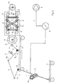
- the sheet 1 arriving from the printing press is transported by a conveyor chain 2 over the delivery stack 3.
- Grippers 4 on the conveyor chain guided over deflections 5 and 6 grasp the sheet 1 on its front edge.
- the sheet 1 is guided approximately horizontally into the delivery.
- a suction member 7 engages the rear edge of the sheet 1, which is released at the same time or with little overlap by the grippers 4 of the conveyor chain 2, so that the sheet 1 is lowered onto the sheet stack and thereby by the movement the suction member 7 is delayed and finally placed gently on the sheet stack 3.
- This delay of the sheet should take place as long as possible, so that the suction member must be accelerated to the sheet speed in the shortest possible way so that it can take over the sheet without relative speed to the sheet and return to the starting position at low speed when it takes the sheet released for storage on the delivery pile.
- This movement is achieved by a drive member from a cam 8, which is rotatably mounted about a horizontal shaft in the carriage 9, which carries all parts for the format adjustment, and whose horizontal adjustment option is illustrated by the circles symbolically indicated on the underside of the carriage 9.
- the suction member is one with its axis parallel to the axis of rotation 10 arranged shaft 11 movable.
- a roller 12 is pressed against the circumference of the cam plate 8 in a manner known per se by spring force, for example by a tension spring 35 according to FIG. 2, which roller is mounted on the free end of a short lever 13 of a four-link mechanism consisting of several levers, which forms the transmission mechanism .
- Another lever 14 is fixed to the shaft 11. Its free end is connected in the joint 17a to one end of a lever 15, the other end of which is connected in the joint 17b to a lever 16 which has a rigid connection with the lever 13 supporting the bearing of the roller 12 or is integral therewith is trained.
- the two levers 13 and 16 have a common joint 17c, which is arranged on the carriage 9.
- the lever 14 is also mounted on the slide 9 via the shaft 11 in the joint 17d.
- a sprocket 18 is fixedly connected, which is driven by a drive chain 19 directly from a sprocket 20 of the machine drive.
- the drive chain 19 passes through a chain store 21, which holds both chain runs 19a and 19b under uniform tension.
- the sprocket 18 on the cam 8 can be adjusted at a distance from the sprocket 20, but the phase position between the two sprockets 18 and 20 is retained. This enables format adjustments and speed changes of the machine without influencing the adjusted position and movement of the suction element 7 of the delivery sheet brake.
- both chain runs 19a and 19b are guided over a plurality of deflection rollers 22 and 23, the chain runs 19a and 19b alternately partially wrapping around the rollers 22 and 23 respectively assigned to them.
- the rollers 22 supporting the one chain center 19a are supported on a common carrier 24 and the rollers 23 supporting the other chain center 19b are supported on a common carrier 25, both of which are pressed apart by coil springs 26 and 27 and by at least one scissor cross 33 made of two in the Middle 34 hinged tabs, one end of which in one carrier and the opposite ends in the other carrier are slidably guided parallel to one another, the parallel position of the guides being maintained relative to one another.
- the two are arranged at the ends of these beams
- Coil springs 26 and 27 push the carriers 24 and 25 apart and thus bring about constant tension in the conveyor chain 19, changes in the distance between the two sprockets 18 and 20 are thereby compensated for without phase shift.
- FIG. 2 shows a suction element 7 comprising at least one suction device 28 and a housing 29, which guides the suction device 28 in a longitudinally movable manner, so that the suction device 28 can extend from the housing and be retracted into the housing.
- This movement takes place through the negative pressure in the line to the suction device 28 and is controlled by the contact of the sheet 1 with the suction device 28.
- the suction device 28 is moved out of the housing, this movement being able to take place, for example, by centrifugal force or by the negative pressure in the suction line connected to a vacuum pump 31.
- the suction device As soon as the suction device has grasped the rear edge of the sheet 1 and the suction opening of the suction device 28 is closed by the sheet 1, the negative pressure in the supply line to the suction device pulls it into the housing. This lowering movement of the suction cup makes the path of the deceleration phase lengthened because the suction opening of the suction cup moves on an elliptical path.
- the suction member 7 After the sheet 1 has been released by the suction device 28, the suction member 7 returns to the starting position and is then accelerated again to take over the next sheet into the take-over position.
- the sheet can be sucked in and released in a known manner, for example by a rotary valve 32 driven by the machine.
- a suction disk 30 is provided, which is fastened on the shaft 11 instead of the housing 29 of a suction device 28.
- a suction disc 30 is also moved by a transmission gear consisting of a plurality of levers 13, 14, 17, and 17 d, which are connected to one another by joints 17a, 17b, 17c and 17d, via a roller 12 by a rotatingly driven cam 8.
- an electric drive motor for the suction disk can also be provided with a control by a rotation angle sensor which is arranged directly on the printing press, this motor being connected to the suction disk directly or via a gear.
Description
Die Erfindung betrifft eine Auslagebogenbremse für eine Bogendruckmaschine, welche die Merkmale nach dem Oberbegriff des Patentanspruches 1 aufweist.The invention relates to a delivery sheet brake for a sheet printing machine, which has the features according to the preamble of claim 1.
Diese Gattungsmerkmale sind aus der DE-OS 16 36 316 bekannt. Das Saugorgan wird bei dieser bekannten Ausbildung durch einen Sauger gebildet, dessen Träger durch eine Hebelführung abgestützt ist, deren einer Hebel mit einem Exenter eines gleichförmig umlaufenden ersten Antriebsgliedes verbunden ist, welches die Hub- und Senkbewegungen des Saugers bewirkt, und deren anderer Hebel mit einem zweiten Antriebsglied gekoppelt ist, welches die horizontalen Bewegungen des Saugers auslöst. Dieses zweite Antriebsglied besteht aus einer Kurvenscheibe, gegen die eine Rolle gehalten wird, welche an einem Zahnsegment gelagert ist, welches in ein mit dem Hebel auf gleicher Welle befestigtes Zahnrad eingreift. Ein solcher Antrieb für die Auslagebogenbremse ermöglicht das Anheben des Saugers gegen die hintere Kante des etwa horizontal in die Auslage einlaufenden Bogens durch das eine Antriebsglied und gleichzeitig eine Beschleunigung der Horizontalbewegung des Saugers auf etwa Bogengeschwindigkeit durch das andere Antriebsglied aus einer Ausgangsposition heraus auf einem möglichst kurzen Wege. Nach der Übernahme des Bogens durch den Sauger in der Übernahmeposition, die zeitlich mit der Freigabe des Bogens durch die Transportmittel des Auslegers zusammenfällt oder sich mit dieser geringfügig überschneidet, wird der Sauger durch das erstere Antriebsglied gegen den Auslagestapel abgesenkt und gleichzeitig auf einem möglichst langen Wege durch das andere Antriebsglied verzögert, bevor der Sauger den Bogen in der Freigabeposition losläßt und mit relativ hoher Geschwindigkeit in die Ausgangsposition zurückkehrt, wobei ebenfalls beide Antriebsglieder zusammenwirken. Beide Antriebsglieder sind über Zahnräder und Antriebsketten mit dem Antrieb des Fördermittels im Ausleger verbunden. Die Druckschrift enthält keine Angaben über die Justierung der Saugerstellung und des Saugerantriebes im Falle der Formatänderung der zu bedruckenden Bogen. Da die Antriebsmittel für den Sauger mit diesem formschlüssig verbunden und demzufolge auf dem Schlitten für die Formatverstellung angeordnet sind, ist bei einer eventuellen Formatänderung der zu bedruckenden Bogen eine Justierung der Auslagebogenbremse vorzunehmen. Das ist zeitraubend und führt bei Fehleinstellungen zu Abschmierungen und zu einem ungenauen Papierlauf, insbesondere bei hoher Druckgeschwindigkeit. Die aus dieser Druckschrift bekannten Antriebe des Saugers der Auslagebogenbremse sind sehr aufwendig.These generic features are known from DE-OS 16 36 316. The suction member is formed in this known embodiment by a suction device, the support of which is supported by a lever guide, one lever of which is connected to an eccentric of a uniformly rotating first drive element, which brings about the lifting and lowering movements of the suction device, and the other lever of which second drive member is coupled, which triggers the horizontal movements of the vacuum cleaner. This second drive element consists of a cam disk, against which a roller is held, which is mounted on a toothed segment which engages in a gearwheel fastened to the lever on the same shaft. Such a drive for the delivery sheet brake enables the suction cup to be lifted against the rear edge of the sheet that runs approximately horizontally into the delivery by the one drive member and at the same time the horizontal movement of the suction device is accelerated to about the sheet speed by the other drive member from a starting position as short as possible Ways. After the sheet is taken over by the suction device in the take-over position, which coincides with the release of the sheet by the delivery means of the delivery arm or overlaps slightly with this, the suction device is lowered by the first drive element against the delivery stack and at the same time as long as possible decelerated by the other drive member before the suction device releases the sheet in the release position and returns to the starting position at a relatively high speed, whereby also interact both drive links. Both drive links are connected to the drive of the conveying means in the boom via gear wheels and drive chains. The publication contains no information about the adjustment of the suction position and the suction drive in the event of a change in the format of the sheets to be printed. Since the drive means for the suction device are positively connected to it and are consequently arranged on the slide for the format adjustment, the delivery sheet brake must be adjusted if the format of the sheet to be printed is changed. This is time-consuming and leads to greasing and inaccurate paper feed, especially at high printing speeds. The drives of the suction device of the delivery sheet brake known from this publication are very complex.
Auch die US-PS 2 130 841 zeigt eine Auslagebogenbremse, bei der die vertikalen und die horizontalen Bewegungen eines Saugers durch getrennte Antriebsmittel erreicht werden. Auf die durch Formatänderungen der zu bedruckenden Bogen ausgelösten Probleme nimmt auch diese Druckschrift keine Rücksicht.The US-PS 2 130 841 shows a delivery sheet brake, in which the vertical and horizontal movements of a suction cup are achieved by separate drive means. This publication also does not take into account the problems caused by changes in the format of the sheets to be printed.
Es ist Aufgabe der Erfindung, eine weitere Optimierung der Laufsicherheit der Bogen in der Bogenauslage, unabhängig von der Beschaffenheit der zu bedruckenden Bogen, vor allem bei hohen Maschinenlaufgeschwindigkeiten, zu erreichen und Formatverstellungen ohne zusätzliche Verstellung an der Auslagebogenbremse phasenneutral mit den Druckwerken zu ermöglichen.It is an object of the invention to achieve a further optimization of the running reliability of the sheets in the sheet delivery, regardless of the nature of the sheets to be printed, especially at high machine running speeds, and to enable format adjustments with the printing units without an additional adjustment on the delivery sheet brake.
Diese Aufgabe löst die Erfindung durch die Merkmale nach dem Kennzeichen des Patentanspruches 1.The invention solves this problem by the features according to the characterizing part of patent claim 1.
Dadurch erfolgt der Antrieb des Saugorgans der Auslagebogenbremse phasenneutral unmittelbar durch den Antrieb der Druckmaschine. Dieser phasenneutrale Antrieb wird bei eventueller Formatverstellung der zu bedruckenden Bogen nicht unterbrochen, wobei die Längenänderung der Antriebskette zwischen dem Antriebsglied des Saugorgans und der Maschine durch den Kettenspeicher ausgeglichen wird. Die unmittelbare Ankopplung des Antriebsgliedes für das Saugorgan an den Antrieb der Druckmaschine bewirkt, daß die auf die Bogengeschwindigkeit abgestimmte Geschwindigkeit des Saugorganes, unabhängig von der jeweiligen Maschinengeschwindigkeit, erhalten bleibt. Bei einer Formatverstellung bleibt die Phasenlage des Saugorgans gegenüber der Hinterkante des Bogens ebenfalls erhalten. Formatverstellungen und Änderungen der Maschinenlaufgeschwindigkeit können bei laufender Maschine erfolgen, ohne daß die Phasenlage des Saugorgans in der Auslagebogenbremse dadurch beeinflußt wird, worin ein wesentlicher Vorteil des unter Verwendung der Erfindungsmerkmale gestalteten Antriebes des Saugorgans der Auslagebogenbremse unmittelbar von der Maschine aus zu sehen ist.As a result, the suction element of the delivery sheet brake is driven phase-neutral directly by the drive of the printing press. This phase-neutral drive is not interrupted if the format of the sheets to be printed is changed, the change in length of the drive chain between the drive element of the suction element and the machine being compensated for by the chain store. The direct coupling of the drive element for the suction element to the drive of the printing machine has the effect that the speed of the suction element, which is matched to the sheet speed, is maintained, irrespective of the respective machine speed. With a format adjustment, the phase position of the suction element relative to the rear edge of the sheet is also retained. Format adjustments and changes in the machine running speed can be carried out while the machine is running without the phase position of the suction element in the delivery sheet brake being influenced, which is a significant advantage of the drive of the suction member of the delivery sheet brake designed using the inventive features, which can be seen directly from the machine.
Vorteilhaft bildet eine Kurvenscheibe das Antriebsglied für das Saugorgan, wobei gegen diese Kurvenscheibe unter Federspannung eine Rolle gehalten wird, deren Bewegungen mittels eines Übersetzungsgetriebes auf das Saugorgan übertragen werden, welches auf dem Schlitten zur Formatverstellung um eine Querachse beweglich gelagert ist.Advantageously, a cam forms the drive element for the suction member, a roller being held against this cam under spring tension, the movements of which are transmitted to the suction member by means of a transmission gear which is movably mounted on the slide for format adjustment about a transverse axis.
Dieses Übersetzungsgetriebe ist bei einer vorteilhaften konstruktiven Gestaltung der Erfindungsmerkmale als ein Hebelgetriebe ausgebildet, welches vier Gelenke aufweist, von denen zwei Gelenke ortsfest auf dem verstellbaren Schlitten zur Formatverstellung angeordnet sind und Gelenklager für die einen Enden zweier Hebel bilden, deren andere Enden durch einen weiteren Hebel in den beiden anderen Gelenken beweglich miteinander verbunden sind, wobei einer der beiden ersteren Hebel mit einem auf dem Schlitten festen Gelenk starr mit einem Stützlager der Rolle an der Kurvenscheibe und der andere dieser beiden Hebel starr mit einer auf dem Schlitten gelagerten und sich mit seiner Achse quer zur Transportrichtung des Bogens ersteckenden, das Saugorgan tragenden Welle verbunden ist. Ein solches Viergelenkgetriebe aus gelenkig miteinander verbundenen Hebeln ist kostengünstig herzustellen, betriebssicher in der Funktion und ermöglicht relativ große Übersetzungsverhältnisse bei relativ geringem Bauvolumen.This transmission gear is designed in an advantageous constructive design of the features of the invention as a lever gear, which has four joints, of which two joints are fixed on the adjustable carriage for format adjustment and spherical bearings for the form one end of two levers, the other ends of which are movably connected to one another by a further lever in the other two joints, one of the first two levers having a joint fixed on the slide rigid with a support bearing of the roller on the cam disc and the other of these two Lever is rigidly connected to a shaft mounted on the slide and extending with its axis transverse to the transport direction of the sheet and carrying the suction element. Such a four-bar linkage from levers connected to one another in an articulated manner is inexpensive to manufacture, reliable in operation and enables relatively large transmission ratios with a relatively small construction volume.
Die Kombination der Kurvenrolle und der Kurvenführung für diese Kurvenrolle mit einem Viergelenkgetriebe ergibt wegen des großen erreichbaren Übersetzungsverhältnisses den weiteren Vorteil, daß das Saugorgan, insbesondere ein Sauger oder auch mehrere Sauger, den Bogen pro Maschinenumdrehung nur einmal berührt.The combination of the cam roller and the cam guide for this cam roller with a four-bar transmission results in the further advantage that the suction element, in particular one or more suction pads, only touches the sheet once per machine revolution because of the large transmission ratio that can be achieved.
Bevorzugte Ausbildungsmerkmale für die Gestaltung des Kettenspeichers enthalten die Ansprüche 3 bis 6.Preferred training features for the design of the chain store contain
Das Saugorgan kann entweder durch eine Saugscheibe oder durch einen Hubsauger gebildet werden, wobei ein Hubsauger kein eigenes Antriebsmittel für die Hubbewegung erfordert. Eine eventuelle Hubbewegung des Saugers kann gegebenenfalls unmittelbar durch den Unterdruck im Sauger bewirkt und durch das Anlegen des Bogens an den Sauger gesteuert werden.The suction element can either be formed by a suction disc or by a lifting suction device, wherein a lifting suction device does not require its own drive means for the lifting movement. A possible lifting movement of the suction device can, if necessary, be brought about directly by the negative pressure in the suction device and can be controlled by applying the sheet to the suction device.
Die Zeichnung zeigt in schematischer Darstellung die Anordnung der Erfindungsmerkmale und deren Ausgestaltung.The drawing shows a schematic representation of the arrangement of the features of the invention and their configuration.
Es zeigen:
- Figur 1 eine Seitenansicht einer Bogenauslage mit Auslagebogenbremse,
- Figur 2 einen Antrieb eines das Saugorgan bildenden Saugers und
Figur 3 einen Antrieb für eine das Saugorgan bildende Saugscheibe.
- FIG. 1 shows a side view of a sheet delivery with delivery sheet brake,
- Figure 2 shows a drive of a suction device forming the suction member and
- Figure 3 shows a drive for a suction disc forming the suction member.
Der aus der Druckmaschine ankommende Bogen 1 wird durch eine Förderkette 2 über den Auslagestapel 3 transportiert. Dabei erfassen Greifer 4 an der über Umlenkungen 5 und 6 geführten Förderkette den Bogen 1 an dessen Vorderkante. Der Bogen 1 wird etwa horizontal in die Auslage geführt. Am Ende dieser Bewegung greift ein Saugorgan 7 an die Hinterkante des Bogens 1 an, der zur gleichen Zeit oder mit geringer zeitlicher Überdeckung von den Greifern 4 der Förderkette 2 freigegeben wird, so daß der Bogen 1 sich auf den Bogenstapel absenkt und dabei durch die Bewegung des Saugorgans 7 verzögert und schließlich sanft auf den Bogenstapel 3 abgelegt wird. Diese Verzögerung des Bogens soll auf möglichst langem Wege erfolgen, so daß das Saugorgan auf möglichst kurzem Wege bis auf die Bogengeschwindigkeit beschleunigt werden muß, damit es den Bogen ohne Relativgeschwindigkeit zum Bogen übernehmen kann und mit niedriger Geschwindigkeit in die Ausgangsposition zurückkehrt, wenn es den Bogen zur Ablage auf dem Auslagestapel freigegeben hat. Diese Bewegung wird durch ein Antriebsglied aus einer Kurvenscheibe 8 erreicht, die um eine horizontale Welle drehbar im Schlitten 9 gelagert ist, der alle Teile für die Formatverstellung trägt, und dessen horizontale Verstellmöglichkeit durch die an der Unterseite des Schlittens 9 symbolisch angegebenen Kreise verdeutlicht wird. Auf diesem Schlitten 9 ist auch das Saugorgan um eine mit seiner Achseparallel zur Drehachse 10 angeordneten Welle 11 beweglich. Gegen den Umfang der Kurvenscheibe 8 wird in an sich bekannter Weise durch Federkraft, z.B. durch eine Zugfeder 35 lt. Figur 2, eine Rolle 12 gepreßt, die am freien Ende eines kurzen Hebels 13 eines Viergelenkgetriebes aus mehreren Hebeln gelagert ist, welches das Übersetzungsgetriebe bildet. Ein weiterer Hebel 14 ist fest mit der Welle 11 verbunden. Sein freies Ende ist in dem Gelenk 17a mit dem einen Ende eines Hebels 15 verbunden, dessen anderes Ende in dem Gelenk 17b mit einem Hebel 16 verbunden ist, der eine starre Verbindung mit dem die Lagerung der Rolle 12 abstützenden Hebel 13 aufweist oder einstückig mit diesem ausgebildet ist. Die beiden Hebel 13 und 16 weisen ein gemeinsames Gelenk 17c auf, welches auf dem Schlitten 9 angeordnet ist. Auch der Hebel 14 ist über die Welle 11 in dem Gelenk 17d auf dem Schlitte 9 gelagert. Durch geeignete Abstimmung der Hebellängen lassen sich mit einfachen Mitteln Übersetzungsverhältnisse in weiten Grenzen erreichen.The sheet 1 arriving from the printing press is transported by a conveyor chain 2 over the
Mit der Kurvenscheibe 8 ist ein Kettenrad 18 fest verbunden, welches durch eine Antriebskette 19 direkt von einem Kettenrad 20 des Maschinenantriebes angetrieben wird. Die Antriebskette 19 durchläuft einen Kettenspeicher 21, der beide Kettentrums 19a und 19b unter gleichmäßiger Spannung hält. Dadurch kann das Kettenrad 18 an der Kurvenscheibe 8 gegenüber dem Kettenrad 20 im Abstand verstellt werden, wobei jedoch die Phasenlage zwischen den beiden Kettenrädern 18 und 20 erhalten bleibt. Dies ermöglicht Formatverstellungen und Geschwindigkeitsänderungen der Maschine ohne Einfluß auf die justierte Lage und Bewegung des Saugorgans 7 der Auslagebogenbremse.With the
Bei dem Ausführungsbeispiel des in der Zeichnung dargestellten Kettenspeichers 21 sind beide Kettentrums 19a und 19b über mehrere Umlenkrollen 22 und 23 geführt, wobei die Kettentrums 19a bzw. 19b die ihnen jeweils zugeordneten Rollen 22 bzw. 23 abwechselnd teilweise umschlingen. Die den einen Kettentrum 19a abstützenden Rollen 22 sind an einem gemeinsamen Träger 24 und die den anderen Kettentrum 19b abstützenden Rollen 23 sind an einem gemeinsamen Träger 25 gelagert, die beide durch Schraubenfedern 26 und 27 auseinandergedrückt werden und durch wenigstens ein Scherenkreuz 33 aus zwei in der Mitte 34 gelenkig miteinander verbundenen Laschen, deren eine Enden in dem einen Träger und deren gegenüberliegende Enden in dem anderen Träger parallel zueinander verschiebbar geführt sind, wobei die Parallellage der Führungen zueinander aufrechterhalten wird. Die beiden an den Enden dieser Träger angeordneten
Schraubenfedern 26 und 27 drücken die Träger 24 und 25 auseinander und bewirken damit eine stets gleichbleibende Spannung der Förderkette 19, Abstandsänderungen der beiden Kettenräder 18 und 20 voneinander werden dadurch ohne Phasenverschiebung kompensiert.In the embodiment of the
Coil springs 26 and 27 push the
Die Figur 2 zeigt ein Saugorgan 7 aus wenigstens einem Sauger 28 und einem Gehäuse 29, welches den Sauger 28 längsbeweglich führt, so daß der Sauger 28 aus dem Gehäuse ausfahren und in das Gehäuse zurückgezogen werden kann. Diese Bewegung erfolgt durch den Unterdruck in der Leitung zum Sauger 28 und wird durch die Anlage des Bogens 1 am Sauger 28 gesteuert. In der Beschleunigungsphase wird der Sauger 28 aus dem Gehäuse ausgefahren, wobei diese Bewegung zum Beispiel durch Fliehkraft oder auch durch den Unterdruck in der an eine Vakuumpumpe 31 angeschlossenen Saugleitung erfolgen kann. Sobald der Sauger die Hinterkante des Bogens 1 erfaßt hat und die Saugöffnung des Saugers 28 durch den Bogen 1 verschlossen ist, zieht der Unterdruck in der Zuleitung zum Sauger diesen in das Gehäuse hinein. Durch diese Absenkbewegung des Saugers wird der Weg der Verzögerungsphase verlängert, weil sich die Saugöffnung des Saugers auf einer elliptischen Bahn bewegt. Nach Freigabe des Bogens 1 durch den Sauger 28 kehrt das Saugorgan 7 in die Ausgangslage zurück und wird dann zur Übernahme des nächsten Bogens erneut bis in die Übernahmeposition beschleunigt. Das Ansaugen des Bogens und dessen Freigabe kann in bekannter Weise, zum Beispiel durch ein von der Maschine angetriebenes Drehventil 32, erfolgen.FIG. 2 shows a
Anstelle des Saugers ist bei dem Ausführungsbeispiel der Figur 3 eine Saugscheibe 30 vorgesehen, die anstelle des Gehäuses 29 eines Saugers 28 auf der Welle 11 befestigt ist. Auch eine solche Saugscheibe 30 wird durch ein Übersetzungsgetriebe aus mehreren durch Gelenke 17a, 17b, 17c und 17d miteinander verbundenen Hebeln 13,14,15,16 über eine Rolle 12 von einer umlaufend angetriebenen Kurvenscheibe 8 bewegt. Anstelle eines solchen Antriebes kann aber auch ein elektrischer Antriebsmotor für die Saugscheibe mit einer Steuerung durch einen Drehwinkelaufnehmer, der unmittelbar an der Druckmaschine angeordnet ist, vorgesehen sein, wobei dieser Motor direkt oder über ein Getriebe mit der Saugscheibe verbunden ist.
Claims (9)
- Sheet slow-down device in the delivery of a sheet-fed printing press, comprising a suction device (7) arranged on an adjustable slide (9) for format change-over, said suction device (7) gripping a sheet (1) at its rear edge and in its movement being guided on a closed-loop path past a sheet transfer position and a sheet release position, whereas said suction device (7) is connected with a drive member (8) through a stepup gearing having a toggle joint, said drive member (8), while being equally arranged on said slide (9) and moving on the same said closed-loop path, accelerates said suction device (7) in front of said sheet transfer position to sheet speed and slows down said suction device (7) between said sheet transfer and sheet release positions,
characterized
in that a chain wheel (18) at said drive member (8) on said adjustable slide (9) and a chain wheel (20) of the printing press drive are directly connected with each other through a drive chain (19) having a chain storage (21) which compensates a change in length of said drive chain (19) without phase displacement of said chain wheels (18, 20). - Sheet slow-down device according to claim 1,
characterized
in that the drive member on the slide (9) consists of a cam disk (8), and the stepup gearing consists of a roll (12) held against said cam disk (8) by the tension of a spring, and of levers (13, 14, 16) of different lengths which are linked to each other on one side and are disposed on said slide (9) on the other side, with one of said levers bearing said roll (12) which rests against said cam disk (8). - Sheet slow-down device according to claim 1,
characterized
in that the chain storage (21) for both chain strands (19a, 19b) of the drive chain (19) comprises guide rolls (22, 23) which are being loaded through spring force in a direction towards the outside. - Sheet slow-down device according to claim 3,
characterized
in that the guide rolls (22, 23) for both chain strands (19a, 19b) are mounted on carriers (24, 25), and that said carriers (24, 25) are connected with each other by means of a parallel construction (33). - Sheet slow-down device according to claim 4,
characterized
in that the parallel construction consists of at least one scissors cross (33), with the one ends of said scissors cross (33) being respectively guided slidingly in parallel with the one carrier (24) and its opposite ends in parallel with the other carrier (25). - Sheet slow-down device according to claims 3, 4 and 5,
characterized
in that both carriers (24, 25) for the guide rolls (22, 23) are loaded through spiral springs (26, 27) in a direction towards the outside. - Sheet slow-down device according to claims 1 and 2,
characterized
in that the stepup gearing is designed as a lever gearing, comprising four links (17a, 17b, 17c, 17d), of which two links (17c, 17d) are fixedly arranged on the slide (9) for format change-over and form ball-and-socket joints for the one ends of two levers (15, 16), with the other ends of said two levers (15, 16) being movably connected to each other in the two other links (17a, 17b) through a further lever (15), whereas one of the two first levers (14, 16), with its link (17c) being fixed on said slide (9), is rigidly connected with the supporting bearing for the roll (12) at the cam disk-(8), and the other one of said two levers (14, 16) is rigidly fastened to a shaft (11) being supported on said slide (9), with the axis of said shaft (11) extending transverse to the transport direction of the sheets. - Sheet slow-down device according to claims 1 and 2,
characterized
in that at least one suction disk (30) is provided as a suction device (7). - Sheet slow-down device according to claims 1 and 2,
characterized
in that at least one sucking element (28) is provided as a suction device, said sucking element (28) being guided in a manner that it can be lifted and lowered with respect to the pivotably mounted shaft (11), and being connected with the stepup gearing.
Applications Claiming Priority (2)
| Application Number | Priority Date | Filing Date | Title |
|---|---|---|---|
| DE3836254A DE3836254C1 (en) | 1988-10-25 | 1988-10-25 | |
| DE3836254 | 1988-10-25 |
Publications (3)
| Publication Number | Publication Date |
|---|---|
| EP0365847A2 EP0365847A2 (en) | 1990-05-02 |
| EP0365847A3 EP0365847A3 (en) | 1990-11-22 |
| EP0365847B1 true EP0365847B1 (en) | 1993-01-27 |
Family
ID=6365839
Family Applications (1)
| Application Number | Title | Priority Date | Filing Date |
|---|---|---|---|
| EP89117718A Expired - Lifetime EP0365847B1 (en) | 1988-10-25 | 1989-09-26 | Retarding device for the delivery end of a sheet-printing machine |
Country Status (6)
| Country | Link |
|---|---|
| US (1) | US5011125A (en) |
| EP (1) | EP0365847B1 (en) |
| JP (1) | JPH02169462A (en) |
| CN (1) | CN1016769B (en) |
| CA (1) | CA1325022C (en) |
| DE (2) | DE3836254C1 (en) |
Families Citing this family (7)
| Publication number | Priority date | Publication date | Assignee | Title |
|---|---|---|---|---|
| DE4435988A1 (en) * | 1994-10-08 | 1996-04-11 | Heidelberger Druckmasch Ag | Device for braking sheets |
| DE10239707B4 (en) * | 2002-08-29 | 2007-09-20 | Koenig & Bauer Aktiengesellschaft | Device for storing sheets in the delivery of a sheet-processing machine |
| DE10239709B4 (en) * | 2002-08-29 | 2004-08-26 | Koenig & Bauer Ag | Device for storing sheets in the delivery of a sheet-processing machine |
| DE10343428B4 (en) | 2002-10-25 | 2021-02-25 | Heidelberger Druckmaschinen Ag | Sheet-fed rotary printing machine with a post-gripper boom |
| US7708277B2 (en) * | 2008-03-10 | 2010-05-04 | Heidelberger Druckmaschinen Ag | Sheet delivery and sheet-processing printing machine |
| DE102009008856B4 (en) * | 2008-03-10 | 2018-02-22 | Heidelberger Druckmaschinen Ag | sheet delivery |
| US10150629B2 (en) | 2012-12-27 | 2018-12-11 | Ace Denken Co., Ltd. | Paper sheet conveyance device and separation/collection device |
Family Cites Families (7)
| Publication number | Priority date | Publication date | Assignee | Title |
|---|---|---|---|---|
| USRE25283E (en) * | 1962-11-06 | Sheet delivery slowdown | ||
| US2130841A (en) * | 1936-06-09 | 1938-09-20 | Cottrell C B & Sons Co | Delivery mechanism for printing presses |
| US2208978A (en) * | 1938-06-15 | 1940-07-23 | Harris Seybold Potter Co | Sheet delivery mechanism |
| BE487817A (en) * | 1947-10-25 | |||
| US2799499A (en) * | 1953-12-11 | 1957-07-16 | Miehle Goss Dexter Inc | Pneumatic sheet separating and feeding apparatus |
| US3378256A (en) * | 1966-03-22 | 1968-04-16 | Harris Intertype Corp | Sheet delivery slowdown |
| DE2035294A1 (en) * | 1970-07-16 | 1972-01-20 | Mabeg Maschinenbau Gmbh Nachf | Separating and conveying suction cups for sheet feeders |
-
1988
- 1988-10-25 DE DE3836254A patent/DE3836254C1/de not_active Expired - Lifetime
-
1989
- 1989-09-14 CA CA000611480A patent/CA1325022C/en not_active Expired - Fee Related
- 1989-09-26 DE DE8989117718T patent/DE58903400D1/en not_active Expired - Fee Related
- 1989-09-26 EP EP89117718A patent/EP0365847B1/en not_active Expired - Lifetime
- 1989-10-25 CN CN89107978A patent/CN1016769B/en not_active Expired
- 1989-10-25 JP JP1276170A patent/JPH02169462A/en active Pending
- 1989-10-25 US US07/426,963 patent/US5011125A/en not_active Expired - Lifetime
Also Published As
| Publication number | Publication date |
|---|---|
| EP0365847A2 (en) | 1990-05-02 |
| DE58903400D1 (en) | 1993-03-11 |
| DE3836254C1 (en) | 1990-05-10 |
| CN1042127A (en) | 1990-05-16 |
| US5011125A (en) | 1991-04-30 |
| CA1325022C (en) | 1993-12-07 |
| CN1016769B (en) | 1992-05-27 |
| JPH02169462A (en) | 1990-06-29 |
| EP0365847A3 (en) | 1990-11-22 |
Similar Documents
| Publication | Publication Date | Title |
|---|---|---|
| DE4011286C2 (en) | ||
| DE10343428B4 (en) | Sheet-fed rotary printing machine with a post-gripper boom | |
| DE2058606C3 (en) | Device for the continuous conveying and alignment of separated sheets | |
| EP0103104B1 (en) | Device for advancing sheets or batches of sheets | |
| DE3531113C2 (en) | ||
| EP0365847B1 (en) | Retarding device for the delivery end of a sheet-printing machine | |
| EP0054735A2 (en) | Device for producing rolls of flexible sheets wound in staggered overlapping formation | |
| DE2407752A1 (en) | METHOD AND DEVICE FOR DEPLOYING BOWS | |
| DE1561146B2 (en) | DEVICE FOR ALIGNED FEEDING INDIVIDUAL SHEETS TO SHEET PROCESSING MACHINES | |
| DE19601470A1 (en) | Drag suction gear, in particular drag suction gear for a device for correcting angled bends | |
| EP1181228B1 (en) | Device for depositing sheets on a stack | |
| EP0365848B1 (en) | Retarding device for the delivery end of a sheet-printing machine | |
| DE2637218B1 (en) | Sheet feeder | |
| EP0257366B1 (en) | Device for the registered positioning of a sheet on the feedboard of a rotary printing press | |
| DE2362104B2 (en) | Sheet feeder with feed grippers | |
| DE3107807C2 (en) | Sheet accelerator | |
| EP1310443A2 (en) | Sheet feeder | |
| DE4035907C1 (en) | Printing machine paper sheet feeder and aligner - has feed members on shafts, rotatably and laterally displaceably mounted w.r.t. to sheet feed | |
| DE1536483C3 (en) | Machine for collating sheets into a stack of sheets | |
| DE3139290A1 (en) | Device for the production of imbricated band rolls consisting of flat flexible articles deposited in overlapping formation | |
| DE724130C (en) | Device for feeding the sheets separated from a stack to a printing press, folding machine or the like. | |
| DE4230568C2 (en) | Forerunner | |
| DE717807C (en) | Automatic sheet loading and unloading device for cylinder printing machines | |
| DE672497C (en) | Delivery device on high-speed presses | |
| DE2166340C3 (en) | Feed device for a film web having a series of pockets |
Legal Events
| Date | Code | Title | Description |
|---|---|---|---|
| PUAI | Public reference made under article 153(3) epc to a published international application that has entered the european phase |
Free format text: ORIGINAL CODE: 0009012 |
|
| 17P | Request for examination filed |
Effective date: 19890926 |
|
| AK | Designated contracting states |
Kind code of ref document: A2 Designated state(s): DE FR GB IT SE |
|
| PUAL | Search report despatched |
Free format text: ORIGINAL CODE: 0009013 |
|
| AK | Designated contracting states |
Kind code of ref document: A3 Designated state(s): DE FR GB IT SE |
|
| 17Q | First examination report despatched |
Effective date: 19920624 |
|
| GRAA | (expected) grant |
Free format text: ORIGINAL CODE: 0009210 |
|
| AK | Designated contracting states |
Kind code of ref document: B1 Designated state(s): DE FR GB IT SE |
|
| REF | Corresponds to: |
Ref document number: 58903400 Country of ref document: DE Date of ref document: 19930311 |
|
| ET | Fr: translation filed | ||
| ITF | It: translation for a ep patent filed |
Owner name: STUDIO JAUMANN |
|
| GBT | Gb: translation of ep patent filed (gb section 77(6)(a)/1977) |
Effective date: 19930329 |
|
| PGFP | Annual fee paid to national office [announced via postgrant information from national office to epo] |
Ref country code: FR Payment date: 19930909 Year of fee payment: 5 |
|
| PG25 | Lapsed in a contracting state [announced via postgrant information from national office to epo] |
Ref country code: SE Effective date: 19930927 |
|
| PLBE | No opposition filed within time limit |
Free format text: ORIGINAL CODE: 0009261 |
|
| STAA | Information on the status of an ep patent application or granted ep patent |
Free format text: STATUS: NO OPPOSITION FILED WITHIN TIME LIMIT |
|
| 26N | No opposition filed | ||
| PGFP | Annual fee paid to national office [announced via postgrant information from national office to epo] |
Ref country code: GB Payment date: 19940818 Year of fee payment: 6 |
|
| EUG | Se: european patent has lapsed |
Ref document number: 89117718.0 Effective date: 19940410 |
|
| PG25 | Lapsed in a contracting state [announced via postgrant information from national office to epo] |
Ref country code: FR Effective date: 19950531 |
|
| REG | Reference to a national code |
Ref country code: FR Ref legal event code: ST |
|
| PG25 | Lapsed in a contracting state [announced via postgrant information from national office to epo] |
Ref country code: GB Effective date: 19950926 |
|
| GBPC | Gb: european patent ceased through non-payment of renewal fee |
Effective date: 19950926 |
|
| PGFP | Annual fee paid to national office [announced via postgrant information from national office to epo] |
Ref country code: DE Payment date: 20021002 Year of fee payment: 14 |
|
| PG25 | Lapsed in a contracting state [announced via postgrant information from national office to epo] |
Ref country code: DE Free format text: LAPSE BECAUSE OF NON-PAYMENT OF DUE FEES Effective date: 20040401 |
|
| PG25 | Lapsed in a contracting state [announced via postgrant information from national office to epo] |
Ref country code: IT Free format text: LAPSE BECAUSE OF NON-PAYMENT OF DUE FEES;WARNING: LAPSES OF ITALIAN PATENTS WITH EFFECTIVE DATE BEFORE 2007 MAY HAVE OCCURRED AT ANY TIME BEFORE 2007. THE CORRECT EFFECTIVE DATE MAY BE DIFFERENT FROM THE ONE RECORDED. Effective date: 20050926 |