EP0364291A2 - Radialer Luftreifen für Flugzeuge - Google Patents
Radialer Luftreifen für Flugzeuge Download PDFInfo
- Publication number
- EP0364291A2 EP0364291A2 EP89310532A EP89310532A EP0364291A2 EP 0364291 A2 EP0364291 A2 EP 0364291A2 EP 89310532 A EP89310532 A EP 89310532A EP 89310532 A EP89310532 A EP 89310532A EP 0364291 A2 EP0364291 A2 EP 0364291A2
- Authority
- EP
- European Patent Office
- Prior art keywords
- intersecting
- breaker
- breaker ply
- ply
- tire
- Prior art date
- Legal status (The legal status is an assumption and is not a legal conclusion. Google has not performed a legal analysis and makes no representation as to the accuracy of the status listed.)
- Granted
Links
- 229920001971 elastomer Polymers 0.000 claims abstract description 55
- 239000005060 rubber Substances 0.000 claims abstract description 55
- 238000010030 laminating Methods 0.000 claims abstract description 4
- 238000000926 separation method Methods 0.000 description 23
- 230000000052 comparative effect Effects 0.000 description 22
- 238000010008 shearing Methods 0.000 description 18
- 238000012360 testing method Methods 0.000 description 17
- 239000000835 fiber Substances 0.000 description 15
- 230000001788 irregular Effects 0.000 description 11
- 230000009467 reduction Effects 0.000 description 11
- 238000004088 simulation Methods 0.000 description 8
- 229920002302 Nylon 6,6 Polymers 0.000 description 6
- 238000005096 rolling process Methods 0.000 description 6
- 239000004677 Nylon Substances 0.000 description 5
- 239000011324 bead Substances 0.000 description 5
- 238000005452 bending Methods 0.000 description 5
- 238000006073 displacement reaction Methods 0.000 description 5
- 238000003475 lamination Methods 0.000 description 5
- 229920001778 nylon Polymers 0.000 description 5
- 230000006378 damage Effects 0.000 description 4
- 239000002184 metal Substances 0.000 description 4
- 238000010276 construction Methods 0.000 description 3
- 230000008602 contraction Effects 0.000 description 3
- 230000000452 restraining effect Effects 0.000 description 3
- 230000007935 neutral effect Effects 0.000 description 2
- 239000004372 Polyvinyl alcohol Substances 0.000 description 1
- 229920000297 Rayon Polymers 0.000 description 1
- 229920002978 Vinylon Polymers 0.000 description 1
- 230000008859 change Effects 0.000 description 1
- 239000012141 concentrate Substances 0.000 description 1
- 230000000694 effects Effects 0.000 description 1
- 239000012634 fragment Substances 0.000 description 1
- 238000009434 installation Methods 0.000 description 1
- 230000000116 mitigating effect Effects 0.000 description 1
- 238000012986 modification Methods 0.000 description 1
- 230000004048 modification Effects 0.000 description 1
- 229920000728 polyester Polymers 0.000 description 1
- 229920002451 polyvinyl alcohol Polymers 0.000 description 1
- 230000001737 promoting effect Effects 0.000 description 1
- 239000002964 rayon Substances 0.000 description 1
- 238000011084 recovery Methods 0.000 description 1
- 230000035939 shock Effects 0.000 description 1
Images


Classifications
-
- B—PERFORMING OPERATIONS; TRANSPORTING
- B60—VEHICLES IN GENERAL
- B60C—VEHICLE TYRES; TYRE INFLATION; TYRE CHANGING; CONNECTING VALVES TO INFLATABLE ELASTIC BODIES IN GENERAL; DEVICES OR ARRANGEMENTS RELATED TO TYRES
- B60C9/00—Reinforcements or ply arrangement of pneumatic tyres
- B60C9/18—Structure or arrangement of belts or breakers, crown-reinforcing or cushioning layers
- B60C9/26—Folded plies
-
- B—PERFORMING OPERATIONS; TRANSPORTING
- B60—VEHICLES IN GENERAL
- B60C—VEHICLE TYRES; TYRE INFLATION; TYRE CHANGING; CONNECTING VALVES TO INFLATABLE ELASTIC BODIES IN GENERAL; DEVICES OR ARRANGEMENTS RELATED TO TYRES
- B60C9/00—Reinforcements or ply arrangement of pneumatic tyres
- B60C9/18—Structure or arrangement of belts or breakers, crown-reinforcing or cushioning layers
- B60C9/20—Structure or arrangement of belts or breakers, crown-reinforcing or cushioning layers built-up from rubberised plies each having all cords arranged substantially parallel
- B60C9/2003—Structure or arrangement of belts or breakers, crown-reinforcing or cushioning layers built-up from rubberised plies each having all cords arranged substantially parallel characterised by the materials of the belt cords
- B60C9/2009—Structure or arrangement of belts or breakers, crown-reinforcing or cushioning layers built-up from rubberised plies each having all cords arranged substantially parallel characterised by the materials of the belt cords comprising plies of different materials
-
- B—PERFORMING OPERATIONS; TRANSPORTING
- B60—VEHICLES IN GENERAL
- B60C—VEHICLE TYRES; TYRE INFLATION; TYRE CHANGING; CONNECTING VALVES TO INFLATABLE ELASTIC BODIES IN GENERAL; DEVICES OR ARRANGEMENTS RELATED TO TYRES
- B60C9/00—Reinforcements or ply arrangement of pneumatic tyres
- B60C9/18—Structure or arrangement of belts or breakers, crown-reinforcing or cushioning layers
- B60C9/20—Structure or arrangement of belts or breakers, crown-reinforcing or cushioning layers built-up from rubberised plies each having all cords arranged substantially parallel
- B60C9/22—Structure or arrangement of belts or breakers, crown-reinforcing or cushioning layers built-up from rubberised plies each having all cords arranged substantially parallel the plies being arranged with all cords disposed along the circumference of the tyre
-
- Y—GENERAL TAGGING OF NEW TECHNOLOGICAL DEVELOPMENTS; GENERAL TAGGING OF CROSS-SECTIONAL TECHNOLOGIES SPANNING OVER SEVERAL SECTIONS OF THE IPC; TECHNICAL SUBJECTS COVERED BY FORMER USPC CROSS-REFERENCE ART COLLECTIONS [XRACs] AND DIGESTS
- Y10—TECHNICAL SUBJECTS COVERED BY FORMER USPC
- Y10T—TECHNICAL SUBJECTS COVERED BY FORMER US CLASSIFICATION
- Y10T152/00—Resilient tires and wheels
- Y10T152/10—Tires, resilient
- Y10T152/10495—Pneumatic tire or inner tube
- Y10T152/10765—Characterized by belt or breaker structure
Definitions
- This invention relates to a radial tire for an aircraft.
- a radial tire for an aircraft has been known as disclosed in Japanese Patent Application Laid-open No. 57-201,704.
- the tire includes a toroidal carcass layer consisting of at least one carcass ply having cords embedded therein extending perpendicular to an equatorial plane of the tire, a tread rubber arranged radially outwardly of the carcass layer, and a breaker arranged between the carcass layer and the tread rubber and formed by laminating at least one layer of circumferential plies and at least one layer of a breaker ply.
- Each of the circumferential plies has cords embedded therein substantially parallel to the equatorial plane.
- the breaker ply has cords embedded therein and intersecting at angles of 10°-70° with respect to the equatorial plane.
- a radial tire for an aircraft is often injured to a depth arriving at breaker layers by stones, metal pieces and the like when rolling. If the circumferential plies as above described are arranged on an outermost layer of the breaker layer, the cords embedded in the circumferential ply will be broken.
- the tire disclosed in the above Japanese application includes a breaker ply arranged radially outwardly of the circumferential plies to prevent the peeling of the cords of the circumferential plies and the tread rubber developing in the circumferential directions when injured.
- the cords of the breaker ply are oblique to the tire equatorial plane so that when the tire is injured and one oblique cord is cut, the cut growing in a circumferential direction will encounter adjacent oblique cords which would obstruct the growth of the cut. Therefore, the peel-off can be prevented by such cords oblique to the equatorial plane of this tire.
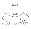
- a tire is subjected to bending deformation at contacting portions with a road when rolling as shown in Fig. 9.
- a belt layer consists of only breaker ply of a plurality of layers, the tire will undergo the following stresses. The farther radially inwardly from a neutral plane in a center of the belt layer or the nearer to the carcass layer, the larger tensile stresses occur. On the other hand, the farther radially outwardly from the neutral plane or the nearer to the tread rubber, the larger compressive stresses occur.
- the difference in the circumferential length is accumulated in the tread rubber of the shoulders from contacting to leaving the road to increase the shearing deformations in the circumferential directions.
- shearing deformations are rapidly restored when the tread rubber leaves the road so that the tread rubber at the shoulders are dragged on the road.
- a radial tire for an aircraft has been known as disclosed in Japanese Patent Application Laid-open No. 61-57,406.
- This tire includes a toroidal carcass layer consisting of at least one carcass ply having cords embedded therein intersecting at angles of 60°-90° with respect to an equatorial plane of the tire, a tread rubber arranged radially outwardly of the carcass layer, and a belt layer arranged between the carcass layer and the tread rubber and made of a lamination of at least one circumferential ply and at least one breaker ply.
- the circumferential ply has cords made of organic fibers such as nylon embedded therein and substantially in parallel with the equatorial plane.
- the breaker ply has cords made of organic fibers embedded therein and intersecting at angles less than 30° with respect to the equatorial plane.
- At least one breaker ply has a width (before being folded) wider than those of the other breaker plies and circumferential plies, and width edges of the breaker ply extending laterally from the other belt and circumferential plies are folded radially outwardly or radially inwardly onto the same side.
- one width edge may be folded radially outwardly and the other width edge may be folded radially inwardly.
- the folded width edges of the breaker ply are on the center thereof extending from one folded width edge to the other folded width edge.
- the width of the breaker ply after folded (ply width) is substantially equal to those of the other belt and circumferential plies.
- the cords 31 at the folded ends 34 and 35 are displaced in width directions of the breaker ply 33 (axial directions of the tire) by a restraining action of the cords 31 (inclined in reverse directions of the cords at the width center of the ply) of the folded width edges A and B.
- An influence by such a restraining action is maximum at the folded ends 34 and 35 and becomes smaller as approaching the center of the ply.
- a radial tire for an aircraft including a toroidal carcass layer consisting of at least one carcass ply having cords embedded therein intersecting at angles within a range of 70° to 90° with respect to an equatorial plane of the tire, a tread rubber arranged radially outwardly of the carcass layer, and a belt layer arranged between the carcass layer and the tread rubber and constructed by laminating at least one circumferential breaker ply and at least one intersecting breaker ply, said circumferential breaker ply having cords embedded therein substantially in parallel with said equatorial plane and said intersecting breaker ply having cords embedded therein intersecting at angles within a range of 10° to 70° with respect to the equatorial plane, according to the invention both radially outermost and innermost breaker plies of said belt layer are constituted by intersecting breaker plies.
- the circumferential breaker ply is arranged radially inwardly of a breaker ply positioned at the number of count from the innermost breaker ply corresponding to the number obtained by multiplying all the number of the breaker plies at a center of the belt by 3/4.
- both width edges of a radially innermost intersecting breaker ply are preferably folded radially outwardly, and the circumferential breaker ply is arranged radially outwardly of folded width edges of the intersecting breaker ply.
- the radially outermost breaker ply of the belt layer is constructed by an intersecting breaker ply or at least one intersecting breaker ply layer is arranged radial outwardly of the circumferential breaker ply. Therefore, even if the tire is injured arriving at cords of the circumferential breaker ply, any peeling of cords of the circumferential breaker ply developing in circumferential directions is prevented by the intersecting breaker ply arranged outwardly thereof to eliminate the peel-off as above described.
- the breaker ply arranged radially innermost of the belt layer or the breaker ply arranged adjacent the carcass layer is also constructed by intersecting breaker ply so that at least one layer of intersecting breaker ply is arranged radially inwardly of the circumferential breaker ply difficult in extending in circumferential directions.
- the intersecting breaker ply can be readily elongated in the circumferential directions by changes in cord angles and elongations of rubber between the cords, the difference in circumferential length between tread center and shoulders is substantially taken up thereby. Therefore, shearing deformations accumulated in the tread rubber when contacting the road become less to prevent irregular wear at shoulders.
- the reason why the circumferential breaker ply is arranged at the position as above described is as follows. External injuries caused by stones, metal pieces and the like arrive at various depths. In the event that the external injuries arrive at positions deeper than one fourth of the thickness of the belt layer measured from the outermost surface thereof, the tire is unavoidably discarded because even if the tire is recapped or recovered, the breaking pressure of the recapped tire is lower than a standardized pressure.
- the circumferential breaker ply is arranged at the positions above described to improve the possibility capable of being reused as a recapped or recovered tire.
- both the width edges of the intersecting breaker ply are folded outwardly so that the cord ends are brought near to the tire equatorial plane.
- the circumferential breaker ply is arranged radially outwardly of both width edges of the folded intersecting breaker ply so that both the ends of the intersecting breaker ply are externally hooped.
- both width edges of at least one intersecting breaker ply are folded on a width center portion of the intersecting breaker ply extending from one folded edge to the other folded edge, and at least one folded intersecting breaker ply is cut at its width center portion perpendicularly to a width direction of the breaker ply.
- the cords embedded in the intersecting breaker ply are constructed from organic fibers so that the cords shrink several percentages in longitudinal directions by vulcanizing heat in vulcanizing to reduce the width of the intersecting breaker ply.
- the intersecting breaker ply is a ply with its width edges being folded, intersecting angles of the cords in the proximity of the folded ends with respect to the equatorial plane become smaller owing to the reduction in ply width.
- At least one intersecting breaker ply layer among the folded intersecting breaker plies is severed at its width center portion so that the length of the cords embedded in the center portion of the breaker ply is made shorter than that in the prior art.
- the length of the cords is a length corresponding to a length from the one folded end to the severed portion or from the severed portion to the other folded end, and cord ends at the severed portion are free ends without being restrained.
- the tire according to the invention sufficiently endures high loads and high speeds when landing or flying-off.
- the tread rubber is formed with a plurality of shallow grooves having depths of 0.5-1.5 mm and spaced by distances of 3-10 mm from each other within ranges wider than a thickness of edges of the belt measured in a radial direction of the tire in buttress areas outwardly of contacting tread edges where round shoulder tread rubbers contact a road when filled with a normal inner pressure under a normal load.
- the shallow grooves preferably have groove edges chamfered to be round. With at least shallow grooves near to the contacting tread edges, curvatures of the edges of the shallow grooves on a side of sidewalls are preferably larger than those of the edges on a side of the contacting tread edges.
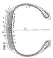
- the tire 1 includes a carcass layer 2 having a toroidal shape in a meridian section which is a radial section including a rotating axis of the tire.
- the carcass layer 2 consists of two or more layers, five layers 3 in this embodiment.
- the four layers of them on an inner side have edges viewed in width directions, which are turned-up around a pair of beads 4 from the inside to the outside to form turn-up plies.
- the outermost carcass ply 3 as a down ply extend along the outside of the turn-up portions of the carcass plies to the proximities of the beads 4.
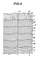
- carcass plies 3 include cords 5 (Fig. 4) embedded therein which intersect with each other with respect to an equatorial plane E at angles within a range of 70° to 90°, 90° in this embodiment.
- the cords 5 are made of organic fibers, nylon 66 (1890 d/3) in this embodiment.
- a tread rubber 6 is arranged radially outward of the carcass layer 2. Between the tread rubber 6 and the carcass layer 2 is arranged a belt layer 9 made of a lamination of a circumferential breaker ply 7 and intersecting breaker plies 8.
- the circumferential breaker ply 7 may be made of at least one layer, only one layer in this embodiment.
- the circumferential breaker ply 7 has a spirally wound cord or a number of cords embedded therein which are made of organic fibers, nylon 66 (1890 d/4) in this embodiment, in parallel with an equatorial plane E of the tire. In this case, it is preferable to arrange only one circumferential breaker ply 7 as described above. If a breaker ply 7 of more than two layers is arranged, the belt layer 9 will become difficult to extend and contract in circumferential directions so that difference in circumferential length between shoulders and center of the tread is not taken up sufficiently by extension and contraction of the belt layer 9 when the tire rolling being loaded. As a result, the shoulders are dragged on a road to cause irregular wear thereat.
- the intersecting breaker ply 8 has more than two layers, ten layers in this embodiment.
- Each of the breaker plies 8 includes cords 11 embedded therein which intersect at angles within a range of 10° to 70° with respect to the equatorial plane E, at an angle of approximately 20° in this embodiment.
- the cords 11 (Fig. 4) of the adjacent breaker plies 8 are arranged so as to intersect with each other.
- These cords 11 are made of organic fibers, nylon 66 (1890 d/3) in this embodiment.
- the radially outermost and innermost breaker plies of the belt layer 9 are constructed by intersecting breaker plies 8a and 8j.
- the circumferential breaker ply 7 is arranged between the outermost and innermost breaker plies.
- the circumferential breaker ply 7 is preferably arranged radially inwardly of the intersecting breaker ply positioned at the number by count from the innermost breaker ply 8a corresponding to the number obtained by multiplying all the number of the layers at the center of the belt 9 by 3/4.
- the breaker ply 7 is preferably positioned radially inwardly of the intersecting breaker ply 8g (although 11 multiplied 3/4 is 8.25, 8 is used because it must be a positive integral number).
- the breaker ply 7 is arranged at fifth from the radially innermost layer in this embodiment.
- the reason for such an arrangement of the breaker ply 7 is as follows. If depths of external cuts by stones and metal pieces are shallower than positions 1/4 of a thickness from the radially outermost of the belt layer 9 of a tire, it can be reused as a recovery or recapped tire by replacing with a new tread because a breaking pressure is less than the determined pressure. On the other hand, if a circumferential breaker ply 7 is arranged shallower than the position above described and cords of the breaker ply 7 are cut by stones and metal pieces, separations in rubber and between the rubber and the cords 10 will develop circumferentially from the cut by deformation and centrifugal forces when landing so that it could not be used as a recapped tire. Therefore, the circumferential breaker ply 7 is arranged radially inwardly of the 8th layer to improve the probability of being used as a recapped tire.
- Both width edges of the radially innermost intersecting breaker ply are preferably radially outwardly folded on the other breaker plies.
- the innermost and sixth intersecting breaker plies 8a and 8e are made longer than the other breaker plies, and both the width edges A and B of them are folded outwardly to surround the width edges of the second and third intersecting breaker plies 8b and 8c and the width edges of the seventh and eighth intersecting breaker plies 8f and 8g.
- the fourth and ninth intersecting breaker plies 8d and 8h are arranged between the width edges A and B of the intersecting breaker ply 8a and between the width edges A and B of the intersecting breaker ply 8e, respectively.
- the circumferential breaker ply 7 is preferably arranged radially outward of the folded width edges A and B of the innermost intersecting breaker ply 8a.
- the breaker ply 7 is arranged on the width edges A and B of the fourth layer or positioned as a fifth layer as above described.
- the reason for such an arrangement of the circumferential breaker ply 7 is as follows. With such an arrangement, the intersecting breaker ply 8a is clamped outwardly as a hoop by the circumferential breaker ply 7 to prevent the phenomenon that separations occurring at ply ends by stress concentrations would otherwise develop in circumferential directions by peeling of the intersecting breaker ply 8a caused by centrifugal forces during high speed running.
- the breaker ply arranged at the radially outermost of the belt layer 9 is constructed by the intersecting breaker ply 8j or at least one layer (six layers) of the intersecting breaker plies 8 is arranged radially outward of the circumferential breaker ply 7, even if the tire is externally injured to a depth arriving at the cords 10 of the circumferential breaker ply 7, any peeling of the breaker ply 7 developing in circumferential directions of the cords 10 is obstructed by the intersecting breaker plies 8 of the six layers arranged on the outside of thereof, thereby preventing the occurrence of the peel-off.
- the intersecting 16 breaker ply 8a since even the radially innermost breaker ply of the belt layer 9 or arranged adjacent the carcass layer 2 is constructed by the intersecting 16 breaker ply 8a, at least one layer (four layers in this embodiment) of the intersecting breaker ply 8 is arranged radially inwardly of the circumferential breaker ply 7 which is difficult to be elongated in circumferential directions.
- the intersecting breaker plies 8 can readily elongate in the circumferential directions with the aid of elongation of rubber between the cords 11 and angular displacements of the cords 11 when contacting the road, the difference in circumferential length between the tread center and the shoulders is substantially taken up by the elongations in the circumferential directions. Therefore, shearing deformations accumulated in the tread rubber 6 at the shoulders when contacting the road become less so that occurrence of the irregular wear at the shoulders is prevented.
- Tires of Example 1 were those of the embodiment above explained.
- Tires of Example 2 were those similar to those of the Example 1 with exception of a circumferential breaker ply being arranged between eighth and tenth intersecting breaker plies or being ninth layer as shown in Fig. 5.
- Tires of Comparative Example 1 had a circumferential breaker ply similar to that of the Example 1 but arranged radially outermost as shown in Fig. 6.
- Tires of Comparative Example 2 had a circumferential breaker ply similar to that of the Example 1 but arranged radially innermost as shown in Fig. 7.
- Tires of Comparative Example 3 included intersecting breaker plies of eleven layers laminated and being not folded as shown in Fig. 8.
- the tire size was H 46 ⁇ 18.0 R 20.
- Each of these tires was filled with inner pressure of 14.1 kg/cm2. The tire was then urged under a load of 44200 Lbs (20049 kg) against a drum. The drum was rotatively driven to drive the tire so as to increase the rotating speeds of the tire from 0 mile/h to 225 mile/h (362.1 km/h). Occurrence of standing waves was observed.
- a cut having a 4 cm length and extending in the rotating axis directions of the tire was formed in the width center of the breaker ply located radially outermost of the tire with a knife.
- the tire was filled with inner pressure of 14.1 kg/cm2.
- the tire was then urged under a load of 44200 Lbs (20049 kg) against the drum.
- the tire was rotatively driven under the condition so as to increase the speeds of the tire from 0 mile/h to 225 mile/h (362.1 km/h) and the load was then removed. Such a take-off simulation was repeated until the tire was broken or maximum of 50 times.
- Example 1 and Comparative Example 2 could be subjected to all the simulations. However, with the tires of Example 2, expansions occurred at injured portions at eighth simulations so that the test was stopped. In the tires of Comparative Example 1, parts of belt layers were peeled and flew in all directions at the first take-off simulation and therefore the test was stopped. The injured durability test was not carried out on the tires of Comparative Example 3.
- the tires were urged against the drum which driven the tires to effect a promoting wear test wherein average wear amounts in tire surfaces were measured at tread centers and shoulders.
- Irregular wear characteristics indicated by indexes were 106 and 103 with the tires of Examples 1 and 2 and 102, 135 and 103 with the tires of Comparative Examples 1, 2 and 3.
- the index 100 corresponded to the average wear amount at the tread center of each of the tires. A value nearer to 100 means that the wear was more uniform.
- the tire 21 includes a carcass layer 22 having a toroidal shape in a meridian section which is a radial section including a rotating axis of the tire.
- the carcass layer 22 consists of two or more layers, five layers 23 in this embodiment.
- the four layers of them on an inner side have edges viewed in width directions, which are turned-up around a pair of beads 24 and 25 from the inside to the outside to form turn-up plies.
- the outermost carcass ply 23 as a down ply extend along the outside of the turn-up portions of the carcass plies to the proximities of the beads 24.
- These carcass plies 23 include cords 27 embedded therein which intersect with each other with respect to an equatorial plane 26 at angles within a range of 70° to 90°, 90° in this embodiment.
- the cords 27 are made of organic fibers, nylon 66 (1890 d/3) in this embodiment.
- a tread rubber 30 is arranged radially outward of the carcass layer 22. Between the tread rubber 30 and the carcass layer 22 is arranged a belt layer 33 made of a lamination of a circumferential breaker ply 34 and intersecting breaker plies 36.
- the circumferential breaker ply 34 may be made of at least one layer, only one layer in this embodiment.
- the circumferential breaker ply 34 has a spirally wound cord 35 or a number of cords embedded therein which are made of organic fibers, nylon 66 (1890 d/4) in this embodiment, in parallel with an equatorial plane 26 of the tire.
- the intersecting breaker ply 36 has more than two layers, ten layers in this embodiment.
- Each of the breaker plies 36 includes cords 37 embedded therein at a rate of 32/(5 cm) which intersect at angles within a range of 10° to 70° with respect to the equatorial plane 26, at an angle of approximately 20° in this embodiment.
- the cords 37 of the adjacent breaker plies 36 are arranged so as to intersect with each other. These cords 37 are made of organic fibers, nylon 66 (1890 d/3) in this embodiment.
- cords 37, 35 and 27 may be made of rayon, polyester, vinylon, polyvinyl alcohol fibers or the like other than nylon. In case that these heat-shrinkable organic fibers are used, the cords 27, 35 and 37 will contract several percentages in longitudinal directions (about 8% with nylon) when vulcanizing.
- At least one intersecting breaker ply 36 is made wider than the other breaker plies.
- the innermost intersecting breaker ply 36a and the sixth intersecting breaker ply 36b counted from the innermost are made wider than the other intersecting breaker plies 36, and width edges A and B of the wide breaker plies 36a and 36b are folded outwardly to surround width edges of second and third intersecting breaker plies 36 and width edges of seventh and eighth intersecting breaker plies 36.
- the folded width edges A and B overlap the center C of the intersecting breaker plies 36a and 36b of portions of the breaker plies 36a and 36b extending from folded ends 44 and 45 on one side to folded ends 46 and 47 on the other side.
- fourth and ninth intersecting breaker plies 36 are arranged between the width edges A and B of the intersecting breaker ply 36a and between the width edges A and B of the intersecting breaker ply 36b, respectively.
- At least one intersecting breaker ply among the folded intersecting breaker plies 36a and 36b, or the intersecting breaker ply 36a in this embodiment is severed at the center C, in more detail on the equatorial plane 26.
- all the cords 37 embedded in the center C of the intersecting breaker ply 36a are severed at the center D, whose severed ends are free ends without being restrained.
- intersecting breaker plies 36 on the inner side nearer to the carcass layer 22 are subjected to larger bending deformation to cause larger shearing strains at belt ends. Therefore, in this embodiment, the inner intersecting breaker ply 36a among the folded intersecting breaker plies 36a and 36b is severed at its center C.
- the intersecting breaker ply 36b arranged on the outer side may be further severed at its center.
- vulcanizing is required.
- the cords 27, 35 and 37 constructed by heat-shrinkable organic fibers contract several percentages in longitudinal directions by vulcanizing heat so that ply widths of the respective plies, particularly intersecting breaker plies 36 become narrow.
- intersecting breaker plies 36 are those whose width edges are folded, intersecting angles of the cords 37 embedded in the proximity of the folded ends 44, 45, 46 and 47 with respect to the equatorial plane 26 become smaller owing to the reduction in ply widths.
- great shearing forces act on ply ends of the intersecting breaker plies 36a and 36b owing to deformations caused by contacting a road. Therefore, great shearing strains will occur in the rubber between the cords 37 of the ply ends (folded ends 44, 45, 46 and 47) by the great shearing forces in conjunction with the reduction in intersecting angles of the cords.
- the intersecting breaker ply 36a which will undergo larger shearing forces when being deformed in contacting the road is severed at the width center C so that lengths of the cords 37 embedded in the center C are made shorter than those in the prior art, one half of the length of the prior art, and the cord ends at the severed position D are free ends.
- the ends of the cords 37 in the proximity of the severed position D slide through the rubber, while the ends are contracting in vulcanizing so that only the ends of the cords are displaced. Since it is considered that total contracting amount of the cords 37 embedded in the width center C of the intersecting breaker ply 36a is substantially constant, the displacement of the cords 37 positioned at the folded ends 44 and 46 is reduced by the displacement of the ends of the cords 37 in the proximity of the severed position D so that the reduction in ply widths at the center C is mitigated.
- tires of two kinds were prepared.
- Tires of Example were those explained as the second embodiment and tires of Comparative Example were those similar to those of Example with exception of the radially innermost intersecting breaker ply which was not severed at its width center.
- the size of these tires was H 46 ⁇ 18.0 R 20.
- Figs. 12-14 illustrate other embodiments of the invention wherein intersecting breaker plies are in solid lines and circumferential breaker plies in broken lines.
- Fig. 12 illustrates third embodiment of the invention.
- an intersecting breaker ply 36b is severed at its center C at an equatorial plane 26 and width edges A and B of the breaker ply 36b extend to the proximity of the equatorial plane 26.
- Any intersecting breaker ply 36 to be arranged between the edges A and B is omitted.
- a circumferential breaker ply 34 is arranged radially outwardly of the outermost intersecting breaker ply 36.
- Other constructions and functions are similar to those of the second embodiment above described.
- Fig. 13 illustrates fourth embodiment of the invention.
- an intersecting breaker ply 36a is severed at its center at two locations so that the center portion C extend equal distances from an equatorial plane onto both sides.
- Other constructions and functions are similar to those of the second embodiment above descried.
- Fig. 14 illustrates fifth embodiment of the invention.
- an intersecting breaker ply 36b is severed at its center C at an equatorial plane 26 and a circumferential breaker ply 34 is arranged between a tenth intersecting breaker ply 36 counted from the innermost and width edges A and B of an intersecting breaker ply 36b and an eighth intersecting breaker ply 36 or is arranged as a ninth layer counted from the innermost.
- Other constructions and functions are similar to those of the second embodiment above described.
- the width edges A and B of the intersecting breaker plies 36a and 36b are folded in the same directions or radially outwardly.
- the width edges may be folded in different manner.
- one width edge may be folded radially outwardly and the other width edge may be folded radially inwardly or both the width edges may be folded radially inwardly or radially outwardly.
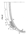
- Fig. 15 illustrates in section a principal part of a pneumatic radial tire for an aircraft according to the invention.
- the tire includes a carcass 51, a belt 52, sidewalls 53, round shoulder tread rubbers 54 and an inner liner 55.
- Reference numeral 56 denotes a contacting tread edge which is an edge of the tread in contact with a road when loaded with a rated load.
- the carcass is of course toroidal and consists of turn-up plies which are turn up around bead cores (not shown) and include organic fiber codes such as nylon arranged substantially in radial surfaces and a down ply covering the turn-up plies.
- the belt 52 is a multiple lamination made of rubber coated cord oblique cloths whose heat-contractible organic fiber cords such as nylon are arranged in parallel with each other.
- the belt 52 extends over the full width of the tread which contacts the road to surround a crown of the carcass 51.
- the multiple lamination may consist of two fold structural layers 52a and 52b, a separating layer 52c embraced between the fold structural layers 52a and 52b, and separating layers 52d and 52e arranged on the outside of the fold structural layer 52b.
- Each of the fold structural layers includes two inner layers and an outer layer wider than the inner layers so as to surround them by its width edges.
- the belt 52 contracts in width directions of the tire in vulcanizing for forming the tire so that the belt 52 assumes the position shown in broken lines when the vulcanizing is completed.
- a thickness of the multi-laminated belt 52 at one edge measured in a radial direction of the tire is indicated by t.
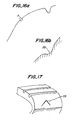
- the pneumatic tire above described comprises a plurality of shallow grooves 58 according to the invention.
- the grooves 58 are in a buttress area 57 outside each of the contacting tread edges 6 where the round shoulder tread rubber contacts the road when filled with normal inner pressure under a normal load.
- the grooves 58 have depths of 0.5-1.5 mm and are spaced from each other by 3-10 mm.
- the shallow grooves 58 are arranged in a row in an area extending wider than t which is the thickness of the multi-laminated belt 52. In order to avoid sharp edges of the shallow grooves 58, edges of the grooves are chamfered to be rounded. The rounded edges of the shallow groove 58 nearest to the contacting tread edge are preferably made smaller in curvature than those of the shallow edges 58 nearer to the sidewall.
- Depths of the shallow grooves 58 are preferably 0.5-1.5 mm for ensuring the reduction in the friction coefficient. If the depth of the shallow groove 58 is deeper than 1.5 mm, the rubber between the grooves are subjected to large deformations which would result in cracks at bottoms of the grooves 58. On the other hand, if the depth of the grooves 58 is less than 0.5 mm, it does not serve to reduce the friction coefficient. If the edges of the shallow grooves are sharp without being chamfered, the rubber in the proximity of the grooves 58 tends to broken by side forces.
- edges of the shallow groove 58 are chamfered to be rounded as shown in Fig. 16b. With at least the grooves 58 near to the contacting tread edge 56, curvatures of the edges of the grooves on the side of the sidewall should be larger than those of the edges on the contacting tread edge 56.
- Tires of H 46 ⁇ 18.0 R20 and having the rubber thickness in the buttress areas of 10 mm were produced by way of trial. Each of the tires was filled with 200 psi inner pressure and driven under a load of 44200 Lbs on the drum of the testing machine. During such a running, steering angles were increased from 0° to 15° in increments of 1° during which observing whether cracks occurred in the buttress areas.
- the shallow grooves 58 had 1 mm depth and were spaced 5 mm apart from each other and chamfered at edges with radii of curvatures of 6 mm and 1.5 mm on the tread side and the sidewall side, respectively.
- tires of Comparative Example 5 having shallow grooves of 3 mm depth were prepared. With these tires, cracks occurred in bottoms of the grooves at the steering angles of 13°. Without chamfering at edges of the grooves, edges were broken at the steering angles of 12°.
- tires of Comparative Example 6 having shallow grooves of 1 mm depth and 2.5 mm distances between the grooves were prepared without chamfering at edges of the grooves. Because of too narrow distances between the grooves, ribs between the grooves were broken at the steering angle of 8°.
- the pneumatic radial tire according to the invention can effectively prevent the shevron-shaped cracks in the rubber of rounded shoulders of the tire caused by violent side or lateral forces acting upon wheels of an aircraft landing on a runway, while being subjected to strong lateral wind. Therefore, it can remove the risk that such faults as cracks would develop into a great accident such as a burst, thereby contributing to the safe flying of aircrafts.
Landscapes
- Engineering & Computer Science (AREA)
- Mechanical Engineering (AREA)
- Tires In General (AREA)
Applications Claiming Priority (6)
| Application Number | Priority Date | Filing Date | Title |
|---|---|---|---|
| JP63258876A JP2604825B2 (ja) | 1988-10-14 | 1988-10-14 | 丸肩トレッドをもつ航空機用空気入りラジアルタイヤ |
| JP258876/88 | 1988-10-14 | ||
| JP324370/88 | 1988-12-22 | ||
| JP63324370A JPH02169304A (ja) | 1988-12-22 | 1988-12-22 | 航空機用ラジアルタイヤ |
| JP325622/88 | 1988-12-23 | ||
| JP63325622A JPH02171303A (ja) | 1988-12-23 | 1988-12-23 | 航空機用ラジアルタイヤ |
Publications (3)
| Publication Number | Publication Date |
|---|---|
| EP0364291A2 true EP0364291A2 (de) | 1990-04-18 |
| EP0364291A3 EP0364291A3 (de) | 1991-03-20 |
| EP0364291B1 EP0364291B1 (de) | 1994-12-21 |
Family
ID=27334769
Family Applications (1)
| Application Number | Title | Priority Date | Filing Date |
|---|---|---|---|
| EP89310532A Expired - Lifetime EP0364291B1 (de) | 1988-10-14 | 1989-10-13 | Radialer Luftreifen für Flugzeuge |
Country Status (3)
| Country | Link |
|---|---|
| US (1) | US5176769A (de) |
| EP (1) | EP0364291B1 (de) |
| ES (1) | ES2068901T3 (de) |
Cited By (6)
| Publication number | Priority date | Publication date | Assignee | Title |
|---|---|---|---|---|
| FR2661870A1 (fr) * | 1990-05-09 | 1991-11-15 | Sumitomo Rubber Ind | Pneumatique radial a grande vitesse pour forte charge. |
| EP0463875A3 (en) * | 1990-06-27 | 1992-05-13 | Sumitomo Rubber Industries, Co. Ltd | Motorcycle radial tyre |
| EP0479065A3 (en) * | 1990-10-01 | 1992-09-09 | The Goodyear Tire & Rubber Company | Belt structure for a radial pneumatic tire |
| EP0605177A1 (de) * | 1992-12-24 | 1994-07-06 | Bridgestone Corporation | Luft-Reifen |
| US5529105A (en) * | 1992-12-24 | 1996-06-25 | Bridgestone Corporation | Pneumatic tire including at least one tie-element layer with substantially orthogonally oriented cords |
| WO2017187032A1 (fr) | 2016-04-25 | 2017-11-02 | Compagnie Generale Des Etablissements Michelin | Pneu avion ayant une armature de carcasse à endurance améliorée |
Families Citing this family (11)
| Publication number | Priority date | Publication date | Assignee | Title |
|---|---|---|---|---|
| US20040163748A1 (en) * | 2003-02-24 | 2004-08-26 | Kiyoshi Ueyoko | Tire having a composite belt structure |
| US20100154965A1 (en) * | 2008-12-19 | 2010-06-24 | Roland Willibrord Krier | Offset zigzag belt structure for a pneumatic tire |
| US20100154964A1 (en) * | 2008-12-19 | 2010-06-24 | Francois Pierre Charles Gerard Georges | Pneumatic tire |
| US9168789B2 (en) | 2008-12-19 | 2015-10-27 | The Goodyear Tire & Rubber Company | Truck tire |
| US8079392B2 (en) * | 2008-12-19 | 2011-12-20 | The Goodyear Tire & Rubber Company | Alternating straight/wavy reinforcement structure for pneumatic tire |
| US20100154974A1 (en) * | 2008-12-19 | 2010-06-24 | Francois Pierre Charles Gerard Georges | Method of making a pneumatic tire |
| CN103415404B (zh) * | 2011-03-03 | 2015-08-19 | 株式会社普利司通 | 轮胎 |
| FR2997344B1 (fr) * | 2012-10-31 | 2014-11-21 | Michelin & Cie | Flanc de pneumatique pour vehicule lourd de type genie civil |
| FR3087387B1 (fr) * | 2018-10-19 | 2021-10-08 | Michelin & Cie | Procede de simulation de l'evolution temporelle d'un systeme physique en temps reel |
| US11833861B2 (en) | 2019-08-27 | 2023-12-05 | Bridgestone Americas Tire Operations, Llc | Tire with multiple body plies |
| CN111559204B (zh) * | 2020-05-18 | 2022-03-22 | 通力轮胎有限公司 | 一种有内胎全钢子午线防爆轮胎 |
Family Cites Families (19)
| Publication number | Priority date | Publication date | Assignee | Title |
|---|---|---|---|---|
| FR1362008A (fr) * | 1963-04-12 | 1964-05-29 | Mft Fr Pneumatiques Michelin | Perfectionnements aux enveloppes de pneumatiques |
| DE1480933A1 (de) * | 1964-03-26 | 1969-04-17 | Continental Gummi Werke Ag | Laufflaechenprofilierung fuer Fahrzeugluftreifen |
| FR1480333A (fr) * | 1966-03-30 | 1967-05-12 | Fr Du Pneu Englebert Soc | Ceinture de renforcement pour bande de roulement d'enveloppe de pneumatique |
| US3842884A (en) * | 1970-12-21 | 1974-10-22 | Uniroyal Ag | Radial ply tire with reinforcing belt |
| FR2316091A1 (fr) * | 1975-06-30 | 1977-01-28 | Uniroyal | Enveloppe de bandage pneumatique de roue |
| JPS5340088A (en) * | 1976-09-27 | 1978-04-12 | Toyo Tire & Rubber Co | Production of radial tire |
| FR2376763A1 (fr) * | 1977-01-05 | 1978-08-04 | Kleber Colombes | Pneumatique pour tracteurs agricoles ou engins similaires |
| DE2719798A1 (de) * | 1977-05-03 | 1978-11-16 | Uniroyal Ag | Hochbelastbarer stahlkord-guertelreifen, insbesondere fuer lastkraftwagen, schwer- und/oder grossfahrzeuge mit einer mindestens einlagigen radialkarkasse, vorzugsweise aus stahlkord, und einer mehrlagigen guertelartigen verstaerkung, welche wenigstens eine faltlage aus stahlkord und wenigstens eine weitere ungefaltete lage aus textilkord aufweist |
| FR2499475A1 (fr) * | 1981-02-12 | 1982-08-13 | Michelin & Cie | Pneumatique gros porteur dont l'armature de sommet comporte des cables circonferentiels thermoretractables, et son procede de fabrication |
| DE3202008A1 (de) * | 1981-02-12 | 1982-09-23 | Michelin & Cie. (Compagnie Générale des Etablissements Michelin), 63040 Clermont-Ferrand | Hochdruck-schwerlastluftreifen mit radialkarkassenbewehrung und verfahren zu seiner herstellung |
| CA1200746A (en) * | 1982-04-16 | 1986-02-18 | John R. Abbott | Tread reinforcement structure for pneumatic tires |
| GB8413093D0 (en) * | 1984-05-22 | 1984-06-27 | Apsley Metals Ltd | Tyres |
| JPH0741765B2 (ja) * | 1984-08-29 | 1995-05-10 | 住友ゴム工業株式会社 | 航空機用タイヤ |
| JPS61241203A (ja) * | 1985-04-17 | 1986-10-27 | Bridgestone Corp | 航空機用ラジアルタイヤ |
| US4688615A (en) * | 1985-05-28 | 1987-08-25 | The Goodyear Tire & Rubber Company | Reinforcing structure for a rubber article |
| JPS63121102A (ja) * | 1986-11-07 | 1988-05-25 | Matsushita Electric Ind Co Ltd | 磁気記録再生装置の回転ヘツド装置 |
| GB2201925B (en) * | 1987-03-12 | 1991-02-27 | Dunlop Ltd | Radial ply tyre |
| IT1223508B (it) * | 1987-12-17 | 1990-09-19 | Pirelli | Struttura di cintura di pneumatici per ruote di veicoli |
| JPH01223004A (ja) * | 1988-03-01 | 1989-09-06 | Bridgestone Corp | 高内圧・重荷重用空気入りラジアルタイヤ |
-
1989
- 1989-10-13 EP EP89310532A patent/EP0364291B1/de not_active Expired - Lifetime
- 1989-10-13 ES ES89310532T patent/ES2068901T3/es not_active Expired - Lifetime
- 1989-10-16 US US07/421,871 patent/US5176769A/en not_active Expired - Lifetime
Cited By (8)
| Publication number | Priority date | Publication date | Assignee | Title |
|---|---|---|---|---|
| FR2661870A1 (fr) * | 1990-05-09 | 1991-11-15 | Sumitomo Rubber Ind | Pneumatique radial a grande vitesse pour forte charge. |
| EP0463875A3 (en) * | 1990-06-27 | 1992-05-13 | Sumitomo Rubber Industries, Co. Ltd | Motorcycle radial tyre |
| US5441093A (en) * | 1990-06-27 | 1995-08-15 | Sumitomo Rubber Industries, Ltd. | Motorcycle radial tire with folded breaker ply and spirally wound band ply |
| EP0479065A3 (en) * | 1990-10-01 | 1992-09-09 | The Goodyear Tire & Rubber Company | Belt structure for a radial pneumatic tire |
| EP0605177A1 (de) * | 1992-12-24 | 1994-07-06 | Bridgestone Corporation | Luft-Reifen |
| US5529105A (en) * | 1992-12-24 | 1996-06-25 | Bridgestone Corporation | Pneumatic tire including at least one tie-element layer with substantially orthogonally oriented cords |
| WO2017187032A1 (fr) | 2016-04-25 | 2017-11-02 | Compagnie Generale Des Etablissements Michelin | Pneu avion ayant une armature de carcasse à endurance améliorée |
| US10960709B2 (en) | 2016-04-25 | 2021-03-30 | Compagnie Generale Des Etablissements Michelin | Airplane tire having a casing reinforcement with improved endurance |
Also Published As
| Publication number | Publication date |
|---|---|
| EP0364291B1 (de) | 1994-12-21 |
| ES2068901T3 (es) | 1995-05-01 |
| US5176769A (en) | 1993-01-05 |
| EP0364291A3 (de) | 1991-03-20 |
Similar Documents
| Publication | Publication Date | Title |
|---|---|---|
| EP0364291B1 (de) | Radialer Luftreifen für Flugzeuge | |
| US4934428A (en) | Heavy duty pneumatic radial tire | |
| EP2610074A1 (de) | Radialluftreifen für flugzeuge | |
| EP0573237B1 (de) | Radiale Luftreifen für Baufahrzeuge | |
| EP0313500B1 (de) | Luftreifen | |
| EP0295348B1 (de) | Radialreifen für Flugzeuge | |
| JPH07112763B2 (ja) | 空気入りラジアルタイヤ | |
| EP0581503B1 (de) | Radialer Reifen für LKW | |
| EP0053522A2 (de) | Luftreifen | |
| JPS63151504A (ja) | 空気入りラジアルタイヤ | |
| EP0393912B1 (de) | Luftreifen mit gekreuzter Karkasse für Flugzeuge | |
| JPH0314702A (ja) | 重荷重用空気入りラジアルタイヤ | |
| JP3002272B2 (ja) | 高速重荷重用タイヤ | |
| EP1186448B1 (de) | Luftreifen für Flugzeug | |
| US20240100885A1 (en) | Optimized Architecture of a Civil Engineering Tire | |
| JPH06340209A (ja) | 建設車両用空気入りラジアルタイヤ | |
| JP3400005B2 (ja) | 空気入りラジアルタイヤ | |
| JP3814356B2 (ja) | 空気入りラジアルタイヤ | |
| EP0221833A2 (de) | Luftreifen | |
| EP0371754B1 (de) | Radialer Luftreifen | |
| JP3553663B2 (ja) | 建設車両用空気入りラジアルタイヤ | |
| JP3502174B2 (ja) | 航空機用空気入りラジアル・タイヤ | |
| JPH02310105A (ja) | 空気入りタイヤ | |
| EP4470794A1 (de) | Radialer luftreifen | |
| JPH0481301A (ja) | 高速重荷重用タイヤ |
Legal Events
| Date | Code | Title | Description |
|---|---|---|---|
| PUAI | Public reference made under article 153(3) epc to a published international application that has entered the european phase |
Free format text: ORIGINAL CODE: 0009012 |
|
| AK | Designated contracting states |
Kind code of ref document: A2 Designated state(s): ES FR GB LU |
|
| PUAL | Search report despatched |
Free format text: ORIGINAL CODE: 0009013 |
|
| AK | Designated contracting states |
Kind code of ref document: A3 Designated state(s): ES FR GB LU |
|
| 17P | Request for examination filed |
Effective date: 19910607 |
|
| 17Q | First examination report despatched |
Effective date: 19921023 |
|
| GRAA | (expected) grant |
Free format text: ORIGINAL CODE: 0009210 |
|
| AK | Designated contracting states |
Kind code of ref document: B1 Designated state(s): ES FR GB LU |
|
| ET | Fr: translation filed | ||
| REG | Reference to a national code |
Ref country code: ES Ref legal event code: FG2A Ref document number: 2068901 Country of ref document: ES Kind code of ref document: T3 |
|
| PLBE | No opposition filed within time limit |
Free format text: ORIGINAL CODE: 0009261 |
|
| STAA | Information on the status of an ep patent application or granted ep patent |
Free format text: STATUS: NO OPPOSITION FILED WITHIN TIME LIMIT |
|
| 26N | No opposition filed | ||
| PGFP | Annual fee paid to national office [announced via postgrant information from national office to epo] |
Ref country code: LU Payment date: 19961001 Year of fee payment: 8 |
|
| PGFP | Annual fee paid to national office [announced via postgrant information from national office to epo] |
Ref country code: ES Payment date: 19961030 Year of fee payment: 8 |
|
| PG25 | Lapsed in a contracting state [announced via postgrant information from national office to epo] |
Ref country code: LU Free format text: LAPSE BECAUSE OF NON-PAYMENT OF DUE FEES Effective date: 19971013 |
|
| PG25 | Lapsed in a contracting state [announced via postgrant information from national office to epo] |
Ref country code: ES Free format text: LAPSE BECAUSE OF EXPIRATION OF PROTECTION Effective date: 19971014 |
|
| REG | Reference to a national code |
Ref country code: ES Ref legal event code: FD2A Effective date: 20010201 |
|
| REG | Reference to a national code |
Ref country code: GB Ref legal event code: IF02 |
|
| PGFP | Annual fee paid to national office [announced via postgrant information from national office to epo] |
Ref country code: FR Payment date: 20081014 Year of fee payment: 20 |
|
| PGFP | Annual fee paid to national office [announced via postgrant information from national office to epo] |
Ref country code: GB Payment date: 20081008 Year of fee payment: 20 |
|
| REG | Reference to a national code |
Ref country code: GB Ref legal event code: PE20 Expiry date: 20091012 |
|
| PG25 | Lapsed in a contracting state [announced via postgrant information from national office to epo] |
Ref country code: GB Free format text: LAPSE BECAUSE OF EXPIRATION OF PROTECTION Effective date: 20091012 |