EP0053522A2 - Luftreifen - Google Patents
Luftreifen Download PDFInfo
- Publication number
- EP0053522A2 EP0053522A2 EP81305701A EP81305701A EP0053522A2 EP 0053522 A2 EP0053522 A2 EP 0053522A2 EP 81305701 A EP81305701 A EP 81305701A EP 81305701 A EP81305701 A EP 81305701A EP 0053522 A2 EP0053522 A2 EP 0053522A2
- Authority
- EP
- European Patent Office
- Prior art keywords
- tire
- layer
- carcass
- fault surface
- low modulus
- Prior art date
- Legal status (The legal status is an assumption and is not a legal conclusion. Google has not performed a legal analysis and makes no representation as to the accuracy of the status listed.)
- Granted
Links
Images

Classifications
-
- B—PERFORMING OPERATIONS; TRANSPORTING
- B60—VEHICLES IN GENERAL
- B60C—VEHICLE TYRES; TYRE INFLATION; TYRE CHANGING; CONNECTING VALVES TO INFLATABLE ELASTIC BODIES IN GENERAL; DEVICES OR ARRANGEMENTS RELATED TO TYRES
- B60C9/00—Reinforcements or ply arrangement of pneumatic tyres
- B60C9/02—Carcasses
- B60C9/14—Carcasses built-up with sheets, webs, or films of homogeneous material, e.g. synthetics, sheet metal, rubber
-
- B—PERFORMING OPERATIONS; TRANSPORTING
- B60—VEHICLES IN GENERAL
- B60C—VEHICLE TYRES; TYRE INFLATION; TYRE CHANGING; CONNECTING VALVES TO INFLATABLE ELASTIC BODIES IN GENERAL; DEVICES OR ARRANGEMENTS RELATED TO TYRES
- B60C9/00—Reinforcements or ply arrangement of pneumatic tyres
- B60C9/02—Carcasses
- B60C9/04—Carcasses the reinforcing cords of each carcass ply arranged in a substantially parallel relationship
- B60C9/08—Carcasses the reinforcing cords of each carcass ply arranged in a substantially parallel relationship the cords extend transversely from bead to bead, i.e. radial ply
- B60C9/09—Carcasses the reinforcing cords of each carcass ply arranged in a substantially parallel relationship the cords extend transversely from bead to bead, i.e. radial ply combined with other carcass plies having cords extending diagonally from bead to bead, i.e. combined radial ply and bias angle ply
-
- Y—GENERAL TAGGING OF NEW TECHNOLOGICAL DEVELOPMENTS; GENERAL TAGGING OF CROSS-SECTIONAL TECHNOLOGIES SPANNING OVER SEVERAL SECTIONS OF THE IPC; TECHNICAL SUBJECTS COVERED BY FORMER USPC CROSS-REFERENCE ART COLLECTIONS [XRACs] AND DIGESTS
- Y10—TECHNICAL SUBJECTS COVERED BY FORMER USPC
- Y10S—TECHNICAL SUBJECTS COVERED BY FORMER USPC CROSS-REFERENCE ART COLLECTIONS [XRACs] AND DIGESTS
- Y10S152/00—Resilient tires and wheels
- Y10S152/16—Air impermeable liner
-
- Y—GENERAL TAGGING OF NEW TECHNOLOGICAL DEVELOPMENTS; GENERAL TAGGING OF CROSS-SECTIONAL TECHNOLOGIES SPANNING OVER SEVERAL SECTIONS OF THE IPC; TECHNICAL SUBJECTS COVERED BY FORMER USPC CROSS-REFERENCE ART COLLECTIONS [XRACs] AND DIGESTS
- Y10—TECHNICAL SUBJECTS COVERED BY FORMER USPC
- Y10T—TECHNICAL SUBJECTS COVERED BY FORMER US CLASSIFICATION
- Y10T152/00—Resilient tires and wheels
- Y10T152/10—Tires, resilient
- Y10T152/10495—Pneumatic tire or inner tube
- Y10T152/10855—Characterized by the carcass, carcass material, or physical arrangement of the carcass materials
- Y10T152/10864—Sidewall stiffening or reinforcing means other than main carcass plies or foldups thereof about beads
Definitions
- This invention relates to pneumatic tires, and more particularly to pneumatic tires having a high resistance to cut growth, which are to be used on vehicles intended to be run at least partly on rough roads which are liable to cause cut failure in such a tire.
- the invention relates to tires of this type having an improved performance against cut damage when applied to for example construction trucks and dump trucks.
- tires of this type are mainly used on rough roads
- the tire body particularly the side portion thereof, is frequently subjected to cut damage due to contacting with for example sharp stones and rocks, pieces.of broken metal, and stubs remaining after tree felling.
- cut damage occurs, this damage gradually grows with the continuous running of the tire and proceeds into the inside of the tire and finally arrives at the carcass layer, whereby separation failure of the carcass ply or plies constituting the carcass layer is caused.
- the cut damage further penetrates beyond the carcass layer into the inside of the tire to cause air leakage.
- the risk of causing the above failures tends to be higher in the side portion of the tire than in the crown portion thereof because the side portion is relatively unprotected as compared with the crown portion provided with a thick tread rubber and reinforced with a belt or breaker layer.
- the likelihood of cut damage occurring is greater in the side portion of pneumatic radial tires having a carcass layer of radial structure and a belt layer superimposed thereon, wherein the carcass layer is composed of at least one rubberized ply, each ply containing steel cords arranged substantially parallel to the radial plane of the tire, and wherein the belt layer has a high circumferential rigidityo
- a reinforcing cord layer of fibre material may be disposed in the side portion of the tire outside the carcass layer to make the depth of side cut damage shallow, as disclosed in Japanese Patent laid open No. 651/720
- the effect of preventing cut damage itself is improved to some extent, but once cut damage is caused the growth of such cut damage cannot be prevented and further the separation failure is apt to occur from the end of the reinforcing cord layer.
- a similar result is caused even when the cord of the reinforcing cord layer is composed of metallic material.
- a rubber swollen portion may be disposed in a region extending from the shoulder portion of the tire to the side portion thereof to prevent side cuts. In this case, protection of the tire side portion is effectively attained to some extent, but again once cut damage is caused the growth of such cut damage cannot be prevented.
- a thick rubber layer may be disposed in the side portion of the tire inside the carcass layer, as disclosed in Japanese Patent Application Publication No. 40,483/70.
- the rubber layer prolongs the time until air leakage is caused after the occurrence of cut damage, but the growth of the cut damage cannot basically be prevented. Therefore, the arrangement of the rubber layer does not sufficiently contribute to improve the resistance to air leakage.
- the increase of the thickness of the rubber layer increases the heat generation and the strain applied to the bead portion of the tire and also the end portion of the belt layer is increased, and as a result the durability of the tire is adversely affected and the production becomes difficult and the cost is increased.
- the present invention therefore aims to obviate the various drawbacks of the prior art as described above by preventing the growth of cut damage to the tire side portion to improve the prevention of air leakage of the tire and further the prevention of separation failure of the carcass ply without adversely affecting the other tire performances.
- the present inventors have found that if a fault surface having an extremely low adhesion or a middle rubber layer having a modulus lower than that of the adjoining rubber is provided at the interior of the rubber layer of the tire, crack growth from the outer surface of the rubber layer is blocked by the fault surface or the low modulus middle rubber layer.
- the present invention provides a pneumatic tire, comprising a crown portion including a tread, a pair of side portions extending from the crown portion, a pair of bead portions located at the respective ends of the side portions remote from the crown portion, a carcass layer composed of at least one rubberized cord ply toroidally extending between the bead portions, and a liner layer disposed inside and adjacent the carcass layer, wherein a fault surface having a low adhesion is provided in the liner layer at at least a part of the region extending between the bead portions, or a low modulus middle rubber layer composed of rubber having a modulus lower than that of the adjoining rubber is provided in the tire at at least a part of the region extending between the bead portions, for intercepting crack growth from the outside of the tire.
- liner layer means a reinforcing layer consisting mainly of a rubbery elastomer layer located adjacent to and at the inside of the carcass layer, other than an inner liner provided at the innermost portion of the tire for sealing.
- the growth and penetration of a crack C due to cut damage from the outer surface 1 of a tire toward the inner surface 2 is diverged along a fault surface 4 having an extremely low adhesion as shown by a zigzag arrow mark, by providing the fault surface 4 in a liner layer 5 disposed inside and adjacent to a carcass layer 3.
- the growth and penetration of the crack toward the inner surface 2 of the tire is intercepted.
- the same effect can be obtained by providing a low modulus middle rubber layer having a modulus lower than that of the adjoining rubber in place of the fault surface 4, in the same drawing.
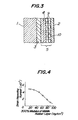
- the inventors have confirmed that the intercepting effect can be attained by providing a low modulus middle rubber layer as mentioned above by comparing crack growing speeds of test pieces as shown in Figures 2a and 2b.
- test pieces as shown in Figures 2a and 2b are respective rubber pieces 6,6' each having a length of 130 mm x a width of 25 mm x a thickness of 8 mm and a 300% modulus of 55 kg/cm 2 .
- one of the test pieces has such a sandwich structure that a middle rubber layer 7 having a thickness of 2 mm and a 300% modulus of 25 kg/cm 2 is embedded in substantially the centre of the thickness of the rubber piece 6' as shown in Figure 2b.
- Cut damage 8 is formed from the upper surface of each of the test pieces 6,6' up to a position corresponding to substantially 4 of the thickness of each test piece. Thereafter, the crack growth from the cut damage 8 is measured by subjecting the test piece to strong repeated strains under a tension force of about 20% in the lengthwise direction as shown by arrows in Figures 2a and 2b. As a result, in the test piece 6 having no low modulus middle rubber layer 7 as shown in Figure 2a, the crack growth continues toward the lower surface of the test piece and finally this piece is cut , in half at a strain repeating number of 1 x 10⁶. On the other hand, in the test piece 6' provided therein with the low modulus middle rubber layer 7 as shown in Figure 2b, the crack growth is intercepted by this middle rubber layer and does not continue beyond the rubber layer toward the lower surface of the test piece.
- the fault surface 4 or the low modulus middle rubber layer ? in the present invention is provided at the side portion of the pneumatic tire to be used for running on rough grounds, particularly near the position corresponding to maximum sectional width of the carcass layer in the side portion, especially in the case of radial tires.
- a fault surface 4 is provided outside the carcass layer 3, there is a danger of separation being caused because this portion undergoes particularly large deformation, and therefore the fault surface 4 is formed in at least one portion of the inner part of the liner layer 5 itself provided inside and adjacent to the carcass layer 3 and between the layer 5 and the carcass layer 3.
- the fault surface 4 preferably has a peeling resistant force of not more than ?.5 kg/cm, more preferably not more than 5 kg/cm, per unit breadth and when the peeling resistant force exceeds 7.5 kg/cm the effect of intercepting the crack growth may not be satisfactorily obtained.
- the 100% modulus of the rubbery elastomeric layer disposed inside and adjacent the fault surface is preferably not less than 20 kg/cm 2 , more preferably not less than 45 kg/cm 2 , to assist the prevention of crack growth.
- the liner layer 5 includes a cord reinforcing layer 9 consisting of at least one rubberized cord ply as shown in Figure 3. This is because when the tire is subjected to cut damage the circumferential strain owing to load concentrates at this cut damage portion, but the above described cord reinforcing layer 9 serves to prevent this concentration. In this case, it is preferable to locate the cord reinforcing layer inside the fault surface 4 or the low modulus middle rubber layer ? in view of the mitigation of strain concentration. In particular, when the carcass layer 3 is of radial structure, it is preferable to cross the cords in the cord reinforcing layer 9 with the cords in the carcass layer 3 at an angle of not greater than 35 0 . It will be apparent that Figure 3 shows the case where the fault surface 4 is formed in the interior of the liner layer 5, the numeral 10 indicating an inner liner.
- the fault surface 4 may be easily formed by a simple process wherein for example silicone or petroleum is applied on a bonding surface when the green case of the tire is formed.
- a low modulus middle rubber layer 7 may be provided in place of the fault surface 4.
- the middle rubber layer may be positioned at the interior of the rubber layer 19 of the side portion outside the carcass layer 3, between the rubber layer 19 of the side portion and the carcass layer 3, between the carcass layer 3 and the liner layer 5, or at the interior of the liner layer 5 itself (see Figure 6).
- the low modulus middle rubber layer may be arranged in several regions at the above positions as far as there is no problem relating to for example heat generation and rigidity balance.
- the position of the middle rubber layer 7 should be between the carcass layer 3 and the liner layer 5 or at the interior of the liner layer 5 itself.
- the separation failure of the carcass ply or plies together with air leakage caused by crack growth from the outer surface of the tire can be advantageously prevented.
- the rubber to be used in the formation of the low modulus middle rubber layer 7 preferably has a 300% modulus of not more than 50 kg/cm 2 , more preferably not more than 30 kg/cm 2 .
- the maximum value of strain in the strain concentration is about 500%, it is important that rubber used for the formation of the low modulus middle rubber layer is not broken at such a strain value. Considering this fact and further giving some allowa l thereto, it is preferable that the elongation at break of the middle rubber layer is not less than 600%.
- the difference of modulus between the rubber forming the low modulus.middle rubber layer and the rubber adjacent to the middle rubber layer is preferably not less than 20 kg/cm 2 , more preferably not less than 40 kg/cm , in the 300% modulus.
- the thickness of the low modulus middle rubber layer is preferably 0.2 to 5 mm, more preferably 2 to 3 mm.
- the thickness is less than 0.2 mm, the effect of the invention may not be sufficiently developed and also the production is difficult, while when the thickness exceeds 5 mm, the rigidity balance becomes bad, the cut damage itself is apt to be suffered and also there is a problem relating to the heat generation.
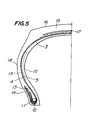
- Figure 5 shows in cross-section the left half. of a pneumatic radial tire of size 20.5 R 20 for running on rough grounds; the right half of the tire has the same structure as the left half.
- a carcass layer 3 consists of one rubberized ply containing steel cords embedded therein and arranged along the radial plane of the tire and is turned around a bead core 12 in a bead portion 11 for fitting to a rim (not shown) from the inside to the outside thereof.
- a metal chafer 13 composed of one rubberized layer containing steel cord embedded therein
- a fibre chafer 14 composed of two rubberized layers each containing nylon cords embedded, therein, the cords of which are crossed with each other, as a reinforcement.
- a belt layer 17 composed of three steel cord plies is arranged between the carcass layer 3 and the tread 16.
- an inner liner 10 is provided between both the left and right bead portions, and a liner layer 5 is disposed between the inner liner 10 and the carcass layer 3.
- the liner layer 5 is mainly composed of a rubbery elastomeric layer having a 100% modulus of 25 kg/cm2;(300/ modulus of 65 kg/cm 2 ), and provided at its inside with a cord reinforcing layer (not shown) of two cord plies extending from the bead portion 11 to the shoulder portion of the tire, the cords of which plies are crossed at an angle of 15° with respect to the radial direction of the tire.
- a fault surface 4 having an extremely low adhesion is formed at the interior of the liner layer 5 near a position corresponding to substantially the maximum sectional width of the carcass layer in the side portion of the tire.
- This fault surface 4 is formed by applying petroleum when forming the green case.
- fault surfaces having an extremely low adhesion are provided at both the left and right tire side portions but a fault surface may be formed only in one side portion.
- Figure 3 is essentially a diagrammatic view showing the arranging relation of each layer in the side portion of maximum sectional width in the embodiment of Figure 5.
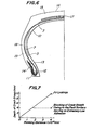
- Figure 6 shows another embodiment of a tire of the present invention wherein a low modulus middle rubber layer ? is utilized in place of the fault surface 4 in the embodiment of Figure 5.
- the size of the tire shown in Figure 6 is 20.5 R 20 and the inner structure of the tire is the same as that of the tire shown in Figure 5 except for arranging the middle rubber layer 7 in place of the fault surface 4.
- the liner layer 5 is composed of a rubbery elastomeric layer having a 300% modulus of 65 kg/cm 2 and a cord reinforcing layer (not shown) provided at the inside of the rubbery elastomeric layer, as in the case of Figure 5.
- a low modulus middle rubber layer 7 having a 300% modulus of 22 kg/cm 2 , an elongation at break of 895% and a thickness of 205 mm is arranged at the interior of the rubbery elastomeric layer of the liner layer 5 near a position corresponding to substantially the maximum sectional width of the carcass layer in the tire side portion.
- a middle rubber layer is arranged in each of the tire side portions, but may be arranged in one side portion only.
- the coating rubber for the carcass ply has a 300% modulus of 120 kg/ cm 2 .
- a durability test on a drum was made with respect to the tire as shown in Figure 5 to obtain a result as shown in Figure 7, wherein a solid line indicates the result obtained in the case of a comparative tire and a broken line indicates the result obtained in the case of the tire shown in Figure 5.
- the comparative tire has the same structure as the tire shown in Figure 5 except for the absence of the fault surface.
- cut damage was first formed in the side portion of the tire near the maximum width thereof to such a depth that the tip of the cut damage was located slightly outside the carcass layer 3, and then the depth of a crack grown from the cut damage during running of the tire was measured in a direction perpendicular to the carcass ply.
- the tire of Figure 5 is clearly superior to the comparative tire. That is, in the comparative tire having no fault surface, the crack grew with increase of the running distance and finally air leakage occurred after a running distance of about 4 x 10 3 km. On the other hand, in the tire of Figure 5, the crack growth was intercepted by the fault surface 4 and as a result no air leakage occurred even at the same running distance as described above.
Landscapes
- Engineering & Computer Science (AREA)
- Mechanical Engineering (AREA)
- Tires In General (AREA)
Applications Claiming Priority (4)
| Application Number | Priority Date | Filing Date | Title |
|---|---|---|---|
| JP55169658A JPS5795204A (en) | 1980-12-03 | 1980-12-03 | Pneumatic tire having excellent resistance to cutting |
| JP169658/80 | 1980-12-03 | ||
| JP55169659A JPS5795205A (en) | 1980-12-03 | 1980-12-03 | Pneumatic tire that prohibits growth of cut |
| JP169659/80 | 1980-12-03 |
Related Child Applications (1)
| Application Number | Title | Priority Date | Filing Date |
|---|---|---|---|
| EP85116091.1 Division-Into | 1981-12-03 |
Publications (3)
| Publication Number | Publication Date |
|---|---|
| EP0053522A2 true EP0053522A2 (de) | 1982-06-09 |
| EP0053522A3 EP0053522A3 (en) | 1983-06-08 |
| EP0053522B1 EP0053522B1 (de) | 1987-07-08 |
Family
ID=26492907
Family Applications (2)
| Application Number | Title | Priority Date | Filing Date |
|---|---|---|---|
| EP81305701A Expired EP0053522B1 (de) | 1980-12-03 | 1981-12-03 | Luftreifen |
| EP85116091A Expired - Lifetime EP0204868B1 (de) | 1980-12-03 | 1981-12-03 | Luftreifen |
Family Applications After (1)
| Application Number | Title | Priority Date | Filing Date |
|---|---|---|---|
| EP85116091A Expired - Lifetime EP0204868B1 (de) | 1980-12-03 | 1981-12-03 | Luftreifen |
Country Status (3)
| Country | Link |
|---|---|
| US (2) | US4553579A (de) |
| EP (2) | EP0053522B1 (de) |
| ES (1) | ES270021Y (de) |
Cited By (3)
| Publication number | Priority date | Publication date | Assignee | Title |
|---|---|---|---|---|
| WO1987002647A1 (fr) * | 1985-10-25 | 1987-05-07 | Imdut International B.V. | Feuille composite pour emballages |
| WO1998054012A1 (en) * | 1997-05-29 | 1998-12-03 | The Goodyear Tire & Rubber Company | An inextensible high temperature resistant runflat tire |
| CN101668647B (zh) * | 2007-04-23 | 2013-06-05 | 米其林集团总公司 | 在侧壁中包括加强件的用于车辆的轮胎 |
Families Citing this family (8)
| Publication number | Priority date | Publication date | Assignee | Title |
|---|---|---|---|---|
| JPH0782670B2 (ja) * | 1985-07-12 | 1995-09-06 | 株式会社日立製作所 | 光磁気記録媒体 |
| US5280817A (en) * | 1991-10-07 | 1994-01-25 | The Goodyear Tire & Rubber Company | Radial pneumatic tire having contoured zones in the sidewalls |
| GB9801224D0 (en) * | 1998-01-21 | 1998-03-18 | Sumitomo Rubber Ind | Improvements to tyres |
| US7028734B2 (en) * | 2003-06-24 | 2006-04-18 | The Goodyear Tire & Rubber Company | Truck tire with cap/base construction tread |
| US20110253282A1 (en) * | 2008-12-22 | 2011-10-20 | Michelin Recherche et Technique S.A. a corporation | Sidewall shear decoupling layer |
| JP5380467B2 (ja) * | 2011-01-06 | 2014-01-08 | 株式会社日立製作所 | 開閉器ユニット及びスイッチギヤ |
| BR112016023063B1 (pt) | 2014-04-03 | 2021-05-18 | Sandvik Hyperion AB | aparelho de corte rotativo para corte de uma folha contínua de material |
| WO2018034248A1 (ja) * | 2016-08-15 | 2018-02-22 | 横浜ゴム株式会社 | 空気入りタイヤ |
Family Cites Families (19)
| Publication number | Priority date | Publication date | Assignee | Title |
|---|---|---|---|---|
| CA764942A (en) * | 1967-08-08 | Du Pont Of Canada Limited | Laminated thermoplastic film having improved resistance to tear propagation | |
| US1377729A (en) * | 1919-04-23 | 1921-05-10 | William F Ray | Process of applying lubricant to tire-casings |
| US1767502A (en) * | 1928-04-13 | 1930-06-24 | Hiram C Anderson | Punctureproof pneumatic tire |
| FR1154304A (fr) * | 1956-06-27 | 1958-04-04 | Us Rubber Co | Pneumatique sans chambre à air |
| US2925846A (en) * | 1957-02-08 | 1960-02-23 | Hansford D Hurt | Multiservice protector unit for pneumatic tires and tubes |
| NL277874A (de) * | 1961-04-28 | Michelin & Cie | ||
| US3100518A (en) * | 1962-02-07 | 1963-08-13 | Dresser Richard | Pneumatic safety tire construction |
| FR1382994A (fr) * | 1963-10-03 | 1964-12-24 | Michelin & Cie | Perfectionnement aux enveloppes de pneumatiques devant résister aux perforations |
| DE1261311B (de) * | 1964-05-22 | 1968-02-15 | Huels Chemische Werke Ag | Verfahren zum Vulkanisieren von Kautschukverschnitten |
| US3306331A (en) * | 1965-06-28 | 1967-02-28 | David Ratner | Inner tube and tire valve stem protector |
| NL133000C (de) * | 1966-06-28 | |||
| FR2075851A1 (de) * | 1969-12-23 | 1971-10-15 | Michelin & Cie | |
| GB1417968A (en) * | 1971-12-11 | 1975-12-17 | Dunlop Ltd | Pneumatic tyres |
| IT963743B (it) * | 1972-08-04 | 1974-01-21 | Pirelli | Pneumatico di sicurezza in grado di esplicare sia un azione antifo ro sia un azione antiscoppio |
| US4044811A (en) * | 1975-07-16 | 1977-08-30 | The General Tire & Rubber Company | Laminated pneumatic tire |
| JPS5237642A (en) * | 1975-09-19 | 1977-03-23 | Hidemori Hayashi | Method and device for high power output wind power plant |
| JPS55110605A (en) * | 1979-02-19 | 1980-08-26 | Bridgestone Corp | Pneumatic bicycle tire having good high-speed stability |
| JPS5851601Y2 (ja) * | 1979-12-29 | 1983-11-24 | 株式会社ブリヂストン | 荒地走行用空気入りバイアスタイヤ |
| JPS5925683Y2 (ja) * | 1980-02-25 | 1984-07-27 | 株式会社ブリヂストン | 重荷重用空気入りラジアルタイヤ |
-
1981
- 1981-12-01 ES ES1981270021U patent/ES270021Y/es not_active Expired
- 1981-12-03 EP EP81305701A patent/EP0053522B1/de not_active Expired
- 1981-12-03 EP EP85116091A patent/EP0204868B1/de not_active Expired - Lifetime
-
1984
- 1984-06-07 US US06/618,752 patent/US4553579A/en not_active Expired - Fee Related
- 1984-09-24 US US06/654,051 patent/US4569381A/en not_active Expired - Fee Related
Cited By (5)
| Publication number | Priority date | Publication date | Assignee | Title |
|---|---|---|---|---|
| WO1987002647A1 (fr) * | 1985-10-25 | 1987-05-07 | Imdut International B.V. | Feuille composite pour emballages |
| WO1998054012A1 (en) * | 1997-05-29 | 1998-12-03 | The Goodyear Tire & Rubber Company | An inextensible high temperature resistant runflat tire |
| US6026878A (en) * | 1997-05-29 | 2000-02-22 | The Goodyear Tire & Rubber Company | Inextensible high temperature resistant tire |
| AU721711B2 (en) * | 1997-05-29 | 2000-07-13 | Goodyear Tire And Rubber Company, The | An inextensible high temperature resistant runflat tire |
| CN101668647B (zh) * | 2007-04-23 | 2013-06-05 | 米其林集团总公司 | 在侧壁中包括加强件的用于车辆的轮胎 |
Also Published As
| Publication number | Publication date |
|---|---|
| ES270021U (es) | 1983-07-16 |
| EP0204868A2 (de) | 1986-12-17 |
| EP0204868B1 (de) | 1991-09-18 |
| EP0053522B1 (de) | 1987-07-08 |
| US4569381A (en) | 1986-02-11 |
| EP0204868A3 (en) | 1987-05-20 |
| EP0053522A3 (en) | 1983-06-08 |
| US4553579A (en) | 1985-11-19 |
| ES270021Y (es) | 1984-02-01 |
Similar Documents
| Publication | Publication Date | Title |
|---|---|---|
| US3964533A (en) | Pneumatic radial type tire having an improved durability in bead section | |
| CA1234340A (en) | Pneumatic tire | |
| US5709760A (en) | Thin gauge, fine diameter steel cord reinforced tire ply fabric which is lap spliced | |
| US4047552A (en) | Pneumatic radial tire for heavy load vehicles | |
| EP0143651A2 (de) | Radial-Luftreifen | |
| US4077454A (en) | Pneumatic tires suitable for off-road vehicles | |
| EP0204868B1 (de) | Luftreifen | |
| US4446905A (en) | Radial tires for running on rough ground | |
| US5176769A (en) | Radial tire for aircraft including both a circumferential breaker ply and an intersecting breaker ply | |
| US5711829A (en) | Three- belt tire | |
| US6976518B2 (en) | Pneumatic radial tires | |
| US4733708A (en) | Use of flat wire as a reinforcement in the belt package of a pneumatic tire | |
| US7093634B2 (en) | Two piece tire with improved tire tread belt | |
| JPH05310013A (ja) | ランフラット空気入りラジアルタイヤ | |
| CN1239918A (zh) | 轮胎的胎冠加强件 | |
| US6615889B1 (en) | Heavy duty radial tire | |
| US3999586A (en) | Reinforcing belt for a pneumatic tire | |
| JP3817372B2 (ja) | 建設車両用空気入りラジアルタイヤ | |
| JPH07186614A (ja) | 空気入りラジアルタイヤ | |
| JP2955774B2 (ja) | 重荷重用空気入りラジアルタイヤ | |
| JPH07137155A (ja) | ラジアルタイヤ貫通傷の修理方法及び修理パッチ | |
| EP0659595B1 (de) | Radialer Luftreifen | |
| JPH03200403A (ja) | 荒地走行重車両用ラジアルタイヤ | |
| JP3553663B2 (ja) | 建設車両用空気入りラジアルタイヤ | |
| JP2001030709A (ja) | 重荷重用ラジアルタイヤ |
Legal Events
| Date | Code | Title | Description |
|---|---|---|---|
| PUAI | Public reference made under article 153(3) epc to a published international application that has entered the european phase |
Free format text: ORIGINAL CODE: 0009012 |
|
| AK | Designated contracting states |
Designated state(s): FR GB SE |
|
| PUAL | Search report despatched |
Free format text: ORIGINAL CODE: 0009013 |
|
| AK | Designated contracting states |
Designated state(s): FR GB SE |
|
| 17P | Request for examination filed |
Effective date: 19831122 |
|
| GRAA | (expected) grant |
Free format text: ORIGINAL CODE: 0009210 |
|
| AK | Designated contracting states |
Kind code of ref document: B1 Designated state(s): FR GB SE |
|
| ET | Fr: translation filed | ||
| PLBE | No opposition filed within time limit |
Free format text: ORIGINAL CODE: 0009261 |
|
| STAA | Information on the status of an ep patent application or granted ep patent |
Free format text: STATUS: NO OPPOSITION FILED WITHIN TIME LIMIT |
|
| 26N | No opposition filed | ||
| PGFP | Annual fee paid to national office [announced via postgrant information from national office to epo] |
Ref country code: GB Payment date: 19931123 Year of fee payment: 13 |
|
| PGFP | Annual fee paid to national office [announced via postgrant information from national office to epo] |
Ref country code: SE Payment date: 19931215 Year of fee payment: 13 |
|
| PG25 | Lapsed in a contracting state [announced via postgrant information from national office to epo] |
Ref country code: GB Effective date: 19941203 |
|
| PG25 | Lapsed in a contracting state [announced via postgrant information from national office to epo] |
Ref country code: SE Effective date: 19941204 |
|
| PGFP | Annual fee paid to national office [announced via postgrant information from national office to epo] |
Ref country code: FR Payment date: 19941209 Year of fee payment: 14 |
|
| EAL | Se: european patent in force in sweden |
Ref document number: 81305701.5 |
|
| GBPC | Gb: european patent ceased through non-payment of renewal fee |
Effective date: 19941203 |
|
| EUG | Se: european patent has lapsed |
Ref document number: 81305701.5 |
|
| PG25 | Lapsed in a contracting state [announced via postgrant information from national office to epo] |
Ref country code: FR Effective date: 19960830 |
|
| REG | Reference to a national code |
Ref country code: FR Ref legal event code: ST |