EP0363738B1 - Capteur en effet Hall et circuit magnétique pour un tel capteur - Google Patents
Capteur en effet Hall et circuit magnétique pour un tel capteur Download PDFInfo
- Publication number
- EP0363738B1 EP0363738B1 EP89117911A EP89117911A EP0363738B1 EP 0363738 B1 EP0363738 B1 EP 0363738B1 EP 89117911 A EP89117911 A EP 89117911A EP 89117911 A EP89117911 A EP 89117911A EP 0363738 B1 EP0363738 B1 EP 0363738B1
- Authority
- EP
- European Patent Office
- Prior art keywords
- magnetic flux
- hall
- flux guide
- hall effect
- effect type
- Prior art date
- Legal status (The legal status is an assumption and is not a legal conclusion. Google has not performed a legal analysis and makes no representation as to the accuracy of the status listed.)
- Expired - Lifetime
Links
Images


Classifications
-
- G—PHYSICS
- G01—MEASURING; TESTING
- G01D—MEASURING NOT SPECIALLY ADAPTED FOR A SPECIFIC VARIABLE; ARRANGEMENTS FOR MEASURING TWO OR MORE VARIABLES NOT COVERED IN A SINGLE OTHER SUBCLASS; TARIFF METERING APPARATUS; MEASURING OR TESTING NOT OTHERWISE PROVIDED FOR
- G01D5/00—Mechanical means for transferring the output of a sensing member; Means for converting the output of a sensing member to another variable where the form or nature of the sensing member does not constrain the means for converting; Transducers not specially adapted for a specific variable
- G01D5/12—Mechanical means for transferring the output of a sensing member; Means for converting the output of a sensing member to another variable where the form or nature of the sensing member does not constrain the means for converting; Transducers not specially adapted for a specific variable using electric or magnetic means
- G01D5/14—Mechanical means for transferring the output of a sensing member; Means for converting the output of a sensing member to another variable where the form or nature of the sensing member does not constrain the means for converting; Transducers not specially adapted for a specific variable using electric or magnetic means influencing the magnitude of a current or voltage
- G01D5/142—Mechanical means for transferring the output of a sensing member; Means for converting the output of a sensing member to another variable where the form or nature of the sensing member does not constrain the means for converting; Transducers not specially adapted for a specific variable using electric or magnetic means influencing the magnitude of a current or voltage using Hall-effect devices
- G01D5/147—Mechanical means for transferring the output of a sensing member; Means for converting the output of a sensing member to another variable where the form or nature of the sensing member does not constrain the means for converting; Transducers not specially adapted for a specific variable using electric or magnetic means influencing the magnitude of a current or voltage using Hall-effect devices influenced by the movement of a third element, the position of Hall device and the source of magnetic field being fixed in respect to each other
Definitions
- the present invention relates to a Hall effect type sensing device according to the first part of claim 1.
- sensing device such as a position sensor, an angle sensor, a speed sensor and so on which utilize Hall effect.
- a Hall IC formed by integrating and packaging Hall transducing elements used for such sensing device has also been known.
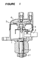
- a reference numeral 1 designates a housing as an element of a distributor
- a numeral 2 designates a shaft which is inserted in the central portion of the housing 1 so as to be freely rotable.
- the shaft 2 is connected to, for instance, a cam shaft (not shown) in an internal combustion engine through a coupling 21 and is driven in synchronism with the rotation of the engine.
- a numeral 3 designates a magnetic flux shutter of a magnetic material connected to the shaft 2 so as to be rotatable therewith
- a numeral 4 designates a Hall effect type sensing device connected to the housing 1
- a numeral 5 designates a rotor for the distributor attached to an end of the shaft 2 so as to be rotatable therewith
- a numeral 6 designates a cap for the distributor.
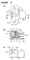
- the Hall effect type sensing device 4 comprises a frame 40, a holder 44 for supporting a Hall IC 41, a magnetic flux guide 42a and a plate 43 made of a non-magnetic material such as stainless steel, an another magnetic flux guide 42b and a magnet 45 attached to the magnetic flux guide 42b.
- the holder 44 is formed of a resinous material by molding and has a second holding block 40A in a generally channel-like form in which a pair of grooves 40a are formed in the vertical direction of the opposing inner side surfaces of the channel-like holding block 40A, a first holding block 40B which consists of two rectangular prism-like pieces each having a vertical groove 40b facing to each other, a connecting portion 40c and connecting conductors 40d, which are integrally formed with the frame 40. An end portion of each of the connecting conductors 40d is exposed in the connecting portion 40c to form a conneting pin so that it is electrically connectable to an outer circuit, and the other end portion of them is connected to each lead wire 41a at an exposing portion A by welding as shown in Figure 2b.
- the holder 44 is also formed by molding a resinous material and has a pair of vertically extending projections 44a to be engaged with the grooves 40a of the frame 40, a first recessed portion 44b for receiving and holding the Hall IC 41, a second recessed portion 44c formed in the first recessed portion 44b so as to extend in the vertical direction so that the magnetic flux guide 42a is received, and four projections 44d extending laterally to support the plate 43.
- Plate 43 is provided with through holes 43a to be fitted to the four projections 44d of the holder 44.
- the magnetic flux guide 42b is provided with a pair of vertically extending projections 42ba which are to be fitted to the grooves 40b formed in the first holding block 40B of the frame 40.
- the Hall IC 41, the magnetic flux guide 42a and the plate 43 are fitted to the holder 44, and then, the holder 44 is assembled to the frame 40 by fitting the projections 44a to the grooves 40a.
- the magnetic flux guide 42b is also fitted to the frame 40 by fitting the projections 42ba to the grooves 40b.
- the plate 43 functions as a dam to prevent the resin from overflowing.
- a sufficient air gap G is provided between the magnetic flux guides 42a, 42b and between the magnet 45 and the plate 43 so as to pass the magnetic flux shutter 3.
- the magnetic flux shutter 3 integrally attached to the shaft 2 is also rotated so as to move in the magnetic circuit including the Hall IC 41.
- the magnetic flux shutter 3 has its circumferential portion formed in a cascade form although omitted in the figures. Accordingly, a change of magnetic flux depending on the revolution speed of the shaft 2 can be given to the Hall IC 41.
- the Hall IC 41 converts the change of magnetic flux into an electric signal corresponding to the revolution of the internal combustion engine, which is taken through the connecting portion 40c.
- a processing circuit not shown
- a crank angle is detected, whereby ignition timing can be controlled.
- the positions of the Hall IC 41, the magnetic flux guide 42a and so on to the frame 40 are determined by means of the holder 44.
- these elements may be directly supported by the frame 40 without using the holder 44.
- the frame 40 may be of a container-like body or may be a container itself. Further, the shape and the number of the holding blocks 40a, 40b, the grooves 40a, 40b and the way of splitting the magnetic flux guides and the position of the magnet are not limited to the above-mentioned embodiment.
- the magnetic flux shutter 3 may be of a linearly movable type.
- a Hall effect type sensing device capable of facilitating position-determining, generating accurate signals and adopting an automatic system can be obtained.
- Figures 4 and 5 show another embodiment of the Hall effect type sensing device according to the present invention.
- the same reference numerals designate the same part as in the first embodiment, and therefore, description of these parts is omitted.
- a magnetic circuit device 7 comprises a magnet 71, a first magnetic flux guide 72 and a second magnetic flux guide 73.
- a recess 73a is formed in the second magnetic flux guide 73 so as to determine the position of the magnet 71, and the magnet 71 is firmly connected to the recess 73a by bonding.
- the first magnetic flux guide 72 is to be received in the recess 44c formed in the holder 44 which is the same as the first embodiment.
- the second magnetic flux guide 73 is provided with a pair of extensions 73b which are to be fitted to the grooves 40b of the frame 40 which are the same as the first embodiment.
- the magnetic circuit device 7 is fitted to the frame 40 by engaging the pair of extensions 73b of the second magnetic flux guide 73 with the pair of grooves 40b of the frame 40 after the magnet 71 has been attached to the recess 73a of the second magnetic flux guide 73 with an adhesive. Further, as shown in Figures 4 and 5, the holder 44 is fitted to the frame 40 by engaging the two extensions 44a with the grooves 40a of the holder after the Hall IC 41, the first magnetic flux guide 72 and the plate 43 have been assembled to the holder 44. Thus, the structural elements of the sensing device can be correctly positioned and firmly supported by the frame 40. Then, lead wires 41a are electrically connected to the connecting conductors 40d by, for instance, spot welding. A thermosetting resin is injected in a space S around the Hall IC 41 so that the Hall IC 41 becomes immovable by curing the resin.
- Figure 6 is a cross-sectional view of the second magnetic guide 73 and the magnet 71 as another embodiment of the present invention.
- the surface area of the bottom wall portion of the recess 73a is made large so that an effective bonding surface to the magnet 71 is increased.
- an adhesive 8 is applied to the side wall portion 73c as well as the bottom wall portion of the recess 73a.
- position-determining and fixing the magnet 71 become further reliable.
- the inner surface of the recess 73a has a rough surface in order to strongly bond the magnet 71.
- the magnet 71 can be easily attached to the magnetic flux guide at a correct position.
- a Hall effect type sensor capable of providing accurate signals can be obtained.
- an automatic manufacturing system can be easily adopted because the positioning of the structural elements of the sensing device can be easy.
Landscapes
- Physics & Mathematics (AREA)
- General Physics & Mathematics (AREA)
- Transmission And Conversion Of Sensor Element Output (AREA)
- Measuring Magnetic Variables (AREA)
- Ignition Installations For Internal Combustion Engines (AREA)
Claims (5)
- Dispositif de détection du type à effet Hall, comprenant un aimant (45; 71) et un dispositif de guidage de flux magnétique (42a, 42b; 72, 73) qui coopèrent pour former un circuit magnétique, et un circuit intégré à effet Hall (41) disposé dans le circuit magnétique, lesdits éléments étant assujettis à un bâti (40), caractérisé en ce que ledit bâti (40) supporte un dispositif de maintien (44) qui maintient une partie (42a; 72) dudit dispositif de guidage de flux magnétique et ledit circuit intégré à effet Hall (41) dans des positions déterminées et auquel est assujettie une plaque (43) destinée à recouvrir ledit circuit intégré à effet Hall, et en ce qu'une autre partie (42b; 73) dudit dispositif de guidage de glux magnétique est maintenu directement dans une position déterminée au niveau dudit bâti (40).
- Dispositif selon la revendication 1, caractérisé en ce que ledit bâti (40) est réalisé en une matière de résine formée par moulage et est pourvu, faisant partie intégrante de lui, d'un premier bloc de maintien (40B) destiné à maintenir ladite autre partie (42b; 73) dudit dispositif de guidage de flux magnétique (42a, 42b; 72, 73), et d'un second bloc de maintien (40A) destiné à maintenir ledit dispositif de maintien (44) dans lequel ledit circuit intégré à effet Hall (41) et ladite partie (42a; 72) dudit dispositif de guidage de flux magnétique sont supportés.
- Dispositif selon la revendication 2, caractérisé en ce que l'autre partie (42b; 73) dudit dispositif de guidage de flux magnétique et ledit dispositif de maintien (44) sont maintenus respectivement par lesdits premier et second bloc de maintien (40B, 40A) à l'aide de paires de saillies et de rainures respectives (40a, 40b).
- Dispositif selon l'une des revendications 1 à 3, caractérisé en ce que ladite autre partie (42b; 73) dudit dispositif de guidage de flux magnétique comporte un évidement (73a) et ledit aimant (71) est assujetti fermement par adhésion audit évidement.
- Dispositif selon la revendication 4, caractérisé en ce que la superficie de la partie formant paroi de fond dudit évidement (73a) est agrandie de sorte qu'une surface efficace d'adhésion avec ledit aimant (71) soit augmentée.
Applications Claiming Priority (6)
| Application Number | Priority Date | Filing Date | Title |
|---|---|---|---|
| JP131723/88U | 1988-10-11 | ||
| JP1988131723U JP2525436Y2 (ja) | 1988-10-11 | 1988-10-11 | ホール効果型センサの磁気回路装置 |
| JP131724/88U | 1988-10-11 | ||
| JP13172288U JPH0252104U (fr) | 1988-10-11 | 1988-10-11 | |
| JP131722/88U | 1988-10-11 | ||
| JP1988131724U JP2525437Y2 (ja) | 1988-10-11 | 1988-10-11 | ホール効果型センサ装置 |
Publications (3)
| Publication Number | Publication Date |
|---|---|
| EP0363738A2 EP0363738A2 (fr) | 1990-04-18 |
| EP0363738A3 EP0363738A3 (en) | 1990-08-29 |
| EP0363738B1 true EP0363738B1 (fr) | 1992-12-09 |
Family
ID=27316358
Family Applications (1)
| Application Number | Title | Priority Date | Filing Date |
|---|---|---|---|
| EP89117911A Expired - Lifetime EP0363738B1 (fr) | 1988-10-11 | 1989-09-28 | Capteur en effet Hall et circuit magnétique pour un tel capteur |
Country Status (5)
| Country | Link |
|---|---|
| US (1) | US5028868A (fr) |
| EP (1) | EP0363738B1 (fr) |
| KR (1) | KR930004094Y1 (fr) |
| DE (1) | DE68903824T2 (fr) |
| HK (1) | HK1000734A1 (fr) |
Cited By (1)
| Publication number | Priority date | Publication date | Assignee | Title |
|---|---|---|---|---|
| US6016055A (en) * | 1995-02-02 | 2000-01-18 | Siemens Aktiengesellschaft | Device for increasing the magnetic flux density in the vicinity of a hall sensor cooperating with a magnet wheel |
Families Citing this family (67)
| Publication number | Priority date | Publication date | Assignee | Title |
|---|---|---|---|---|
| DE8814267U1 (de) * | 1988-11-15 | 1990-03-29 | Robert Bosch Gmbh, 7000 Stuttgart | Zündverteiler für Brennkraftmaschinen |
| JPH0489506A (ja) * | 1990-08-02 | 1992-03-23 | Mitsubishi Electric Corp | 角度検出装置 |
| US5351670A (en) * | 1991-11-21 | 1994-10-04 | Nippondenso Co., Ltd. | Ignition distributor for an internal combustion engine |
| DE4141958A1 (de) * | 1991-12-19 | 1993-06-24 | Swf Auto Electric Gmbh | Drehzahlsensor, insbesondere zahnradsensor |
| US6198275B1 (en) | 1995-06-07 | 2001-03-06 | American Electronic Components | Electronic circuit for automatic DC offset compensation for a linear displacement sensor |
| US5332965A (en) * | 1992-06-22 | 1994-07-26 | Durakool Incorporated | Contactless linear angular position sensor having an adjustable flux concentrator for sensitivity adjustment and temperature compensation |
| US5757181A (en) * | 1992-06-22 | 1998-05-26 | Durakool Incorporated | Electronic circuit for automatically compensating for errors in a sensor with an analog output signal |
| DE4323012C2 (de) * | 1992-07-10 | 1996-08-29 | Mitsubishi Electric Corp | Vorrichtung für eine Brennkraftmaschine zur Erfassung des Kurbelwellenwinkels |
| FR2707392B1 (fr) * | 1993-07-05 | 1995-08-11 | Siemens Automotive Sa | Capteur de position angulaire à effet hall. |
| US5406926A (en) * | 1993-08-31 | 1995-04-18 | Industrial Technology Research Institute | Signal generator for an internal combustion engine |
| JPH08254172A (ja) * | 1995-03-17 | 1996-10-01 | Mitsubishi Electric Corp | 回転角度検出装置 |
| US5613571A (en) * | 1995-09-26 | 1997-03-25 | Harley-Davidson, Inc. | Rotational speed/tip sensor |
| US6201388B1 (en) | 1997-11-10 | 2001-03-13 | Invensys Building Systems, Inc. | Device for determining the angular position of a rotating member utilizing a magnetic hall effect transducer |
| US6285958B1 (en) | 1998-02-12 | 2001-09-04 | American Electronic Components, Inc. | Electronic circuit for automatic compensation of a sensor output signal |
| JP3532778B2 (ja) * | 1998-05-15 | 2004-05-31 | 株式会社東海理化電機製作所 | 回転検出センサ |
| US6050242A (en) * | 1998-10-21 | 2000-04-18 | Pertronix, Inc. | Lobe sensor arrangement for an ignition system |
| US6094912A (en) * | 1999-02-12 | 2000-08-01 | Stirling Technology Company | Apparatus and method for adaptively controlling moving members within a closed cycle thermal regenerative machine |
| KR100310115B1 (ko) * | 1999-07-22 | 2001-11-01 | 반갑수 | 자동차 샤시 용접용 센싱장치 |
| US6703827B1 (en) | 2000-06-22 | 2004-03-09 | American Electronics Components, Inc. | Electronic circuit for automatic DC offset compensation for a linear displacement sensor |
| US6752134B1 (en) | 2001-02-15 | 2004-06-22 | Pertronix, Inc. | Ignition arrangement |
| US6609507B2 (en) | 2001-08-20 | 2003-08-26 | Pertronix, Inc. | Second strike ignition system |
| JP4118552B2 (ja) | 2001-12-05 | 2008-07-16 | アイシン精機株式会社 | 電子部品の保持構造及び電子部品の保持方法 |
| US7816772B2 (en) * | 2007-03-29 | 2010-10-19 | Allegro Microsystems, Inc. | Methods and apparatus for multi-stage molding of integrated circuit package |
| US9823090B2 (en) | 2014-10-31 | 2017-11-21 | Allegro Microsystems, Llc | Magnetic field sensor for sensing a movement of a target object |
| US8486755B2 (en) * | 2008-12-05 | 2013-07-16 | Allegro Microsystems, Llc | Magnetic field sensors and methods for fabricating the magnetic field sensors |
| US20100188078A1 (en) * | 2009-01-28 | 2010-07-29 | Andrea Foletto | Magnetic sensor with concentrator for increased sensing range |
| US8629539B2 (en) | 2012-01-16 | 2014-01-14 | Allegro Microsystems, Llc | Methods and apparatus for magnetic sensor having non-conductive die paddle |
| US9494660B2 (en) | 2012-03-20 | 2016-11-15 | Allegro Microsystems, Llc | Integrated circuit package having a split lead frame |
| US9812588B2 (en) | 2012-03-20 | 2017-11-07 | Allegro Microsystems, Llc | Magnetic field sensor integrated circuit with integral ferromagnetic material |
| US9666788B2 (en) | 2012-03-20 | 2017-05-30 | Allegro Microsystems, Llc | Integrated circuit package having a split lead frame |
| US10234513B2 (en) | 2012-03-20 | 2019-03-19 | Allegro Microsystems, Llc | Magnetic field sensor integrated circuit with integral ferromagnetic material |
| US10215550B2 (en) | 2012-05-01 | 2019-02-26 | Allegro Microsystems, Llc | Methods and apparatus for magnetic sensors having highly uniform magnetic fields |
| US9817078B2 (en) | 2012-05-10 | 2017-11-14 | Allegro Microsystems Llc | Methods and apparatus for magnetic sensor having integrated coil |
| US9213072B2 (en) * | 2012-06-08 | 2015-12-15 | General Electric Company | Radio-frequency traps and methods of common-mode energy damping |
| US10725100B2 (en) | 2013-03-15 | 2020-07-28 | Allegro Microsystems, Llc | Methods and apparatus for magnetic sensor having an externally accessible coil |
| US9411025B2 (en) | 2013-04-26 | 2016-08-09 | Allegro Microsystems, Llc | Integrated circuit package having a split lead frame and a magnet |
| US10495699B2 (en) | 2013-07-19 | 2019-12-03 | Allegro Microsystems, Llc | Methods and apparatus for magnetic sensor having an integrated coil or magnet to detect a non-ferromagnetic target |
| US9810519B2 (en) | 2013-07-19 | 2017-11-07 | Allegro Microsystems, Llc | Arrangements for magnetic field sensors that act as tooth detectors |
| US10145908B2 (en) | 2013-07-19 | 2018-12-04 | Allegro Microsystems, Llc | Method and apparatus for magnetic sensor producing a changing magnetic field |
| DE102014013356A1 (de) * | 2014-09-08 | 2016-03-10 | Wabco Gmbh | Träger für ein Sensorelement, Bauteilgruppe und Drehzahlsensor |
| US9823092B2 (en) | 2014-10-31 | 2017-11-21 | Allegro Microsystems, Llc | Magnetic field sensor providing a movement detector |
| US9719806B2 (en) | 2014-10-31 | 2017-08-01 | Allegro Microsystems, Llc | Magnetic field sensor for sensing a movement of a ferromagnetic target object |
| US9720054B2 (en) | 2014-10-31 | 2017-08-01 | Allegro Microsystems, Llc | Magnetic field sensor and electronic circuit that pass amplifier current through a magnetoresistance element |
| US10712403B2 (en) | 2014-10-31 | 2020-07-14 | Allegro Microsystems, Llc | Magnetic field sensor and electronic circuit that pass amplifier current through a magnetoresistance element |
| US10260905B2 (en) | 2016-06-08 | 2019-04-16 | Allegro Microsystems, Llc | Arrangements for magnetic field sensors to cancel offset variations |
| US10041810B2 (en) | 2016-06-08 | 2018-08-07 | Allegro Microsystems, Llc | Arrangements for magnetic field sensors that act as movement detectors |
| US10012518B2 (en) | 2016-06-08 | 2018-07-03 | Allegro Microsystems, Llc | Magnetic field sensor for sensing a proximity of an object |
| AT519206B1 (de) * | 2016-09-19 | 2019-02-15 | Avl Ditest Gmbh | Vorrichtung zur Positionsbestimmung und/oder Verstellung zumindest einer Welle einer Brennkraftmaschine |
| US11428755B2 (en) | 2017-05-26 | 2022-08-30 | Allegro Microsystems, Llc | Coil actuated sensor with sensitivity detection |
| US10837943B2 (en) | 2017-05-26 | 2020-11-17 | Allegro Microsystems, Llc | Magnetic field sensor with error calculation |
| US10996289B2 (en) | 2017-05-26 | 2021-05-04 | Allegro Microsystems, Llc | Coil actuated position sensor with reflected magnetic field |
| US10324141B2 (en) | 2017-05-26 | 2019-06-18 | Allegro Microsystems, Llc | Packages for coil actuated position sensors |
| US10641842B2 (en) | 2017-05-26 | 2020-05-05 | Allegro Microsystems, Llc | Targets for coil actuated position sensors |
| US10310028B2 (en) | 2017-05-26 | 2019-06-04 | Allegro Microsystems, Llc | Coil actuated pressure sensor |
| US10866117B2 (en) | 2018-03-01 | 2020-12-15 | Allegro Microsystems, Llc | Magnetic field influence during rotation movement of magnetic target |
| US11255700B2 (en) | 2018-08-06 | 2022-02-22 | Allegro Microsystems, Llc | Magnetic field sensor |
| US10921391B2 (en) | 2018-08-06 | 2021-02-16 | Allegro Microsystems, Llc | Magnetic field sensor with spacer |
| US10823586B2 (en) | 2018-12-26 | 2020-11-03 | Allegro Microsystems, Llc | Magnetic field sensor having unequally spaced magnetic field sensing elements |
| US11061084B2 (en) | 2019-03-07 | 2021-07-13 | Allegro Microsystems, Llc | Coil actuated pressure sensor and deflectable substrate |
| US10955306B2 (en) | 2019-04-22 | 2021-03-23 | Allegro Microsystems, Llc | Coil actuated pressure sensor and deformable substrate |
| US10991644B2 (en) | 2019-08-22 | 2021-04-27 | Allegro Microsystems, Llc | Integrated circuit package having a low profile |
| JP7018045B2 (ja) * | 2019-09-06 | 2022-02-09 | ジェコー株式会社 | アクチュエータ及び排気バルブ駆動装置 |
| US11237020B2 (en) | 2019-11-14 | 2022-02-01 | Allegro Microsystems, Llc | Magnetic field sensor having two rows of magnetic field sensing elements for measuring an angle of rotation of a magnet |
| US11280637B2 (en) | 2019-11-14 | 2022-03-22 | Allegro Microsystems, Llc | High performance magnetic angle sensor |
| US11262422B2 (en) | 2020-05-08 | 2022-03-01 | Allegro Microsystems, Llc | Stray-field-immune coil-activated position sensor |
| US11493361B2 (en) | 2021-02-26 | 2022-11-08 | Allegro Microsystems, Llc | Stray field immune coil-activated sensor |
| US11578997B1 (en) | 2021-08-24 | 2023-02-14 | Allegro Microsystems, Llc | Angle sensor using eddy currents |
Family Cites Families (6)
| Publication number | Priority date | Publication date | Assignee | Title |
|---|---|---|---|---|
| US4165726A (en) * | 1977-10-05 | 1979-08-28 | Chrysler Corporation | Low mass breakerless ignition distributor |
| US4235213A (en) * | 1978-09-14 | 1980-11-25 | Motorola, Inc. | Hall effect ignition system housing |
| DE2935412A1 (de) * | 1979-09-01 | 1981-03-19 | Robert Bosch Gmbh, 7000 Stuttgart | Kontaktlos gesteuerte spulenzuendanlage fuer brennkraftmaschinen |
| DE3018787A1 (de) * | 1980-05-16 | 1981-11-26 | Robert Bosch Gmbh, 7000 Stuttgart | Kontaktlos gesteuerte spulenzuendanlage fuer brennkraftmaschinen |
| DE3138390A1 (de) * | 1981-09-26 | 1983-04-07 | Robert Bosch Gmbh, 7000 Stuttgart | Zuendverteiler fuer brennkraftmaschinen |
| US4677946A (en) * | 1985-05-30 | 1987-07-07 | Ford Motor Company | Apparatus for positioning two sensor devices |
-
1989
- 1989-09-21 KR KR2019890013754U patent/KR930004094Y1/ko not_active Application Discontinuation
- 1989-09-28 EP EP89117911A patent/EP0363738B1/fr not_active Expired - Lifetime
- 1989-09-28 US US07/413,648 patent/US5028868A/en not_active Expired - Lifetime
- 1989-09-28 DE DE8989117911T patent/DE68903824T2/de not_active Expired - Fee Related
-
1997
- 1997-12-01 HK HK97102287A patent/HK1000734A1/xx not_active IP Right Cessation
Cited By (1)
| Publication number | Priority date | Publication date | Assignee | Title |
|---|---|---|---|---|
| US6016055A (en) * | 1995-02-02 | 2000-01-18 | Siemens Aktiengesellschaft | Device for increasing the magnetic flux density in the vicinity of a hall sensor cooperating with a magnet wheel |
Also Published As
| Publication number | Publication date |
|---|---|
| EP0363738A3 (en) | 1990-08-29 |
| US5028868A (en) | 1991-07-02 |
| DE68903824T2 (de) | 1993-06-24 |
| DE68903824D1 (de) | 1993-01-21 |
| HK1000734A1 (en) | 1998-04-24 |
| KR930004094Y1 (ko) | 1993-06-30 |
| KR900008800U (ko) | 1990-05-03 |
| EP0363738A2 (fr) | 1990-04-18 |
Similar Documents
| Publication | Publication Date | Title |
|---|---|---|
| EP0363738B1 (fr) | Capteur en effet Hall et circuit magnétique pour un tel capteur | |
| US5729128A (en) | Magnetic sensor with a magnetically sensitive component that is movable during calibration and rigidly attachable to a formed magnet | |
| US5010263A (en) | Hall effect type sensing device | |
| US5137677A (en) | Hall sensor device and method of producing the same | |
| KR930006096B1 (ko) | 호올 효과형 센서 장치 | |
| US5659246A (en) | Magnetic sensor having an engaging portion | |
| EP1120626B1 (fr) | Appareil de mesure de la position angulaire | |
| KR101503935B1 (ko) | 각도 센서를 구비한 장착 부재를 제조하는 방법 | |
| US5237272A (en) | Magnetic circuit device for a hall effect type sensor for detecting crank angle | |
| US7049807B2 (en) | Rotation detection device with magnet magnetized after intergration with gear | |
| US11131593B2 (en) | Sensor device | |
| US5278497A (en) | Magnetic sensor having a magnet-sensitive plane of an MR element arranged perpendicular to both a substrate plane and a magnet | |
| JPH11153452A (ja) | 回転検出装置 | |
| US5138258A (en) | Hall effect device for crank angle sensing in which the hall effect device is sealed in a frame using silicone gel and resin | |
| JP2004294070A (ja) | 磁気検出装置の製造方法 | |
| JPH02284082A (ja) | ホール効果型センサ装置 | |
| JPH02188634A (ja) | 移動検出装置 | |
| JP2542691B2 (ja) | ホ―ル効果形センサ装置 | |
| JP2525436Y2 (ja) | ホール効果型センサの磁気回路装置 | |
| JPH02240585A (ja) | ホール効果型センサ装置 | |
| JP2525437Y2 (ja) | ホール効果型センサ装置 | |
| EP0030079B1 (fr) | Appareil pour positionner le capteur d'un générateur de signal sans contact | |
| US20240122658A1 (en) | Control circuit and motor assembly for surgical handpiece | |
| JPH102757A (ja) | 変位センサ | |
| JPH0736291Y2 (ja) | 電磁型移動状態検出装置 |
Legal Events
| Date | Code | Title | Description |
|---|---|---|---|
| PUAI | Public reference made under article 153(3) epc to a published international application that has entered the european phase |
Free format text: ORIGINAL CODE: 0009012 |
|
| AK | Designated contracting states |
Kind code of ref document: A2 Designated state(s): DE FR GB |
|
| PUAL | Search report despatched |
Free format text: ORIGINAL CODE: 0009013 |
|
| AK | Designated contracting states |
Kind code of ref document: A3 Designated state(s): DE FR GB |
|
| 17P | Request for examination filed |
Effective date: 19901128 |
|
| 17Q | First examination report despatched |
Effective date: 19910808 |
|
| GRAA | (expected) grant |
Free format text: ORIGINAL CODE: 0009210 |
|
| AK | Designated contracting states |
Kind code of ref document: B1 Designated state(s): DE FR GB |
|
| REF | Corresponds to: |
Ref document number: 68903824 Country of ref document: DE Date of ref document: 19930121 |
|
| ET | Fr: translation filed | ||
| PLBE | No opposition filed within time limit |
Free format text: ORIGINAL CODE: 0009261 |
|
| STAA | Information on the status of an ep patent application or granted ep patent |
Free format text: STATUS: NO OPPOSITION FILED WITHIN TIME LIMIT |
|
| 26N | No opposition filed | ||
| REG | Reference to a national code |
Ref country code: GB Ref legal event code: IF02 |
|
| PGFP | Annual fee paid to national office [announced via postgrant information from national office to epo] |
Ref country code: FR Payment date: 20020910 Year of fee payment: 14 |
|
| PGFP | Annual fee paid to national office [announced via postgrant information from national office to epo] |
Ref country code: GB Payment date: 20020925 Year of fee payment: 14 |
|
| PGFP | Annual fee paid to national office [announced via postgrant information from national office to epo] |
Ref country code: DE Payment date: 20021002 Year of fee payment: 14 |
|
| PG25 | Lapsed in a contracting state [announced via postgrant information from national office to epo] |
Ref country code: GB Free format text: LAPSE BECAUSE OF NON-PAYMENT OF DUE FEES Effective date: 20030928 |
|
| PG25 | Lapsed in a contracting state [announced via postgrant information from national office to epo] |
Ref country code: DE Free format text: LAPSE BECAUSE OF NON-PAYMENT OF DUE FEES Effective date: 20040401 |
|
| GBPC | Gb: european patent ceased through non-payment of renewal fee |
Effective date: 20030928 |
|
| PG25 | Lapsed in a contracting state [announced via postgrant information from national office to epo] |
Ref country code: FR Free format text: LAPSE BECAUSE OF NON-PAYMENT OF DUE FEES Effective date: 20040528 |
|
| REG | Reference to a national code |
Ref country code: FR Ref legal event code: ST |