EP0354006B1 - Commande hydraulique pour transmissions automatiques de véhicule ayant deux accouplements d'entrée parallèles - Google Patents
Commande hydraulique pour transmissions automatiques de véhicule ayant deux accouplements d'entrée parallèles Download PDFInfo
- Publication number
- EP0354006B1 EP0354006B1 EP89307830A EP89307830A EP0354006B1 EP 0354006 B1 EP0354006 B1 EP 0354006B1 EP 89307830 A EP89307830 A EP 89307830A EP 89307830 A EP89307830 A EP 89307830A EP 0354006 B1 EP0354006 B1 EP 0354006B1
- Authority
- EP
- European Patent Office
- Prior art keywords
- port
- hydraulic pressure
- input
- clutch
- valve
- Prior art date
- Legal status (The legal status is an assumption and is not a legal conclusion. Google has not performed a legal analysis and makes no representation as to the accuracy of the status listed.)
- Expired - Lifetime
Links
Images


Classifications
-
- F—MECHANICAL ENGINEERING; LIGHTING; HEATING; WEAPONS; BLASTING
- F16—ENGINEERING ELEMENTS AND UNITS; GENERAL MEASURES FOR PRODUCING AND MAINTAINING EFFECTIVE FUNCTIONING OF MACHINES OR INSTALLATIONS; THERMAL INSULATION IN GENERAL
- F16H—GEARING
- F16H61/00—Control functions within control units of change-speed- or reversing-gearings for conveying rotary motion ; Control of exclusively fluid gearing, friction gearing, gearings with endless flexible members or other particular types of gearing
- F16H61/10—Controlling shift hysteresis
-
- F—MECHANICAL ENGINEERING; LIGHTING; HEATING; WEAPONS; BLASTING
- F16—ENGINEERING ELEMENTS AND UNITS; GENERAL MEASURES FOR PRODUCING AND MAINTAINING EFFECTIVE FUNCTIONING OF MACHINES OR INSTALLATIONS; THERMAL INSULATION IN GENERAL
- F16H—GEARING
- F16H61/00—Control functions within control units of change-speed- or reversing-gearings for conveying rotary motion ; Control of exclusively fluid gearing, friction gearing, gearings with endless flexible members or other particular types of gearing
- F16H61/12—Detecting malfunction or potential malfunction, e.g. fail safe; Circumventing or fixing failures
-
- F—MECHANICAL ENGINEERING; LIGHTING; HEATING; WEAPONS; BLASTING
- F16—ENGINEERING ELEMENTS AND UNITS; GENERAL MEASURES FOR PRODUCING AND MAINTAINING EFFECTIVE FUNCTIONING OF MACHINES OR INSTALLATIONS; THERMAL INSULATION IN GENERAL
- F16H—GEARING
- F16H59/00—Control inputs to control units of change-speed-, or reversing-gearings for conveying rotary motion
- F16H59/74—Inputs being a function of engine parameters
- F16H2059/743—Inputs being a function of engine parameters using engine performance or power for control of gearing
-
- F—MECHANICAL ENGINEERING; LIGHTING; HEATING; WEAPONS; BLASTING
- F16—ENGINEERING ELEMENTS AND UNITS; GENERAL MEASURES FOR PRODUCING AND MAINTAINING EFFECTIVE FUNCTIONING OF MACHINES OR INSTALLATIONS; THERMAL INSULATION IN GENERAL
- F16H—GEARING
- F16H61/00—Control functions within control units of change-speed- or reversing-gearings for conveying rotary motion ; Control of exclusively fluid gearing, friction gearing, gearings with endless flexible members or other particular types of gearing
- F16H61/02—Control functions within control units of change-speed- or reversing-gearings for conveying rotary motion ; Control of exclusively fluid gearing, friction gearing, gearings with endless flexible members or other particular types of gearing characterised by the signals used
- F16H61/0202—Control functions within control units of change-speed- or reversing-gearings for conveying rotary motion ; Control of exclusively fluid gearing, friction gearing, gearings with endless flexible members or other particular types of gearing characterised by the signals used the signals being electric
- F16H61/0251—Elements specially adapted for electric control units, e.g. valves for converting electrical signals to fluid signals
- F16H2061/0255—Solenoid valve using PWM or duty-cycle control
-
- F—MECHANICAL ENGINEERING; LIGHTING; HEATING; WEAPONS; BLASTING
- F16—ENGINEERING ELEMENTS AND UNITS; GENERAL MEASURES FOR PRODUCING AND MAINTAINING EFFECTIVE FUNCTIONING OF MACHINES OR INSTALLATIONS; THERMAL INSULATION IN GENERAL
- F16H—GEARING
- F16H61/00—Control functions within control units of change-speed- or reversing-gearings for conveying rotary motion ; Control of exclusively fluid gearing, friction gearing, gearings with endless flexible members or other particular types of gearing
- F16H61/12—Detecting malfunction or potential malfunction, e.g. fail safe; Circumventing or fixing failures
- F16H2061/122—Avoiding failures by using redundant parts
-
- F—MECHANICAL ENGINEERING; LIGHTING; HEATING; WEAPONS; BLASTING
- F16—ENGINEERING ELEMENTS AND UNITS; GENERAL MEASURES FOR PRODUCING AND MAINTAINING EFFECTIVE FUNCTIONING OF MACHINES OR INSTALLATIONS; THERMAL INSULATION IN GENERAL
- F16H—GEARING
- F16H61/00—Control functions within control units of change-speed- or reversing-gearings for conveying rotary motion ; Control of exclusively fluid gearing, friction gearing, gearings with endless flexible members or other particular types of gearing
- F16H61/12—Detecting malfunction or potential malfunction, e.g. fail safe; Circumventing or fixing failures
- F16H2061/1232—Bringing the control into a predefined state, e.g. giving priority to particular actuators or gear ratios
- F16H2061/1236—Bringing the control into a predefined state, e.g. giving priority to particular actuators or gear ratios using fail priority valves
-
- F—MECHANICAL ENGINEERING; LIGHTING; HEATING; WEAPONS; BLASTING
- F16—ENGINEERING ELEMENTS AND UNITS; GENERAL MEASURES FOR PRODUCING AND MAINTAINING EFFECTIVE FUNCTIONING OF MACHINES OR INSTALLATIONS; THERMAL INSULATION IN GENERAL
- F16H—GEARING
- F16H61/00—Control functions within control units of change-speed- or reversing-gearings for conveying rotary motion ; Control of exclusively fluid gearing, friction gearing, gearings with endless flexible members or other particular types of gearing
- F16H61/12—Detecting malfunction or potential malfunction, e.g. fail safe; Circumventing or fixing failures
- F16H2061/1256—Detecting malfunction or potential malfunction, e.g. fail safe; Circumventing or fixing failures characterised by the parts or units where malfunctioning was assumed or detected
- F16H2061/126—Detecting malfunction or potential malfunction, e.g. fail safe; Circumventing or fixing failures characterised by the parts or units where malfunctioning was assumed or detected the failing part is the controller
- F16H2061/1264—Hydraulic parts of the controller, e.g. a sticking valve or clogged channel
-
- F—MECHANICAL ENGINEERING; LIGHTING; HEATING; WEAPONS; BLASTING
- F16—ENGINEERING ELEMENTS AND UNITS; GENERAL MEASURES FOR PRODUCING AND MAINTAINING EFFECTIVE FUNCTIONING OF MACHINES OR INSTALLATIONS; THERMAL INSULATION IN GENERAL
- F16H—GEARING
- F16H2306/00—Shifting
-
- F—MECHANICAL ENGINEERING; LIGHTING; HEATING; WEAPONS; BLASTING
- F16—ENGINEERING ELEMENTS AND UNITS; GENERAL MEASURES FOR PRODUCING AND MAINTAINING EFFECTIVE FUNCTIONING OF MACHINES OR INSTALLATIONS; THERMAL INSULATION IN GENERAL
- F16H—GEARING
- F16H59/00—Control inputs to control units of change-speed-, or reversing-gearings for conveying rotary motion
- F16H59/14—Inputs being a function of torque or torque demand
-
- F—MECHANICAL ENGINEERING; LIGHTING; HEATING; WEAPONS; BLASTING
- F16—ENGINEERING ELEMENTS AND UNITS; GENERAL MEASURES FOR PRODUCING AND MAINTAINING EFFECTIVE FUNCTIONING OF MACHINES OR INSTALLATIONS; THERMAL INSULATION IN GENERAL
- F16H—GEARING
- F16H61/00—Control functions within control units of change-speed- or reversing-gearings for conveying rotary motion ; Control of exclusively fluid gearing, friction gearing, gearings with endless flexible members or other particular types of gearing
- F16H61/04—Smoothing ratio shift
- F16H61/06—Smoothing ratio shift by controlling rate of change of fluid pressure
- F16H61/065—Smoothing ratio shift by controlling rate of change of fluid pressure using fluid control means
- F16H61/067—Smoothing ratio shift by controlling rate of change of fluid pressure using fluid control means using an accumulator
-
- F—MECHANICAL ENGINEERING; LIGHTING; HEATING; WEAPONS; BLASTING
- F16—ENGINEERING ELEMENTS AND UNITS; GENERAL MEASURES FOR PRODUCING AND MAINTAINING EFFECTIVE FUNCTIONING OF MACHINES OR INSTALLATIONS; THERMAL INSULATION IN GENERAL
- F16H—GEARING
- F16H61/00—Control functions within control units of change-speed- or reversing-gearings for conveying rotary motion ; Control of exclusively fluid gearing, friction gearing, gearings with endless flexible members or other particular types of gearing
- F16H61/21—Providing engine brake control
-
- F—MECHANICAL ENGINEERING; LIGHTING; HEATING; WEAPONS; BLASTING
- F16—ENGINEERING ELEMENTS AND UNITS; GENERAL MEASURES FOR PRODUCING AND MAINTAINING EFFECTIVE FUNCTIONING OF MACHINES OR INSTALLATIONS; THERMAL INSULATION IN GENERAL
- F16H—GEARING
- F16H61/00—Control functions within control units of change-speed- or reversing-gearings for conveying rotary motion ; Control of exclusively fluid gearing, friction gearing, gearings with endless flexible members or other particular types of gearing
- F16H61/68—Control functions within control units of change-speed- or reversing-gearings for conveying rotary motion ; Control of exclusively fluid gearing, friction gearing, gearings with endless flexible members or other particular types of gearing specially adapted for stepped gearings
- F16H61/684—Control functions within control units of change-speed- or reversing-gearings for conveying rotary motion ; Control of exclusively fluid gearing, friction gearing, gearings with endless flexible members or other particular types of gearing specially adapted for stepped gearings without interruption of drive
- F16H61/686—Control functions within control units of change-speed- or reversing-gearings for conveying rotary motion ; Control of exclusively fluid gearing, friction gearing, gearings with endless flexible members or other particular types of gearing specially adapted for stepped gearings without interruption of drive with orbital gears
-
- Y—GENERAL TAGGING OF NEW TECHNOLOGICAL DEVELOPMENTS; GENERAL TAGGING OF CROSS-SECTIONAL TECHNOLOGIES SPANNING OVER SEVERAL SECTIONS OF THE IPC; TECHNICAL SUBJECTS COVERED BY FORMER USPC CROSS-REFERENCE ART COLLECTIONS [XRACs] AND DIGESTS
- Y10—TECHNICAL SUBJECTS COVERED BY FORMER USPC
- Y10S—TECHNICAL SUBJECTS COVERED BY FORMER USPC CROSS-REFERENCE ART COLLECTIONS [XRACs] AND DIGESTS
- Y10S477/00—Interrelated power delivery controls, including engine control
- Y10S477/906—Means detecting or ameliorating the effects of malfunction or potential malfunction
Claims (5)
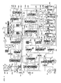
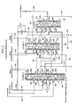
- Un dispositif de commande hydraulique appliqué à une transmission de vitesses automatique d'un véhicule, tel qu'un véhicule automobile, présentant un mécanisme de changement de rapport de transmission comprenant des premier et deuxième embrayages d'entrée (C1, C2) actionnés hydrauliquement, disposés parallèlement, susceptibles d'être embrayés sélectivement, de telle manière que ledit premier embrayage d'entrée (C1) seulement soit embrayé, tandis que ledit deuxième embrayage d'entrée (C2) et un autre embrayage d'entrée, si il y en a un, soient désembrayés, de façon à assurer une première gamme de rapports de transmission marche avant (premier rapport de transmission), et ledit premier embrayage d'entrée (C1) est débrayé tandis que ledit deuxième embrayage (C2) est embrayé, de façon à assurer une deuxième gamme de rapports de transmission (quatrième gamme de rapports de transmission), comprenant :
une première valve de commutation de pression hydraulique (270), ayant un orifice d'entrée (274) destiné à recevoir une pression hydraulique d'entrée, un orifice de sortie (282) relié audit premier embrayage d'entrée (C1) et un orifice de purge (280), et susceptible d'être commutée entre une première position de commutation (haute), servant à connecter son dit orifice de sortie à son dit orifice d'entrée, tout en isolant son dit orifice de sortie par rapport à son dit orifice de purge, et une deuxième position de commutation (basse), servant à connecter son dit orifice de sortie à son dit orifice de purge, tout en isolant son dit orifice de sortie par rapport à son dit orifice d'entrée; et
une deuxième valve de commutation de pression hydraulique (240), ayant un orifice d'entrée (246) destiné à recevoir une pression hydraulique d'entrée, un orifice de sortie (254) connecté audit deuxième embrayage d'entrée (C1) et un orifice de purge (252), et susceptible d'être commutée entre une première position de commutation (haute), servant a connecter son dit orifice de sortie à son dit orifice d'entrée, tout en isolant son dit orifice de sortie par rapport à son dit orifice de purge, et une deuxième position de commutation basse (20), servant à connecter son dit orifice de sortie à son dit orifice de purge, tout en isolant son dit orifice de sortie par rapport à son dit orifice d'entrée;
caractérisé en ce que
ladite deuxième valve de commutation de pression hydraulique (240) comprend en outre un orifice de sécurité intrinsèque (260) susceptible d'être connecté à un orifice de purge (253), lors d'une commutation vers ladite première position de commutation (haute) et d'être connecté à son dit orifice d'entrée (246), lors d'une commutation vers ladite deuxième position de commutation (basse), et
des moyens de passage (268, 269, 280 sur les figures 4 à 7; 268, 296, 298 sur les figures 8 et 10), servant à transmettre la pression hydraulique appliquée audit orifices de sécurité intrinsèque (260), de ladite deuxième valve de commutation de pression hydraulique (240), audit premier embrayage (C1), lorsque ladite première valve de commutation de pression hydraulique est dans ladite deuxième position de commutation (basse). - Un dispositif de commande hydraulique selon la revendication 1, dans laquelle lesdits moyens de passage comprennent un moyen de passage (268) servant à connecter ledit orifice de sécurité intrinsèque (260) de ladite deuxième valve de commutation de pression hydraulique (240) audit orifice de purge (280) de ladite première valve de commutation de pression hydraulique (270).
- Un dispositif de commande hydraulique selon la revendication 1, dans lequel lesdits moyens de passage comprennent une unidirectionnelle ou double valve d'arrêt de commutation (298) ayant un premier et un deuxième orifices d'entrée, un orifice de sortie et un élément de prévu entre ces dits premier et deuxième orifices d'entrée, de manière à permettre seulement à l'un parmi ces dits premier et deuxième orifices d'entrée d'être connecté à un moment donné à son orifice de sortie, un moyen de passage (290) servant à connecter ledit orifice de sortie (282) de ladite première valve de commutation de pression hydraulique (270) audit premier orifice d'entrée de ladite première valve de commutation unidirectionnelle (298), des moyens de passage (268, 296) servant à connecter ledit orifice de sécurité intrinsèque (260) de ladite deuxième valve de commutation de pression hydraulique (240) audit deuxième orifice d'entrée de ladite première valve de commutation unidirectionnelle (298), et un moyen de passage (294) servant à connecter ledit orifice de sortie de ladite première valve de commutation unidirectionnelle (298) audit premier embrayage d'entrée (C1).
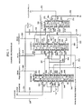
- Un dispositif de commande hydraulique selon la revendication 1, 2 ou 3, dans lequel ledit mécanisme de changement de gamme de rapports de transmission comprend en outre un troisième embrayage d'entrée (C4) actionné hydrauliquement, destiné a étre embrayé de façon a assurer ladite deuxième gamme de rapports de transmission (4e gamme de rapports), comprenant en outre une troisième valve de commutation de pression hydraulique (210) ayant un orifice d'entrée (214) destiné à recevoir une pression hydraulique d'entrée, un orifice de sortie (224) connecté audit troisième embrayage d'entrée (C4) et un orifice de purge/sécurité intrinsèque (222) et susceptible d'être commutée entre une première position de commutation (haute), servant à connecter son orifice de sortie à son orifice d'entrée, tout en isolant son orifice de sortie par rapport à son orifice de purge/sécurité intrinsèque, et une deuxième position de commutation (basse), servant à connecter son orifice de sortie à son orifice de purge/sécurité intrinsèque, tout en isolant son orifice de sortie par rapport à son orifice d'entrée, et un moyen de passage (265) servant à connecter ledit orifice de purge/sécurité intrinsèque (222) de ladite troisième valve de commutation de pression hydraulique (210) audit orifice de sortie (254) de ladite deuxième valve de commutation de pression hydraulique (240).
- Un dispositif de commande hydraulique selon la revendication 1, 2 ou 3, dans lequel ledit mécanisme de changement de gamme de rapport comprend en outre un troisième embrayage d'entrée (C4) actionné hydrauliquement, destiné à être embrayé de façon a assurer ladite deuxième gamme de rapports de transmission (4e étage de rapport de transmission), comprenant en outre une troisième valve de commutation de pression hydraulique (210) ayant un orifice d'entrée (214) destiné à recevoir une pression hydraulique d'entrée, un orifice de sortie (224) connecté audit troisième embrayage d'entrée (C4), et un orifice de purge (222), et susceptible d'être commutée entre une première position de commutation (haute), servant à connecter son orifice de sortie à son orifice d'entrée, tout en isolant son orifice de sortie par rapport à son orifice de purge, et une deuxième position de commutation (basse), servant à connecter son orifice de sortie à son orifice de purge, tout en isolant son orifice de sortie par rapport à son orifice d'entrée, et un moyen de passage présentant une valve de commutation unidirectionnelle (299) ayant un premier et un deuxième orifices d'entrée, un orifice de sortie et un élément de valve prévu entre ces premier et deuxième orifices d'entrée, de manière à permettre à l'un seulement parmi ces premier et deuxième orifices d'entrée d'être connecté à un moment donné à son orifice de sortie, un moyen de passage (263, 295) servant à connecter ledit orifice de sortie (254) de ladite deuxième valve de commutation de pression hydraulique (240) audit premier orifice d'entrée de ladite valve de commutation unidirectionnelle (299) mentionnée en dernier, un moyen de passage (225) servant à connecter ledit orifice de sortie (224) de ladite troisième valve de commutation de pression hydraulique (210) audit deuxième orifice d'entrée de ladite valve de commutation unidirectionnelle (299) mentionnée en dernier.
Applications Claiming Priority (4)
| Application Number | Priority Date | Filing Date | Title |
|---|---|---|---|
| JP192965/88 | 1988-08-02 | ||
| JP192966/88 | 1988-08-02 | ||
| JP63192966A JP2658228B2 (ja) | 1988-08-02 | 1988-08-02 | 車輌用自動変速機の油圧制御装置 |
| JP63192965A JP2829976B2 (ja) | 1988-08-02 | 1988-08-02 | 車輌用自動変速機の油圧制御装置 |
Publications (3)
| Publication Number | Publication Date |
|---|---|
| EP0354006A2 EP0354006A2 (fr) | 1990-02-07 |
| EP0354006A3 EP0354006A3 (fr) | 1992-03-04 |
| EP0354006B1 true EP0354006B1 (fr) | 1995-01-25 |
Family
ID=26507619
Family Applications (1)
| Application Number | Title | Priority Date | Filing Date |
|---|---|---|---|
| EP89307830A Expired - Lifetime EP0354006B1 (fr) | 1988-08-02 | 1989-08-01 | Commande hydraulique pour transmissions automatiques de véhicule ayant deux accouplements d'entrée parallèles |
Country Status (3)
| Country | Link |
|---|---|
| US (1) | US5014577A (fr) |
| EP (1) | EP0354006B1 (fr) |
| DE (1) | DE68920792T2 (fr) |
Families Citing this family (12)
| Publication number | Priority date | Publication date | Assignee | Title |
|---|---|---|---|---|
| EP0398344B1 (fr) * | 1989-05-18 | 1996-01-17 | Nissan Motor Co., Ltd. | Dispositif de sécurité pour le changement des vitesses de la transmission auxiliaire d'une boîte automatique |
| JP2701098B2 (ja) * | 1991-07-31 | 1998-01-21 | 本田技研工業株式会社 | 車両用自動変速機の油圧制御装置 |
| US5409434A (en) * | 1992-01-30 | 1995-04-25 | Toyota Jidosha Kabushiki Kaisha | Control system with failsafe for shift-by-wire automatic transmission |
| JPH06341536A (ja) * | 1993-06-03 | 1994-12-13 | Aisin Aw Co Ltd | 自動変速機の油圧制御装置 |
| JPH07332482A (ja) * | 1994-05-31 | 1995-12-22 | Nippon Soken Inc | 車両用自動変速装置 |
| DE4431073A1 (de) * | 1994-09-01 | 1996-03-07 | Zahnradfabrik Friedrichshafen | Automatgetriebe mit Notlauf |
| KR100220059B1 (ko) * | 1994-12-28 | 1999-09-01 | 정몽규 | 자동차용 4속 자동 변속기의 유압제어 시스템 |
| US5738602A (en) * | 1995-10-24 | 1998-04-14 | Honda Giken Kogyo Kabushiki Kaisha | Oil pressure control system for automatic vehicle transmission |
| JP4269399B2 (ja) * | 1999-03-23 | 2009-05-27 | アイシン・エィ・ダブリュ株式会社 | 自動変速機の油圧制御装置 |
| JP4490172B2 (ja) * | 2004-05-31 | 2010-06-23 | トヨタ自動車株式会社 | 車両用自動変速機の油圧制御装置 |
| DE102006054253A1 (de) * | 2006-11-17 | 2008-05-21 | Zf Friedrichshafen Ag | Verfahren zur Notbetätigung eines automatisierten Fahrzeug-Doppelkupplungsgetriebes |
| CN103542088A (zh) * | 2013-09-30 | 2014-01-29 | 哈尔滨东安汽车发动机制造有限公司 | 失效保护阀 |
Citations (1)
| Publication number | Priority date | Publication date | Assignee | Title |
|---|---|---|---|---|
| EP0302723A2 (fr) * | 1987-08-05 | 1989-02-08 | Toyota Jidosha Kabushiki Kaisha | Dispositif de changement de vitesses du type engrenage planétaire ayant un embrayage unidirectionnel opérationnel en deux fonctions |
Family Cites Families (13)
| Publication number | Priority date | Publication date | Assignee | Title |
|---|---|---|---|---|
| JPS4932047A (fr) * | 1972-07-28 | 1974-03-23 | ||
| DE2352939C2 (de) * | 1973-10-23 | 1984-07-05 | Robert Bosch Gmbh, 7000 Stuttgart | Hydraulische Steuervorrichtung, insbesondere für eine Gangwechseleinrichtung in automatischen Kraftfahrzeuggetrieben |
| US4082009A (en) * | 1976-12-13 | 1978-04-04 | General Motors Corporation | Range shift control by input governor |
| JPS5825179B2 (ja) * | 1978-02-17 | 1983-05-26 | トヨタ自動車株式会社 | 絞り制御弁 |
| JPS5540323A (en) * | 1978-09-14 | 1980-03-21 | Honda Motor Co Ltd | Control device for oil hydraulic operation type transmission for vehicle |
| US4346626A (en) * | 1978-12-27 | 1982-08-31 | Aisin-Warner K.K. | Control device for automatic transmission |
| JPS57167529A (en) * | 1981-04-08 | 1982-10-15 | Aisin Seiki Co Ltd | Control system for torque convertor equipped with direct connection clutch |
| JPS6071751U (ja) * | 1983-10-22 | 1985-05-21 | 本田技研工業株式会社 | 自動変速機の変速制御装置 |
| US4660442A (en) * | 1984-05-14 | 1987-04-28 | Honda Giken Kogyo K.K. | Creep-inhibiting device for an automotive vehicle equipped with an automatic transmission |
| JPS6182055A (ja) * | 1984-09-13 | 1986-04-25 | Honda Motor Co Ltd | 自動変速機の制御装置 |
| FR2570458B1 (fr) * | 1984-09-18 | 1990-03-02 | Renault | Dispositif et procedes de commande d'une transmission automatique a quatre rapports |
| JPS61248960A (ja) * | 1985-04-26 | 1986-11-06 | Mazda Motor Corp | 自動変速機の変速制御装置 |
| JPH0794865B2 (ja) * | 1987-04-09 | 1995-10-11 | アイシン・エィ・ダブリュ株式会社 | 自動変速機における油圧制御装置 |
-
1989
- 1989-08-01 DE DE68920792T patent/DE68920792T2/de not_active Expired - Fee Related
- 1989-08-01 EP EP89307830A patent/EP0354006B1/fr not_active Expired - Lifetime
- 1989-08-02 US US07/388,485 patent/US5014577A/en not_active Expired - Lifetime
Patent Citations (1)
| Publication number | Priority date | Publication date | Assignee | Title |
|---|---|---|---|---|
| EP0302723A2 (fr) * | 1987-08-05 | 1989-02-08 | Toyota Jidosha Kabushiki Kaisha | Dispositif de changement de vitesses du type engrenage planétaire ayant un embrayage unidirectionnel opérationnel en deux fonctions |
Also Published As
| Publication number | Publication date |
|---|---|
| EP0354006A3 (fr) | 1992-03-04 |
| DE68920792D1 (de) | 1995-03-09 |
| US5014577A (en) | 1991-05-14 |
| EP0354006A2 (fr) | 1990-02-07 |
| DE68920792T2 (de) | 1995-06-01 |
Similar Documents
| Publication | Publication Date | Title |
|---|---|---|
| EP0354006B1 (fr) | Commande hydraulique pour transmissions automatiques de véhicule ayant deux accouplements d'entrée parallèles | |
| US5115696A (en) | Hydraulic pressure control device with parallel pressure supply passages for certain one friction engaging means | |
| US5010787A (en) | Hydraulic control device for automatic transmission for vehicle adapted to engage clutch at different speed according to engine output power | |
| EP0354007B1 (fr) | Dispositif de commande hydraulique pour transmission automatique de véhicule comprenant des éléments d'engagement à friction activés pendant des rapports non séquentiels | |
| US5029493A (en) | Hydraulic control device in automatic transmission in vehicle equipped with electronic throttle opening control device | |
| US4984486A (en) | Hydraulic pressure control device for automatic transmission for vehicle including reverse stage prevention system | |
| US5033331A (en) | Hydraulic control device for automatic transmission for vehicle having clutch operable in two speed stages and two parallel hydraulic pressure supply passages therefor | |
| US4987798A (en) | Hydraulic control device for automatic transmission for vehicle with high accuracy reverse inhibition system | |
| US5012700A (en) | Hydraulic control device for automatic transmission for vehicle having clutch disengage control means independent of clutch engage control means | |
| US4920829A (en) | Hydraulic pressure control device for automatic transmission for vehicle including reverse stage and lock-up clutch control systems | |
| EP0330322B1 (fr) | Dispositif de commande hydraulique sous pression pour transmission automatique de véhicule comprenant un système de prévention de la marche arrière | |
| US5984818A (en) | Hydraulic control system for automatic transmissions | |
| US5176046A (en) | Control system for an automatic transmission | |
| US4779492A (en) | Twin type hydraulic pressure control device with individual line pressure regulation valves for two stage automatic transmission | |
| JP2658228B2 (ja) | 車輌用自動変速機の油圧制御装置 | |
| JP3057680B2 (ja) | 車輌用自動変速機の油圧制御装置のシフト弁 | |
| JP3342168B2 (ja) | 自動変速機の油圧制御装置 | |
| JP2926714B2 (ja) | 車輌用自動変速機の油圧制御装置 | |
| JP2913649B2 (ja) | 車輌用自動変速機の油圧制御装置 | |
| JPH02134459A (ja) | 車輌用自動変速機のロックアップクラッチ制御用油圧制御装置 | |
| JP2829976B2 (ja) | 車輌用自動変速機の油圧制御装置 | |
| JPH05149427A (ja) | 車両用自動変速機の油圧制御装置 | |
| JPH03134362A (ja) | 車輌用自動変速機の油圧制御装置 | |
| JPH0560210A (ja) | 自動変速機の油圧制御装置 | |
| JPH02125166A (ja) | 車輌用自動変速機の油圧制御装置 |
Legal Events
| Date | Code | Title | Description |
|---|---|---|---|
| PUAI | Public reference made under article 153(3) epc to a published international application that has entered the european phase |
Free format text: ORIGINAL CODE: 0009012 |
|
| AK | Designated contracting states |
Kind code of ref document: A2 Designated state(s): DE FR GB |
|
| PUAL | Search report despatched |
Free format text: ORIGINAL CODE: 0009013 |
|
| AK | Designated contracting states |
Kind code of ref document: A3 Designated state(s): DE FR GB |
|
| 17P | Request for examination filed |
Effective date: 19920221 |
|
| 17Q | First examination report despatched |
Effective date: 19930803 |
|
| GRAA | (expected) grant |
Free format text: ORIGINAL CODE: 0009210 |
|
| AK | Designated contracting states |
Kind code of ref document: B1 Designated state(s): DE FR GB |
|
| ET | Fr: translation filed | ||
| REF | Corresponds to: |
Ref document number: 68920792 Country of ref document: DE Date of ref document: 19950309 |
|
| PLBE | No opposition filed within time limit |
Free format text: ORIGINAL CODE: 0009261 |
|
| STAA | Information on the status of an ep patent application or granted ep patent |
Free format text: STATUS: NO OPPOSITION FILED WITHIN TIME LIMIT |
|
| 26N | No opposition filed | ||
| REG | Reference to a national code |
Ref country code: GB Ref legal event code: 746 Effective date: 19980106 |
|
| REG | Reference to a national code |
Ref country code: FR Ref legal event code: D6 |
|
| REG | Reference to a national code |
Ref country code: GB Ref legal event code: IF02 |
|
| PGFP | Annual fee paid to national office [announced via postgrant information from national office to epo] |
Ref country code: DE Payment date: 20070726 Year of fee payment: 19 |
|
| PGFP | Annual fee paid to national office [announced via postgrant information from national office to epo] |
Ref country code: GB Payment date: 20070801 Year of fee payment: 19 |
|
| PGFP | Annual fee paid to national office [announced via postgrant information from national office to epo] |
Ref country code: FR Payment date: 20070808 Year of fee payment: 19 |
|
| GBPC | Gb: european patent ceased through non-payment of renewal fee |
Effective date: 20080801 |
|
| REG | Reference to a national code |
Ref country code: FR Ref legal event code: ST Effective date: 20090430 |
|
| PG25 | Lapsed in a contracting state [announced via postgrant information from national office to epo] |
Ref country code: FR Free format text: LAPSE BECAUSE OF NON-PAYMENT OF DUE FEES Effective date: 20080901 Ref country code: DE Free format text: LAPSE BECAUSE OF NON-PAYMENT OF DUE FEES Effective date: 20090303 |
|
| PG25 | Lapsed in a contracting state [announced via postgrant information from national office to epo] |
Ref country code: GB Free format text: LAPSE BECAUSE OF NON-PAYMENT OF DUE FEES Effective date: 20080801 |