EP0353771A2 - Dispositif pour commander des changements de rapports dans des transmissions automatiques - Google Patents
Dispositif pour commander des changements de rapports dans des transmissions automatiques Download PDFInfo
- Publication number
- EP0353771A2 EP0353771A2 EP89114456A EP89114456A EP0353771A2 EP 0353771 A2 EP0353771 A2 EP 0353771A2 EP 89114456 A EP89114456 A EP 89114456A EP 89114456 A EP89114456 A EP 89114456A EP 0353771 A2 EP0353771 A2 EP 0353771A2
- Authority
- EP
- European Patent Office
- Prior art keywords
- gearshift
- clutch
- gear
- time
- torque
- Prior art date
- Legal status (The legal status is an assumption and is not a legal conclusion. Google has not performed a legal analysis and makes no representation as to the accuracy of the status listed.)
- Granted
Links
Images


Classifications
-
- F—MECHANICAL ENGINEERING; LIGHTING; HEATING; WEAPONS; BLASTING
- F16—ENGINEERING ELEMENTS AND UNITS; GENERAL MEASURES FOR PRODUCING AND MAINTAINING EFFECTIVE FUNCTIONING OF MACHINES OR INSTALLATIONS; THERMAL INSULATION IN GENERAL
- F16H—GEARING
- F16H61/00—Control functions within control units of change-speed- or reversing-gearings for conveying rotary motion ; Control of exclusively fluid gearing, friction gearing, gearings with endless flexible members or other particular types of gearing
- F16H61/04—Smoothing ratio shift
- F16H61/06—Smoothing ratio shift by controlling rate of change of fluid pressure
- F16H61/061—Smoothing ratio shift by controlling rate of change of fluid pressure using electric control means
-
- F—MECHANICAL ENGINEERING; LIGHTING; HEATING; WEAPONS; BLASTING
- F16—ENGINEERING ELEMENTS AND UNITS; GENERAL MEASURES FOR PRODUCING AND MAINTAINING EFFECTIVE FUNCTIONING OF MACHINES OR INSTALLATIONS; THERMAL INSULATION IN GENERAL
- F16H—GEARING
- F16H59/00—Control inputs to control units of change-speed-, or reversing-gearings for conveying rotary motion
- F16H59/68—Inputs being a function of gearing status
- F16H2059/6807—Status of gear-change operation, e.g. clutch fully engaged
-
- F—MECHANICAL ENGINEERING; LIGHTING; HEATING; WEAPONS; BLASTING
- F16—ENGINEERING ELEMENTS AND UNITS; GENERAL MEASURES FOR PRODUCING AND MAINTAINING EFFECTIVE FUNCTIONING OF MACHINES OR INSTALLATIONS; THERMAL INSULATION IN GENERAL
- F16H—GEARING
- F16H61/00—Control functions within control units of change-speed- or reversing-gearings for conveying rotary motion ; Control of exclusively fluid gearing, friction gearing, gearings with endless flexible members or other particular types of gearing
- F16H2061/0075—Control functions within control units of change-speed- or reversing-gearings for conveying rotary motion ; Control of exclusively fluid gearing, friction gearing, gearings with endless flexible members or other particular types of gearing characterised by a particular control method
- F16H2061/0078—Linear control, e.g. PID, state feedback or Kalman
-
- F—MECHANICAL ENGINEERING; LIGHTING; HEATING; WEAPONS; BLASTING
- F16—ENGINEERING ELEMENTS AND UNITS; GENERAL MEASURES FOR PRODUCING AND MAINTAINING EFFECTIVE FUNCTIONING OF MACHINES OR INSTALLATIONS; THERMAL INSULATION IN GENERAL
- F16H—GEARING
- F16H61/00—Control functions within control units of change-speed- or reversing-gearings for conveying rotary motion ; Control of exclusively fluid gearing, friction gearing, gearings with endless flexible members or other particular types of gearing
- F16H2061/0075—Control functions within control units of change-speed- or reversing-gearings for conveying rotary motion ; Control of exclusively fluid gearing, friction gearing, gearings with endless flexible members or other particular types of gearing characterised by a particular control method
- F16H2061/0087—Adaptive control, e.g. the control parameters adapted by learning
-
- F—MECHANICAL ENGINEERING; LIGHTING; HEATING; WEAPONS; BLASTING
- F16—ENGINEERING ELEMENTS AND UNITS; GENERAL MEASURES FOR PRODUCING AND MAINTAINING EFFECTIVE FUNCTIONING OF MACHINES OR INSTALLATIONS; THERMAL INSULATION IN GENERAL
- F16H—GEARING
- F16H61/00—Control functions within control units of change-speed- or reversing-gearings for conveying rotary motion ; Control of exclusively fluid gearing, friction gearing, gearings with endless flexible members or other particular types of gearing
- F16H61/02—Control functions within control units of change-speed- or reversing-gearings for conveying rotary motion ; Control of exclusively fluid gearing, friction gearing, gearings with endless flexible members or other particular types of gearing characterised by the signals used
- F16H61/0202—Control functions within control units of change-speed- or reversing-gearings for conveying rotary motion ; Control of exclusively fluid gearing, friction gearing, gearings with endless flexible members or other particular types of gearing characterised by the signals used the signals being electric
- F16H61/0251—Elements specially adapted for electric control units, e.g. valves for converting electrical signals to fluid signals
- F16H2061/0258—Proportional solenoid valve
-
- F—MECHANICAL ENGINEERING; LIGHTING; HEATING; WEAPONS; BLASTING
- F16—ENGINEERING ELEMENTS AND UNITS; GENERAL MEASURES FOR PRODUCING AND MAINTAINING EFFECTIVE FUNCTIONING OF MACHINES OR INSTALLATIONS; THERMAL INSULATION IN GENERAL
- F16H—GEARING
- F16H61/00—Control functions within control units of change-speed- or reversing-gearings for conveying rotary motion ; Control of exclusively fluid gearing, friction gearing, gearings with endless flexible members or other particular types of gearing
- F16H61/04—Smoothing ratio shift
- F16H2061/0477—Smoothing ratio shift by suppression of excessive engine flare or turbine racing during shift transition
-
- F—MECHANICAL ENGINEERING; LIGHTING; HEATING; WEAPONS; BLASTING
- F16—ENGINEERING ELEMENTS AND UNITS; GENERAL MEASURES FOR PRODUCING AND MAINTAINING EFFECTIVE FUNCTIONING OF MACHINES OR INSTALLATIONS; THERMAL INSULATION IN GENERAL
- F16H—GEARING
- F16H59/00—Control inputs to control units of change-speed-, or reversing-gearings for conveying rotary motion
- F16H59/74—Inputs being a function of engine parameters
-
- F—MECHANICAL ENGINEERING; LIGHTING; HEATING; WEAPONS; BLASTING
- F16—ENGINEERING ELEMENTS AND UNITS; GENERAL MEASURES FOR PRODUCING AND MAINTAINING EFFECTIVE FUNCTIONING OF MACHINES OR INSTALLATIONS; THERMAL INSULATION IN GENERAL
- F16H—GEARING
- F16H61/00—Control functions within control units of change-speed- or reversing-gearings for conveying rotary motion ; Control of exclusively fluid gearing, friction gearing, gearings with endless flexible members or other particular types of gearing
- F16H61/04—Smoothing ratio shift
- F16H61/08—Timing control
-
- F—MECHANICAL ENGINEERING; LIGHTING; HEATING; WEAPONS; BLASTING
- F16—ENGINEERING ELEMENTS AND UNITS; GENERAL MEASURES FOR PRODUCING AND MAINTAINING EFFECTIVE FUNCTIONING OF MACHINES OR INSTALLATIONS; THERMAL INSULATION IN GENERAL
- F16H—GEARING
- F16H61/00—Control functions within control units of change-speed- or reversing-gearings for conveying rotary motion ; Control of exclusively fluid gearing, friction gearing, gearings with endless flexible members or other particular types of gearing
- F16H61/68—Control functions within control units of change-speed- or reversing-gearings for conveying rotary motion ; Control of exclusively fluid gearing, friction gearing, gearings with endless flexible members or other particular types of gearing specially adapted for stepped gearings
- F16H61/684—Control functions within control units of change-speed- or reversing-gearings for conveying rotary motion ; Control of exclusively fluid gearing, friction gearing, gearings with endless flexible members or other particular types of gearing specially adapted for stepped gearings without interruption of drive
Definitions
- the present invention relates to a vehicular automatic transmission for automatically shifting gears by changing power transmission paths through engagement and disengagement of gear shift means (e.g., hydraulically operated clutches).
- gear shift means e.g., hydraulically operated clutches
- Automatic transmissions are arranged to shift gears automatically depending on running conditions of a motor vehicle to achieve desired vehicle running characteristics. It is customary to provide a gearshift map composed of upshifting and downshifting curves for each gear position, the curves being established in relation to the vehicle speed and the engine power output, and to control the automatic transmission to shift the gears according to the gearshift map dependent on the running conditions as indicated on the gearshift map.
- gear shifting control is disclosed in Japanese Laid-Open Patent Publication No. 61-189354, for example.
- One type of automatic transmission includes a power transmission means comprising a plurality of power transmission paths (e.g., a plurality of gear trains), a plurality of gearshift means (e.g., a plurality of hydraulically operated clutches) for selecting the power transmission paths, and a control means (e.g., a hydraulic pressure control valve) for controlling operation of the gearshift means.
- a power transmission means comprising a plurality of power transmission paths (e.g., a plurality of gear trains), a plurality of gearshift means (e.g., a plurality of hydraulically operated clutches) for selecting the power transmission paths, and a control means (e.g., a hydraulic pressure control valve) for controlling operation of the gearshift means.
- the speed reduction ratio (gear ratio) of a previous gear position i.e., a gear position provided by the power transmission path (gear train) selected until a gearshift command is issued
- a gear position provided by the power transmission path selected by the gearshift command is different from the speed reduction ratio of a next gear position (i.e., a gear position provided by the power transmission path selected by the gearshift command). Therefore, when such a gearshift is effected, it is necessary that the automatic transmission be controlled so as not to produce a gearshift shock and a gearshift delay.
- a clutch engaging torque which will provide desired gearshift characteristics free of gearshift shocks and delays is calculated based on an engine torque to be transmitted from the engine to the hydraulically operated clutch for the next gear position, and the hydraulic pressure to be supplied to the clutch is controlled in order to produce the calculated clutch engaging torque.
- the hydraulic pressure which produces the calculated clutch engaging torque required for a gearshift has been calculated from the pushing force of the piston of the hydraulically operated clutch which will be developed by the hydraulic pressure, and the coefficient of friction of the friction plates of the hydraulically operated clutch.
- the hydraulically operated clutch is often mounted on the rotatable shaft of the automatic transmission. Since the hydraulically operated clutch mounted on the transmission shaft is rotated itself, it develops centrifugal forces in the oil in the hydraulic pressure chamber of the clutch because of the centrifugal forces to which the clutch is subjected.
- the rate of change of the engine rotational speed in a gearshift is compared with a target rate of change, and the hydraulic pressure to be supplied to the hydraulically operated clutch is controlled by a feedback control loop so that the actual rate of change in the engine rotational speed will reach the target rate of change.
- a feedback control loop so that the actual rate of change in the engine rotational speed will reach the target rate of change.
- Each of the gearshift means is often in the form of a friction clutch.
- the coefficient of friction of a friction clutch varies depending on the slip rate between the friction surfaces thereof (i.e., the relative speed between the input and output members of the clutches. Accordingly, even if the hydraulic pressure supplied to the hydraulically operated friction clutch is accurately controlled, since the coefficient of friction of the friction clutch varies, the clutch engaging forces vary, making it difficult to provide desired clutch engaging characteristics.
- the friction characteristics of the clutch differ depending on the material of the friction surfaces and the lubricating oil of the clutch.
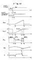
- FIG. 13 of the accompanying drawings illustrates one characteristic curve of the coefficient of friction by way of example.
- the graph of FIG. 13 shows the results of a test which was conducted using the SAE No. 2 friction testing machine.
- the dynamic coefficient ⁇ k of friction does not vary largely as long as the slip rate is large, but has a large value immediately before the clutch is directly engaged (i.e,. in the vicinity of a time t2). Therefore, as indicated by the solid-line curve, the value of torque T for frictionally engaging the clutch becomes a sharply increasing value immediately before the time t2.
- the coefficient of friction immediately before the clutch is directly engaged is called a final dynamic coefficient ⁇ 0 of friction.
- Gearshift shocks are made smaller as the time required to effect gearshifts is longer.
- the gearshift time should however be selected to of an appropriate value because if the gearshift time were too long, the durability of frictional elements of the gearshift means would be adversely affected, and the driver of the vehicle would feel uneasy about the operation of the transmission.
- the gear-shift time is equal to the time in which the input and output members of the gearshift means slip with respect to each other.
- the gearshift time can be of a suitable value by setting the rate of change of the ratio of the rotational speed of the input member to the rotational speed of the output member to an appropriate value.
- a torque converter is disposed between the engine and the automatic transmission.
- the transmission cannot suitably be controlled because of the slippage of the torque converter.
- the slippage of the torque converter varies greatly, and appropriate transmission control cannot be achieved based on the engine rotational speed.
- control modes for automatic transmissions including a power-on/upshift mode in which the accelerator pedal is depressed and the transmission is shifted up, and a power-off/downshift mode in which the accelerator pedal is released during running of the vehicle and the transmission is shifted down as the vehicle speed is lowered.
- a power-on/upshift mode in which the accelerator pedal is depressed and the transmission is shifted up
- a power-off/downshift mode in which the accelerator pedal is released during running of the vehicle and the transmission is shifted down as the vehicle speed is lowered.
- the difference between the rotational speeds of the input and output members of the next-gear-position gearshift means would be increased (i.e., the rotational speeds of the input and output members vary away from a synchronized speed) if the next-gear-position gearshift means remained disengaged. It is therefore necessary that the next-gear-position gearshift means start to be engaged at a proper timing.
- the time lag can be shortened by increasing the hydraulic pressure to be supplied to the next-gear-position gearshift means when a gearshift command is issued. If the hydraulic pressure were too high, the next-gear-position gearshift means would be engaged too abruptly, producing a gearshift shock.
- Another object of the present invention is to provide a transmission gearshift control apparatus for setting hydraulic pressures for hydraulically operated clutches serving as gearshift means so that an automatic transmission can be controlled constantly irrespective of different rotational speeds of the hydraulically operated clutches, i.e., different vehicle speeds and engine speeds.
- Still another object of the present invention is to provide a transmission gearshift control apparatus for controlling an automatic transmission to reduce variations in the torque applied to engage friction clutches serving as gearshift means when gearshifts are effected, particularly immediately before the clutches are engaged.
- Yet another object of the present invention is to provide a transmission gearshift control apparatus for controlling an automatic transmission without being affected by the slippage of a torque converter and hence gearshift shocks.
- a further object of the present invention is to provide a transmission gearshift control apparatus which sets a time lag before a gearshift means starts operating in a power-on/upshift mode and a power-off/downshift mode to an appropriate value for effecting good transmission control.
- a clutch engaging torque which will be required by a hydraulically operated clutch to be engaged for a gearshift is preset, a hydraulic pressure required to obtain the clutch engaging torque while the hydraulically operated clutch is at rest is calculated, and a corrective action is effected by, for example, subtracting from the hydraulic pressure a centrifugal hydraulic pressure which will be developed in the hydraulically operated clutch by the rotation thereof in the gearshift, thus determining a hydraulic pressure to operate the hydraulically operated clutch.
- FIG. 1 schematically shows an automatic transmission which is mounted on a motor vehicle and controlled by a transmission gearshift control apparatus, the automatic transmission having hydraulically operated clutches operable by hydraulic pressures determined by the transmission gearshift control apparatus.
- the automatic transmission generally denoted at AT, has a transmission mechanism 10 comprising a plurality of gear trains for changing the speed of rotation of the engine power output transmitted from a torque converter 2 and for applying the engine power output to an output shaft 6. More specifically, the engine power output from the torque converter 2 is applied to an input shaft 3, and then transmitted, while its rotational speed is being changed, to a countershaft 4 extending parallel to the input shaft 3 through a selected one of five gear trains disposed parallel between the input shaft 3 and the counter-shaft 4. The engine power output is then applied from the countershaft 4 to the output shaft 6 through output gears 5a, 5b disposed between the countershaft 4 and the output shaft 6.
- the five gear trains between the input shaft and the countershaft 4 include a gear train composed of gears 11a, 11b for a first gear position, a gear train composed of gears 12a, 12b for a second gear position, a gear train composed of gears 13a, 13b for a third gear position, a gear train composed of gears 14a, 14b for a fourth gear position, and a gear train composed of gears 15a, 15b, 15c for a reverse gear position.
- These gear trains are associated respectively with hydraulically operated clutches 11c, 12c, 13c, 14c, 15d for enabling the gear trains to transmit the engine power output from the input shaft 3 to the counter-shaft 4.
- a one-way clutch 11d is disposed in the gear 11b.
- the five hydraulically operated clutches 11c through 15d are controlled in operation by a hydraulic pressure supplied and discharged through hydraulic pressure lines 21a through 21e from and to a hydraulic pressure control valve assembly 20.
- the hydraulic pressure control valve assembly 20 is operated by a manual spool valve 25 coupled by a wire 45a to a shift lever 45 movable by the driver, two solenoid valves 22, 23, and a linear solenoid valve 56.
- the solenoid valves 22, 23 are selectively actuated and inactivated by operating signals supplied from a controller 30 through signal lines 31a, 31b.
- the linear solenoid valve 56 is operated by a signal supplied from the controller 30 via a signal line 31c.
- the controller 30 is supplied with a rotational speed signal fed via a signal line 35a from a first rotational speed sensor 35 which detects the rotational speed of an input member of the hydraulically operated clutch 15d based on rotation of the reverse gear 15c, a rotational speed signal fed via a signal line 32a from a second rotational speed sensor 32 which detects the rotational speed of an output member of the hydraulically operated clutch 13c based on rotation of the output gear 5b, and a throttle valve opening signal fed via a signal line 33a from a throttle valve opening sensor 33 which detects the opening of an engine throttle valve 41.
- Gear shifting control is performed dependent on a shift range selected by the manual valve 25 of the hydraulic pressure control valve assembly 20 in response to manual operation of the shift lever 45.
- Available shift ranges include shift ranges or positions P, R, N, D, S, 2, for example.
- P and N all the clutches 11c through 15d are disengaged and the transmission is in a neutral position.
- the reverse-gear-position clutch 15d is engaged to select the reverse gear position.
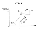
- gear positions are selected based on a gearshift map.
- the gearshift map is composed of an upshifting curve L U and a downshifting curve L D , these curves being plotted in a graph having a vertical axis indicating the throttle valve opening ⁇ TH and a horizontal axis indicating the vehicle speed V.
- the IPD and EPD modes are the same as long as the accelerated condition and the gearshift type are concerned.
- the driver operates the shift lever to effect a downshift in the IPD mode whereas a downshift is automatically effected as the running condition varies in the EPD mode. Therefore, an allowable level of gearshift shock is relatively large in the IPD mode, but is small in the EPD mode.
- Some vehicles have D and S buttons associated with the automatic transmission, the D button being pressed to select slow gearshifts and the S button being pressed to select sporty gearshifts.
- gear shift map of FIG. 2 is shown as having one upshifting curve and one downshifting curve, the gear shift map actually has a plurality of upshifting curves and a plurality of downshifting curves dependent on the number of gear positions available in the transmission.
- the controller 30 applies operating signals over the signal lines 31a, 31b to the solenoid valves 22, 23 to operate the hydraulic pressure control valve assembly 20 to supply hydraulic pressure to and discharge hydraulic pressure from the hydraulically operated clutches 11c through 11d for effecting an upshift or a downshift.
- the hydraulic pressure control valve assembly 20 will be described below with reference to FIG. 3.
- the control valve 20 delivers operating oil supplied from an oil sump 7 by a pump 8 to a regulator valve 50 via a line 101, and the pressure of the delivered operating oil is regulated into a predetermined line pressure by the regulator valve 50.
- the line pressure is applied via a line 110 to the manual spool valve 25 which then selectively supplies the line pressure to the gear position clutches 11c, 12c, 13c, 14c, 15d to control these clutches, dependent on operation of the manual spool valve 25 and various other valves in the control valve assembly 20 according to running conditions of the motor vehicle.
- the various valves in the control valve assembly 20 will be described below.
- the control valve assembly 20 includes a check valve 52 disposed downstream of the regulator valve 50 for preventing the oil of lubricating oil supplied to various parts of the automatic transmission AT via a line 102 from rising beyond a predetermined pressure level.
- a modulator valve 54 reduces the line pressure fed from a line 103 to produce a prescribed modulator pressure.
- the modulator valve 54 then supplies working oil under the modulator pressure via a line 104 to a lockup clutch control circuit (not shown) of the torque converter 2 and also via a line 105 to the first and second solenoid valves 22, 23 for controlling operation of shift valves.
- the manual spool valve 25 is operated in interlinked relation to the shift lever 45 that is manually moved by the driver.
- the manual valve 25 is selectively positioned in any one of six positions P, R, N, D, S, 2 for selectively supplying the line pressure from the line 110 to lines 25a through 25g.
- a 1-2 shift valve 60, a 2-3 shift valve 62, and a 3-4 shift valve 64 are controlled by the modulator pressure supplied via lines 106a through 106f dependent on whether the first and second solenoid valves 22, 23 are turned on or off, for controlling the supply of the line pressure to and the discharge of the line pressure from the clutches 11c, 12c, 13c, 14c for the first through fourth gear positions, respectively.
- the lines 106a, 106b are connected to the first solenoid valve 22 and also to the line 105 through an orifice 22a.
- the solenoid of the first solenoid valve 22 When the solenoid of the first solenoid valve 22 is de-energized, its port leading to a drain is closed, and working oil under the modulator pressure is supplied from the line 105 to the lines 106a, 106b.
- the solenoid of the first solenoid valve 22 When the solenoid of the first solenoid valve 22 is energized, the drain port thereof is opened to reduce the pressure in the lines 106a, 106b substantially to zero.
- the lines 106c through 106f are connected to the second solenoid valve 23 and also to the line 105 via an orifice 23a.
- the drain port thereof is closed to allow the working oil under the modulator pressure to be supplied from the line 105 to the lines 106c through 106f.
- the drain port thereof is opened to reduce the pressure in the lines 106c through 106f substantially to zero.
- the line 106a is connected to the righthand end (as shown) of the 1-2 shift valve 60
- the line 106b is connected to the righthand end of the 2-3 shift valve 62
- the line 106c is connected to the lefthand end of the 1-2 shift valve 60
- the line 106e is connected to the righthand end of the 3-4 shift valve 64
- the line 106f is connected to the lefthand end of the 2-3 shift valve 62.
- the lines 106e, 106f are coupled to the second solenoid valve 23 through the manual valve 25 and the line 106d.
- the operation of the 1-2, 2-3, and 3-4 shift valves 60, 62, 64 can be controlled to selectively supply the line pressure fed from the line 110 via the manual valve 25 to the hydraulically operated clutches 11c, 12c, 13c, 14c for selecting a desired gear position.
- the control valve assembly 20 also has first, second, third, and fourth orifice control valves 70, 72, 74, 76 for releasing hydraulic pressure from the hydraulic pressure chamber in the clutch associated with a previous gear position in timed relation to the development of a pressure buildup in the hydraulic pressure chamber in the clutch associated with a next gear position, when a gear shift is effected. More specifically, the first orifice control valve 70 controls the timing of releasing the hydraulic pressure from the third-gear-position clutch when a downshift is effected from the third gear position to the second gear position.
- the second orifice control valve 72 controls the timing of releasing the hydraulic pressure from the second-gear-position clutch when an upshift is carried out from the second gear position to the third gear position or from the second gear position to the fourth gear position.
- the third orifice control valve 74 controls the timing of releasing the hydraulic pressure from the fourth-gear-position clutch upon a downshift from the fourth gear position to the third gear position or from the fourth gear position to the second gear position.
- the fourth orifice control valve 76 controls the timing of releasing the hydraulic pressure from the third-gear-position clutch at the time of an upshift from the third gear position to the fourth gear position.
- the control valve assembly 20 further includes accumulators 81, 82, 83, 84 having pressure bearing chambers communicating respectively with the hydraulic pressure chambers of the hydraulically operated clutches 11c, 12c, 13c, 14c.
- the accumulators 81, 82, 83, 84 also have back pressure chambers opposite to the respective pressure bearing chambers with pistons 81a, 82a, 83a, 84a therebetween, the back pressure chambers being connected to respective lines 121, 122, 123, 124 which are coupled to the linear solenoid valve 56 via lines 120a, 120a and a line 120.
- the linear solenoid valve 56 has a linear solenoid 56a.
- a current supplied to the linear solenoid 56a is controlled to control the operating force of the linear solenoid valve 56 for controlling the magnitude of a hydraulic pressure (control pressure P TH ) to be supplied to a line 120.
- control pressure P TH control pressure
- a clutch pressure control valve 78 is disposed in a line extending from the manual valve 25 to the 1-2 shift valve 60, and is operated under the control pressure P TH as regulated by the linear solenoid valve 56.
- the line pressure supplied through the shift valves 60, 62, 64 to the hydraulically operated clutches 11c, 12c, 13c, 14c is controlled by the clutch pressure control valve 78 depending on the control pressure P TH .
- the control pressure P TH is controlled so as to correspond to the engine output power, so that the line pressure for operating the clutches may be as low as possible, just enough to produce a necessary torque corresponding to the engine output power.
- the manual valve 25 is operated by the shift lever 45 and the solenoid valves 22, 23 are turned on and off to selectively supply the line pressure to the hydraulically operated clutches 11c, 12c, 13c, 14c for automatically selecting a gear position.
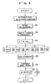
- FIG. 4 shows a main control sequence for determining a clutch engaging torque.
- a step S1 confirms an interrupt process at the time gearshift commands are successivelysively applied in a short period of time, such as for shifting gears from 4th gear position to the third gear position to the second gear position, for example.
- a step S2 determine those of the five shift modes shown in FIG. 2 to which the commanded gearshifts correspond.
- a step S3 determines a timing for controlling the clutch engaging torque, a timing for retarding the engine output power, or the like in each of the shift modes.
- a step S4 calculates the engaging torque CTQ for each of the clutches, and the clutch engaging torques for gearshifts is determined based on the timing determined in the step S3 in the respective shift modes.
- the control pressure P TH is controlled by the linear solenoid valve 56 to control the back pressure of each of the accumulators.
- the back pressure is corrected for the preload produced by a spring acting on the piston in each of the accumulators and also for a centrifugal hydraulic pressure which is developed in the hydraulic pressure chamber of each clutch when the clutch rotates (A OFn correction).
- a necessary current Is to be supplied is sought from a map of linear solenoid currents and control pressures P TH in a step S6, and the current Is is supplied for feedback control in a step S7.
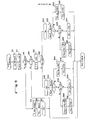
- step S4 of the clutch engaging torque CTQ in the above main control sequence will be described below with reference to the flowchart of FIG. 5.
- an engine output torque ETQ corresponding to the engine rotational speed and the intake vacuum at the time of a gearshift is read from a predetermined engine output map of engine rotational speeds Ne and intake vacuums P B in a step S41. Since the engine output power is retarded in order to effect a smooth gearshift, the engine output power is corrected to such an output retard in a step S42. Since the engine output power is transmitted to the automatic transmission through a torque converter, the engine output power is further corrected for a torque increase caused by the torque converter in a step S43.
- the inertia torque ITQ is a torque required to rotate the inertia of the input member of the clutch which is engaged in the gearshift, depending on the rate of change of the engine rotational speed which is determined from the relationship between a change in the engine rotational speed caused by the gearshift and a desired gearshift time required for the gearshift.
- the inertia torque ITQ is calculated based on the engine rotational speed, the desired gearshift characteristics, and the input member inertia at the time of the gearshift.
- the inertia torque ITQ calculated in the step S45 is added to the engine torque ETQ to determine a torque to be transmitted to the transmission input shaft.
- the torque is corrected for a hydraulic pressure buildup time and an oil temperature in a step S46 (DTQ correction). More specifically, even if the hydraulic pressure is supplied to the clutch at the time of starting to effect a gearshift, there is a time delay before the oil reaches the hydraulic pressure chamber of the clutch and starts to engage the clutch. Therefore, during an initial period of the gearshift, the supplied hydraulic pressure is increased to increase the speed at which the hydraulic pressure is supplied to the clutch thereby shortening the time delay. This correction is effected for a prescribed interval of time after the gearshift is started. The amount of such correction varies with the oil temperature since the time delay differs depending on the viscosity of the oil which depends on the oil temperature.
- the torque thus calculated is the transmission input shaft torque, it is converted into a torque shared by the clutch used for effecting the gearshift in a step S47, and then a force for pressing the clutch piston, which is required to produce the torque share, is calculated from the relationship between the coefficient ⁇ of friction and peripheral speed V of the clutch plates of the clutch in a step S48.
- a hydraulic pressure needed by the clutch can be calculated.
- a control pressure P TH as an accumulator back pressure for developing the hydraulic pressure is then determined.
- the necessary clutch pressure is offset from the control pressure P TH by an amount corresponding to the preload of the spring of the accumulator, and a centrifugal hydraulic pressure is developed in the clutch hydraulic pressure chamber since the clutch is rotating. Therefore, the clutch engaging torque is corrected for the offset and the centrifugal hydraulic pressure in the A OFn correction at the step S5 shown in FIG. 5.
- the corrective amount A OFn is used to correct the torque for the preload of the spring in the accumulator and the centrifugal hydraulic pressure.
- the spring preload can be recognized as being of a constant value depending on each of the accumulators, and the centrifugal hydraulic pressure can be recognized as having a value corresponding to the square of the rotational speed of the hydraulically operated clutch coupled to each accumulator. If the vehicle speed is known, the rotational speed of each of the hydraulically operated clutches can be derived from the vehicle speed since the gear ratio is known. Therefore, as shown in FIG. 6B, there is provided a table having a plurality of vehicle speed ranges and corrective amounts for the hydraulically operated clutches in the respective vehicle speed ranges.
- the corrective amounts in the table are of values corresponding to the sums of the average centrifugal hydraulic pressures in the vehicle speed ranges and the preloads of the springs. If the vehicle speed and the hydraulically operated clutch in operation are known, therefore, a necessary A OFn corrective amount can be read from the table.
- the shift solenoid output is changed to the target gear position Sa at a time t2 after elapse of the time set by a decision timer T1.
- the present-gear-position clutch previous-gear-position clutch
- the engine rotational speed varies such that the rotational speeds of the input and output members of the target-gear-position clutch (next-gear-position clutch) vary away from a synchronized speed.
- the next-gear-position clutch should start to be engaged immediately in order to cause the engine rotational speed to approach the synchronized speed.
- the current Is to be supplied to the linear solenoid is set, from this time on, to a value corresponding to the sum of the engine torque ETQ and the inertia torque ITQ.
- a current corresponding to a torque DTQ greater than the torque is set after the time t2 until the ratio e CLa between the rotational speeds of the input and output members of the next gear position clutch begins to vary, i.e., until a time t3 when the next-gear-position clutch starts being engaged, so that the time delay will be shortened.
- the current Is returns to its maximum value at a time t7 when the rotational speed ratio e CLa becomes substantially 1.
- the engine output power is retarded by a certain amount (indicated by RK).
- the engine output power regard RK is started from a time t4 when the rotational speed ratio e CLo between the input and output members of the previous-gear-position clutch increases beyond a prescribed value e CRH .
- An amount of retard RU which is greater than the amount of retard RK, is established from a time t5 when the rotational speed ratio e CLa exceeds a reference value e CRUS to a time t6 when the ratio e CLa exceeds a reference value e CRUE , so that the hydraulically operated clutch will be smoothly engaged completely.
- the shift solenoid output is immediately changed to the target gear position Sa.
- the present-gear-position clutch previously-gear-position clutch
- the engine rotational speed varies such that the rotational speeds of the input and output members of the target-gear-position clutch (next-gear-position clutch) vary away from a synchronized speed.
- the next-gear-position clutch should start to be engaged immediately.
- the current Is to be supplied to the linear solenoid is set, from this time t1 on, to a value corresponding to the sum of the engine torque ETQ and the inertia torque ITQ.
- a current corresponding to a torque DTQ greater than the torque is set after the time t1 until a time t2 when the ratio e CLa between the rotational speeds of the input and output members of the next-gear-position clutch begins to vary.
- the current Is returns to its maximum value at a time t6 when the rotational speed ratio e CLa becomes substantially 1.
- the engine output power is retarded by a certain amount (indicated by RK).
- the engine output power regard RK is started from a time t3 when the rotational speed ratio e CLo between the input and output members of the previous-gear-position clutch decreases below a prescribed value e CRL .
- An amount of retard RD which is greater than the amount of retard RK, is established from a time t4 when the rotational speed ratio e CLa drops below a reference value e CRDS to a time t5 when the ratio e CLa falls below a reference value e CRDE .
- the clutch pressure which determines the clutch engaging torque is controlled using the control pressure P TH acting as the accumulator back pressure.
- the clutch pressure may be directly controlled by the linear solenoid valve. In such a modification, the correction of the clutch pressure for the offset due to the preload of the accumulator spring is dis claimedd with.
- the control pressure may be generated by a duty-ratio-controlled solenoid valve, rather than the linear solenoid valve.
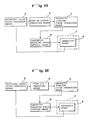
- the gearshift control apparatus of the second embodiment which controls a power transmitting means (transmission) f having a plurality of frictionally engageable gearshift means e (e.g., friction clutches) for selecting a power transmission path, includes a pressing force setting means a for releasing a force (e.g., clutch operating hydraulic pressure) to press friction members of a previous-gear-position frictionally engageable gearshift means e and setting a force to press friction members of a next-gear-position frictionally engageable gearshift means e when a gearshift is to be effected, an immediately prior condition detecting means b for detecting a condition immediately before input and output rotatable members of the frictionally engageable gearshift means e are directly coupled through frictional engagement based on the rotation of the input and output rotatable members, and a gearshift engaging force correcting means c for lowering
- the force to press the friction members of the previous-gear-position frictionally engageable gearshift means e is released by the pressing force setting means a, and a force to press the friction members of the next-gear-position frictionally engageable gearshift means e is set by the pressing force setting means a, for shifting gears from a previous gear position to a next gear position.
- the immediately prior condition detecting means b detects whether the input and output rotatable members of the frictionally engageable gearshift means e are in a condition immediately before they are directly coupled through frictional engagement, or not, based on the rotation of the input and output rotatable members.
- a step S2 seeks or detects a target gear position Sa with respect to a present gear position So from a shift map, and then a step S4 calculates an input and output rotational speed ratio e CLo of the present-gear-position gear-shift clutch and an input and output rotational speed ratio e CLa of the target-gear-position gearshift clutch. Then, a step S6 determines whether the gear positions So, Sa are equal to each other or not. The gear positions So, Sa are equal to each other if no gearshift command is issued.
- control goes to steps S8 through S12 in which a gearshift decision timer T1 is re-started, the clutch pressure P CL for the present-gear-position clutch is set to a maximum value, and a signal to keep the present gear position So is issued to the shift solenoid.
- Such a condition is shown in FIG. 10 up to a time t1.
- a gearshift command from the controller 30 and outputs from the shift solenoids 22, 23 are to keep the present gear position So. Therefore, the present gear position So and the target gear position Sa are the same as each other, and the input and output rotational speed ratio e CLo (e CLa ) of the gearshift clutch is 1.0.
- the control pressure P TH is set to a maximum value by the linear solenoid valve 56, and hence the clutch pressure P CL for the hydraulically operated clutch (gearshift means) which selects the present gear position is maximized. The force applied by the clutch piston of this clutch to press the friction discs is therefore maximized, and so is the torque CTQ transmitted by this clutch.
- step S14 which waits for the elapse of a time set by the gearshift decision timer T1 from the time the gearshift command has been issued. Control then goes from the step S14 to a step S16.
- the gearshift decision timer T1 is used to prevent gearshifts from being effected too quickly in the event that different gearshift commands are successively issued in a short period of time.
- a gearshift command for a gearshift from the third gear position to the second gear position is issued before the time set by the gearshift decision timer T1 expires after a gearshift command for a gearshift from the fourth gear position to the third gear position has been issued, then a gearshift from the fourth gear position to the second gear position is actually carried out upon elapse of the time set by the gearshift decision timer T1.
- the clutch engaging torque CTQ for the target-gear-position clutch is calculated.
- the clutch engaging torque CTQ is a torque needed to effect the desired gearshift smoothly, and can be calculated in the same manner as described above with reference to the flowchart of FIG. 5.
- control goes to a step S18 which determines whether Sa > So, i.e., an upshift is to be effected or not. If an upshift is to be effected, then control goes to a step S20 in which a shift solenoid output is switched from So to Sa for actually starting an upshift.
- a gearshift command for a gearshift from the present gear position So to the target gear position Sa is issued at the time t1
- the shift solenoid output changes from So to Sa at a time t2 upon elapse of the time set by the gearshift decision timer T1 at the step S14.
- the gearshift command is issued at the time t1
- the target gear position Sa is changed to the gear position according to the gearshift command. Therefore, the input and output rotational speed ratio e CLa of the target-gear-position (next-gear-position) clutch is changed to a value e1 for the clutch at the target gear position.
- the shift valve When the shift solenoid output changes to Sa at the time t2, the shift valve is operated to interrupt the supply of the hydraulic pressure to the hydraulically operated clutch for the preset gear position (previous gear position).
- the clutch pressure P CLo sharply drops to a preset pressure of the accumulator corresponding to this clutch.
- the hydraulic pressure or clutch oil pressure starts being supplied to the hydraulically operated clutch for the target gear position at the time t2.
- the clutch pressure P CL at this time is based on the control pressure P TH set by the linear solenoid valve 56.
- the clutch torque CTQ corresponding to the clutch pressure P CL is determined based on the pressure bearing area of the clutch piston and the return spring force as shown in FIG. 11. Therefore, the control pressure P TH may be selected to obtain the detail torque CTQ.
- the control pressure P TH may be selected to be a pressure P TH (CTQ) which produces the torque CTQ necessary for the gearshift that is calculated in the step S16.
- step S22 determines whether the target-gear-position clutch has reached a condition immediately before it is directly coupled by comparing the input and output rotational speed ratio e CLa thereof with a threshold e CIEU slightly smaller than 1.0.
- control goes to steps S24 and S26 in which a fully direct coupling decision timer T FC is re-started, and a clutch pressure P CL (CTQ) (i.e., the control pressure P TH (CTQ)) for keeping the torque CTQ calculated in the step S16 is determined.
- CQ clutch pressure
- the fully direct coupling decision timer T FC is started in a step S28, and the torque CTQ is cor rected in a step S30 and a clutch pressure P CL (CTQ) for obtaining the corrected torque CTQ is established in a step S32 until the time set by the timer T FC elapses.
- the torque correction is carried out in view of the frictional characteristics of a friction clutch (indicated by the solid lines in FIG. 13) according to which the final dynamic coefficient ⁇ o is larger than the normal dynamic coefficient ⁇ k of friction.
- the torque CTQ is corrected by multiplying the torque calculated in the step S16 by Tk/To so that the difference between the torques produced due to the different coefficients of friction (i.e., the difference between the torques Tk, To in FIG. 13) is canceled out.
- the clutch pressure P CL is lowered as indicated by the solid line from a time t4 when the condition e CLa > e CIEU is reached to a time t6 when the time set by the fully direct coupling decision timer T FC expires. Consequently, even if this clutch is in a condition immediately before it is directly coupled, and the coefficient of friction becomes the larger final dynamic coefficient ⁇ o of friction, the pressing force on the discs of this clutch is lowered to cancel out the increased coefficient of friction, and hence the clutch engaging torque for this clutch is not increased. Accordingly, an abrupt increase in the clutch engaging torque is prevented at the time the gearshift is finished, and the gearshift is smoothly effected.
- FIG. 10 shows how the engine rotational speed Ne and the acceleration (deceleration) G applied to the vehicle body vary during the gearshift.
- the solid-line curves representing Ne and G in FIG. 10 indicate that the engine speed Ne and the acceleration (deceleration) G vary relatively smoothly, and hence the gearshift is carried out smoothly. If the correction in the step S30 were not carried out and the control pressure P TH were established as indicated by the broken line in FIG. 10, then the torque for engaging the target-gear-position clutch would be abruptly increased immediately before it is directly coupled, so that the engine rotational speed Ne and the acceleration (deceleration) G would vary sharply as indicated by the broken lines, resulting in a gearshift shock.
- the torque may be corrected on a real-time basis in a manner to correspond to a torque variation immediately before the clutch is directly coupled.
- control goes from the step S28 to a step S34 in which the target gear position Sa changes to the present gear position So.
- control goes from the step S6 to the steps S8 through S12, so that the clutch pressure P CL is maximized and the target gear position So which has changed is maintained as it is.
- the above control process is directed to an upshift. However, the same control process is executed to effect a downshift.
- step S40 in which the solenoid output changes from So to Sa to start effecting the downshift.
- the shift solenoid output changes from So to Sa after elapse of the time set by the gearshift decision timer T1 in the step S14 from the time when the gearshift command for the gearshift from the present gear position So to the target gear position Sa has been issued.
- the shift valve is operated to cut off the supply the hydraulic pressure to the present-gear-position (previous-gear-position) hydraulically operated clutch whose clutch pressure P CLo then drops sharply, and the hydraulic pressure starts being supplied to the target-gear-position hydraulically operated clutch.
- a control pressure P TH (CTQ) for producing a torque DTQ higher than the calculated torque CTQ is established until the clutch starts being engaged (i.e., until the input and output rotational speed ratio e CLo of the present-gear-position clutch starts to vary).
- the control pressure P TH (CTQ) for producing the calculated torque CTQ is established.
- step S42 determines whether the target-gear-position clutch has reached a condition immediately before it is directly coupled by comparing the input and output rotational speed ratio e CLa thereof with a threshold e CIED slightly larger than 1.0.
- the fully direct coupling decision timer T FC is started in a step S48, and the torque CTQ is corrected in a step S50 and a clutch pressure P CL (CTQ) for obtaining the corrected torque CTQ is established in a step S52 until the time set by the timer T FC elapses.
- the torque CTQ is corrected by multiplying the torque calculated in the step S16 by Tk/To so that the difference between the torques produced due to the different coefficients ⁇ k, ⁇ o of friction (i.e., the difference between the torques Tk, To in FIG. 13) is canceled out.
- the clutch pressure P CL is lowered from the time when the condition e CLa ⁇ e CIED is reached to the time when the time set by the fully direct coupling decision timer T FC expires. Consequently, even if this clutch is in a condition immediately before it is directly coupled, and the coefficient of friction becomes the larger final dynamic coefficient ⁇ o of friction, the clutch engaging torque for this clutch is not increased. Accordingly, an abrupt increase in the clutch engaging torque is prevented at the time the gearshift is finished, and the gearshift is smoothly effected.
- control goes from the step S48 to a step S54 in which the target gear position Sa changes to the present gear position So.
- control goes from the step S6 to the steps S8 through S12, so that the clutch pressure P CL is maximized and the target gear position So which has changed is maintained as it is.
- the gearshift control apparatus of the third embodiment which controls a power transmitting means (transmission) f having a plurality of gearshift means e for selecting a power transmission path, includes a gearshift engaging force setting means a for releasing an engaging force of a previous-gear-position gearshift means e and setting an engaging force for a next-gear-position gearshift means e, a rotational speed ratio detecting means g for detecting the input and output rotational speed ratio of the gearshift means e, a rate-of-change comparing means h for determining the rate of change of the input and output rotational speed ratio of the gearshift means e as detected by the rotational speed ratio detecting means g and comparing the determined rate of change with a reference rate of change to determine the difference therebetween, and a gearshift engaging force correcting means c for correcting the engaging force for the next-gear-position gearshift means e
- the engaging force of the previous-gear-position gearshift means e is released and an engaging force for the next-gear-position gearshift means e is set by the gearshift engaging force setting means a, for making a gearshift from the previous gear position to the next gear position.
- the input and output rotational speed ratio of the next-gear-position gearshift means e is detected by the rotational speed ratio detecting means g, and the rate of change of the detected input and output rotational speed ratio is compared with the reference rate of change, thus determining the difference between the compared rates of change.
- the gearshift engaging force correcting means c corrects the engaging force for the next-gear-position gearshift means as set by the gearshift engaging force setting means a so that the rate of change of the input and output rotational speed ratio of the next-gear-position gearshift means becomes closer to the reference rate of change.
- the time required for the gearshift and the rate of change of the ratio between the rotational speeds of the input and output members of the gearshift means are set to desired values, with the result the gearshift can be smoothly carried out without a gearshift shock.
- FIGS. 17A and 17B Such a condition is shown in FIGS. 17A and 17B up to a time t1.
- a gearshift command from the controller 30 and outputs from the shift solenoids 22, 23 are to keep the present gear position So. Therefore, the present gear position So and the target gear position Sa are the same as each other, and the input and output rotational speed ratio e CLo (e CLa ) of the gearshift clutch is 1.0.
- the control pressure P TH is set to a maximum value by the linear solenoid valve 56, and hence the clutch pressure P CL for the hydraulically operated clutch (gearshift means) which selects the present gear position is maximized.
- the timer T1 is used to prevent gearshifts from being effected too quickly in the event that different gearshift commands are successively issued in a short period of time. For example, if a gearshift command for a gearshift from the third gear position to the second gear position is issued before the time set by the gearshift decision timer T1 expires after a gearshift command for a gearshift from the fourth gear position to the third gear position has been issued, then a gearshift from the fourth gear position to the second gear position is actually carried out upon elapse of the time set by the gearshift decision timer T1.
- step S20 an initial value P CL (So, Sa) for the clutch pressure P CL which has been set that corresponds to the gearshift (from the present gear position So to the target gear position Sa) at this time is read.
- step S22 a time interval T FBI (So, Sa) between the control cycles of the present control sequence, which has been set that corresponds to the present gearshift, is read.
- step S24 a reference gearshift time T REF (So, Sa), which has been set that corresponds to the present gearshift, is read.
- control goes to a step S30 in FIG. 15B which determines whether the input and output rotational speed ratio e CLo of the present-gear-position clutch remains substantially 1.0 or not.
- the rotational speed ratio e CLo is 1.0.
- the rotational speed ratio e CLo deviates from 1.0 (specifically, it increases from 1.0 for an upshift and decreases from 1.0 for a downshift). It can thus be determined whether the gearshift has actually been started by determining the value of the input and output rotational speed ratio e CLo .
- the gearshift is actually started after a certain time lag even if the shift solenoid output has changed to Sa. Accordingly, the rotational speed ratio e CLo remains 1.0 during such a time lag. If e CLo ⁇ 1.0, then the gearshift command for the target gear position Sa is kept in a step S58, and the present control cycle is brought to an end.
- a step S32 determines whether the gearshift commands dictates an upshift or not (i.e., if Sa > So).
- step S34 compares the rate of change ⁇ e CLa of the input and output rotational speed ratio e CLa of the target-gear-position clutch with an upper limit value (DER + ⁇ ) for the reference rate of change DER. If ⁇ e CLa > (DER + ⁇ ), then the preset clutch pressure P CL is reduced in a step S40 by subtracting a predetermined pressure P FB (which is of a small value) from the preset clutch pressure P CL as shown in FIG. 16A. However, rather than subtracting the constant value from the preset clutch pressure P CL , a corrective amount which is proportional to the difference between the rate of change ⁇ e CLa and the reference rate of change DER may be subtracted from the preset clutch pressure P CL .
- the input and output rotational speed ratio e CLa of the target-gear-position clutch varies from e1 ( ⁇ 1.0) to 1.0.
- the range (1.0 - e1) over which the ratio e CLa varies is given by: (Go - Ga)/Go and is of a positive value. Since the reference gearshift time TREF required for effecting the gearshift with a good driver's feeling has been read in the step S24, the reference rate of change DER of the input and output rotational speed ratio of the target-gear-position clutch for the gearshift is determined by the equation (1) above.
- the manner in which the ratio e CLa varies based on the reference rate of change DER is indicated by the broken line in FIG. 17A.
- the ratio e CLa varies from e1 to 1.0 during the reference gearshift time TREF from the time t3.
- the gradient of the e CLa curve during the reference gearshift time T REF represents the reference rate of change DER.
- the rotational speed ratio e CLa actually varies as indicated by the solid line.
- the rotational speed ratio e CLa initially varies at a rate smaller than the reference rate of change DER.
- the clutch pressure P CL is increased in the step S38.
- the clutch pressure P CL is corrected by the linear solenoid valve 56 to correct the clutch pressure P CL .
- step S42 compares the rate of change ⁇ e CLa of the input and output rotational speed ratio e CLa of the target- gear-position clutch with a lower limit value (DER - ⁇ ) for the reference rate of change DER. If ⁇ e CLa ⁇ (DER - ⁇ ), then the preset clutch pressure P CL is reduced in a step S44 by subtracting the predetermined pressure P FB from the preset clutch pressure PCL as shown in FIG. 16A.
- step S46 If ⁇ e CLa ⁇ (DER - ⁇ ), then the rate of change ⁇ e CLa is compared with the upper limit (DER + ⁇ ) for the reference rate of change in a step S46. If ⁇ e CLa > (DER + ⁇ ), then control goes to a step S48 in which the clutch pressure P CL is increased by adding the prescribed pressure P FB to the preset clutch pressure P CL as shown in FIG. 16B.
- the input and output rotational speed ratio e CLa of the target-gear-position clutch varies from e2 (> 1.0) to 1.0.
- the range (1.0 - e2) over which the ratio e CLa varies is given by: (Go - Ga)/Go and is of a negative value.
- the reference rate of change DER of the input and output rotational speed ratio of the target-gear-position clutch for this gearshift is determined by the equation (1) above.
- the manner in which the ratio e CLa varies based on the reference rate of change DER is indicated by the broken line in FIG. 17B.
- the ratio e CLa varies from e2 to 1.0 during the reference gearshift time T REF from the time t3.
- the gradient of the e CLa curve dur ing the reference gearshift time T REF represents the reference rate of change DER. Since the reference rate of change DER is of a negative value, the gradient is downward to the right.
- the rotational speed ratio e CLa actually varies as indicated by the solid line.
- the rotational speed ratio e CLa initially varies at a rate smaller (sharper) than the reference rate of change DER.
- ⁇ e CLa ⁇ (DER - ⁇ )
- the clutch pressure P CL is reduced in the step S44.
- the clutch pressure P CL is progressively decreased from the initial value set at the time t2 from the time t3, and the rate of change ⁇ e CLa of the rotational speed ratio e CLa is gradually increased (less sharply).
- step S50 the control process after the step S50 is also effected. This will not be described in detail as it is the same as the process for the upshift.
- the gearshift control processes for an upshift and a downshift are effected as described above. As shown in FIG. 2, the gearshift modes further include power-on and power-off modes. Therefore, the gearshift control processes for these modes will also be described below.
- a reference gearshift time T REF is established based on the full throttle valve opening when the difference between the input and output rotational speeds of the target-gear-position clutch is the greatest in a gearshift. Since the reference gearshift time T REF is selected in order to suppress a gear-shift shock upon the full throttle valve opening when the gearshift shock tends to be maximum, gearshifts at other throttle valve openings can be effected with smaller gear-shift shocks, and hence no gearshift shock problem is experienced.
- the target-gear-position clutch may remain disengaged until the input and output rotational speeds thereof become synchronized, but the gearshift time needed may then be too long. Conversely, if the target-gear-position clutch is engaged too early, then the rotational speed of the clutch may be varied violently, developing noise and gearshift shocks. In this mode, therefore, an appropriate reference gearshift time TREF is established to cause the rotational speed ratio to vary smoothly for smooth gearshifts.
- the target-gear-position clutch In the power-on/downshift mode (SYD mode), the target-gear-position clutch is engaged when the input and output rotational speeds thereof are synchronized, and until the clutch is engaged, the rotational speed of the clutch should be varied according to an increase in the engine rotational speed. If a downshift from the fourth gear position to the second gear position is to be effected, for example, it takes time for the engine rotational speed to increase, and the gearshift time may be too long. In this case, the gearshift is controlled based on the reference gearshift time T REF thereby to shorten the gearshift time, so that the gearshift may be controlled without making the driver feel uneasy or embarrassed.
- the control process which is the reversal of the control process for the power-on/upshift mode may be carried out.
- IPD mode since it is a gearshift which expects engine braking, it is preferable to establish a relatively short reference gearshift time T REF for early engine braking.
- EPD mode it is preferable to establish a relatively long reference gearshift time T REF for effecting a gearshift with a small gearshift shock.
- the gearshift control apparatus of the third embodiment which controls a power transmitting means (transmission) f having a plurality of gearshift means e for selecting a power transmission path, includes a gearshift engaging force setting means a for releasing an engaging force of a previous-gear-position gearshift means e and setting an engaging force for a next-gear-position gearshift means e when a gearshift is effected in either the power-off/downshift mode or the power-on/upshift mode, a rotational speed ratio detecting means g for detecting the input and output rotational speed ratio of the gearshift means e, a time lag measuring means d for measuring, based on a signal from the rotational speed detecting means g, a time lag from the time when an output is issued to effect the gearshift in either one of the modes to the time when the input and output rotational speed ratio of the next-gear-position gear
- the engaging force of the previous-gear-position gearshift means e is released and an engaging force for the next-gear-position gearshift means e is set by the gearshift engaging force setting means a, for making a gearshift from the previous gear position to the next gear position.
- the engaging force in the time lag is corrected by the gearshift engaging force correcting means c.
- the engaging force is corrected so that the time lag becomes closer to the reference value. For example, if the time lag is larger than the reference value, then the engaging force is set to a larger value to shorten the time lag. Therefore, even when the time lag varies depending on the characteristics of the individual gearshift means and the oil temperature, the time lag is corrected so as to becomes closer to the reference value each time a gearshift is effected, with the result that desired gearshift characteristics can be achieved.
- a step S2 seeks or detects a target gear position Sa with respect to a present gear position So from a shift map, and a step S4 determines whether the gear positions So, Sa are equal to each other or not.
- the gear positions So, Sa are equal to each other if no gearshift command is issued.
- control goes to steps S6 through S12 in which a gearshift decision timer T1 is re-started, the torque CTQ transmitted by the present-gear-position clutch is set to a maximum value, the value of a time lag counter TLAG is set to zero, and tne present gear position So is maintained as it is.
- a current to be supplied to the linear solenoid valve 56, which is required to produce the maximum torque CTQ, is determined in a step S40.
- the current is then issued in a step S42 to establish a control pressure P TH to obtain the torque CTQ.
- Such a condition is shown in FIG. 20A up to a time t1.
- the control pressure P TH is set to a maximum value by the linear solenoid valve 56, and hence the clutch pressure P CL for the hydraulically operated clutch (gearshift means) which selects the present gear position is maximized. The torque CTQ transmitted by this clutch is maximized.
- step S14 which waits for the elapse of a time set by the gearshift decision timer T1 from the time the gearshift command has been issued. Control then goes from the step S14 to a step S16.
- the gearshift decision timer T1 is used to prevent gearshifts from being effected too quickly in the event that different gearshift commands are successively issued in a short period of time.
- a gearshift command for a gearshift from the third gear position to the second gear position is issued before the time set by the gearshift decision timer T1 expires after a gearshift command for a gearshift from the fourth gear position to the third gear position has been issued, then a gearshift from the fourth gear position to the second gear position is actually carried out upon elapse of the time set by the gearshift decision timer T1.
- the step S16 determines whether Sa > So, i.e., an upshift is to be effected or not. If an upshift is to be effected, then control goes to the flowchart shown in FIG. 19B. The flowchart of FIG. 19B will be described later on. If Sa ⁇ So and hence a downshift is to be effected, control goes to a step S18 which determines whether the mode is the power-on mode or not. If the power-on mode, then control goes to a step S20 in which the power-on/downshit mode is processed. Since the power-off/downshift mode is to be processed here, the control process in the step S20 will not be described. When a gearshift command is issued to effect a gearshift, the present gear position So is the previous gear position, and the target gear position Sa is the next gear position.
- control goes to a step S22 in which the shift solenoid is operated to effect a gear shift from So to Sa.
- a gearshift command for a gearshift from the present gear position So to the target gear position Sa is issued at the time t1
- the shift solenoid output changes from So to Sa at a time t2 upon elapse of the time set by the gearshift decision timer T1 at the step S14.
- the gearshift command is issued at the time t1
- the target gear position Sa is changed to the gear position according to the gearshift command. Therefore, the input and output rotational speed ratio e CLa of the target-gear-position (next-gear-position) clutch is changed to a value e1 for the clutch at the target gear position.
- a step S24 determines whether the input and output rotational speed ratio e CLo of the present-gear-position clutch is smaller than a gearshift start decision value e CISD or not. Even if the shift solenoid output changes to Sa, the present-gear-position clutch is not immediately disengaged, but there is a certain time lag before it is actually disengaged. Therefore, the condition e CLo ⁇ e CISD remains initially. In this case, the time lag starts being measured by the time lag counter TLAG at a step S26. In a step S28, a rising clutch torque DTQ is set to a rising clutch torque DTQ (Sa, So) which is stored according to a gearshift pattern.
- the shift valve When the shift solenoid output changes to Sa at the time t2, the shift valve is operated to interrupt the supply of the hydraulic pressure to the hydraulically operated clutch for the preset gear position (previous gear position).
- the clutch pressure P CLo sharply drops to a preset pressure of the accumulator corresponding to this clutch.
- the hydraulic pressure or clutch oil pressure starts being supplied to the hydraulically operated clutch for the target gear position at the time t2.
- the hydraulic pressure supplied at this time is the hydraulic pressure P CL (DTQ) corresponding to the rising clutch torque DTQ.
- the current is determined and issued in the steps S40, S42 to produce such hydraulic pressure.
- the control pressure P TH is set to the corresponding hydraulic pressure P TH (DTQ) by the linear solenoid valve 56.
- the clutch pressure P CL is of a low value corresponding to the resistance presented by the pipe coupled to the hydraulic chamber of the target-gear-position clutch up to a time t3 until the pipe is filled with the clutch oil and the clutch is completely moved an ineffective stroke of the piston of the clutch.
- This time interval (from t2 to t3) is referred to as a "filling time".
- the clutch pressure P CL is very low during the filling time.
- the clutch pressure P CL rises to a pressure P CL (DTQ) corresponding to the control pressure P TH (DTQ).
- the orifice control valve is operated to discharge the hydraulic pressure from the present-gear-position clutch to drain until the hydraulic pressure P CLo for this clutch is reduced to zero whereupon the present-gear-position clutch is fully disengaged.
- the target-gear-position clutch starts being engaged to start the gearshift actually.
- the input and output rotational speed ratio e CLa of the target-gear-position clutch decreases from e1 to 1.0, and the input and output rotational speed ratio e CLo of the present-gear-position clutch is reduced from 1.0. Therefore, if e CLo ⁇ e CISD at a time t4 in the step S24, then the time lag TLAG from the time t2 when the shift solenoid output changes to the target gear position Sa to the time t4 when e CLo ⁇ e CISD is read from the value measured by the time lag counter, and then control goes to a step S30.
- FIG. 20A shows that the rising torque DTQ thus set is small, and the control pressure P TH and the clutch pres sure P CL are low, with the filling time being long. Since the clutch pressure P CL is low, the present-gear-position clutch slips before the target-gear-position clutch starts being engaged, with the result that the input and output rotational speed ratio e CLo of the present-gear-position clutch becomes larger than 1.0. Therefore, the input and output rotational speed ratio e CLa of the target-gear-position clutch is also larger than 1.0.
- the rising torque DTQ is increased if the rising torque DTQ is small and the time lag TLAG is longer than the reference value DLAGD, and reduced otherwise.
- the rising torque DTQ thus corrected is stored as a new rising torque.
- a torque CTQ required to engage the target-gear-position clutch is calculated, and a current for the linear solenoid valve 56 is determined and issued in order to produce the calculated torque CTQ in the steps S40, S42.
- the control pressure P TH is set to a hydraulic pressure P TH (CTQ) corresponding to the torque CTQ from the time t4 (time t14 in FIG. 20B) for a gearshift.
- the torque CTQ in the step S34 is calculated in the same routine as the routine of FIG. 5.
- the rising torque DTQ is corrected when it is small and the time lag is long (FIG. 20A). Correction of the rising torque DTQ when it is too large will be described below with reference to FIG. 21.
- a maximum torque is set as the rising torque DTQ.
- a gearshift command is issued at a time t21, and the shift solenoid output changes from So to Sa at a time t22 after elapse of the time set by the gearshift decision timer T1.
- the hydraulic pressure supplied to the target-gear-position clutch becomes a hydraulic pressure corresponding to the rising torque DTQ. Since the torque DTQ is of the maximum level, the supplied hydraulic pressure (clutch pressure) P CL is also maximized, and the filling time is considerably shortened as shown.
- the pressure P CLo for the present-gear-position clutch is reduced to zero, and the clutch pressure P CLa for the target-gear-position clutch starts to rise quickly up to a value corresponding to the torque DTQ, i.e., the maximum hydraulic pressure.
- the target-gear-position clutch now starts being engaged. Inasmuch as the clutch pressure P CLa increases quickly, the target-gear-position clutch is engaged quickly, and the input and output rotational speed ratio e CLa thereof varies quickly, producing a gearshift shock.
- the filling time is short and the time lag TLAG is also short, and the time lag difference Ao calculated in the step S30 is negative.
- the rising torque DTQ is corrected so as to be smaller based on the difference Ao.
- the filling time becomes longer, and the time lag TLAG becomes closer to the reference value, reducing a gearshift shock.
- the rising torque DTQ is set as a constant value for each gearshift.
- the rising torque DTQ may be of such variable characteristics that it approaches the subsequent rising torque DTQ, from the time (t12, in FIG. 20B) when the shift solenoid output changes to the time (time t14 in FIG. 20B) when the clutch begins to be engaged.
- the control pressure P TH is gradually lowered from the time t12 to the time t14 so as to become closer to the pressure P TH (CTQ) after the time t14.
- a step S50 determines whether the mode is the power-on mode or not. If it is the power-off mode, control goes to a step S52 in which the power-on/upshift mode is processed.
- the power-on/upshift mode will not be described in detail as it has no direct bearing on the routine of FIG. 19B.
- step S54 determines whether the input and output rotational speed ratio e CLo of the present-gear-position clutch is smaller than a gearshift start decision value e CISU or not. If the gearshift is an upshift, the input and output rotational speed ratio e CLo of the target-gear-position clutch increases from 1.0. Therefore, the step S56 determines whether the clutch actually starts being engaged or not.
- the time lag TLAG is measured by the time lag counter TLAG in a step S58, and a stored rising torque DTQ is set in a step S60.
- the rising torque thus corrected becomes closer to the reference time lag.
- the torque CTQ for engaging the target-gear-position clutch is calculated in a step S66, and a control pressure P TH is established to produce the calculated torque CTQ.
- a clutch engaging torque which will be required by a hydraulically operated clutch to be engaged for a gearshift is preset.
- a hydraulic pressure required to obtain the clutch engaging torque while the hydraulically operated clutch is at rest is calculated.
- a corrective action is effected by, for example, subtracting from the hydraulic pressure a centrifugal hydraulic pressure which will be developed in the hydraulically operated clutch by the rotation thereof in the gearshift, thus determining a hydraulic pressure to operate the hydraulically operated clutch.
Applications Claiming Priority (8)
| Application Number | Priority Date | Filing Date | Title |
|---|---|---|---|
| JP19540988A JPH0246364A (ja) | 1988-08-05 | 1988-08-05 | 変速用油圧作動クラッチの作動用ライン圧設定装置 |
| JP195409/88 | 1988-08-05 | ||
| JP196657/88 | 1988-08-06 | ||
| JP63196657A JPH0246360A (ja) | 1988-08-06 | 1988-08-06 | 自動変速機の変速制御装置 |
| JP63198151A JPH0246363A (ja) | 1988-08-09 | 1988-08-09 | 自動変速機の変速制御装置 |
| JP19815288A JPH0246356A (ja) | 1988-08-09 | 1988-08-09 | 自動変速機の変速制御装置 |
| JP198151/88 | 1988-08-09 | ||
| JP198152/88 | 1988-08-09 |
Publications (3)
| Publication Number | Publication Date |
|---|---|
| EP0353771A2 true EP0353771A2 (fr) | 1990-02-07 |
| EP0353771A3 EP0353771A3 (fr) | 1991-02-06 |
| EP0353771B1 EP0353771B1 (fr) | 1994-05-18 |
Family
ID=27475760
Family Applications (1)
| Application Number | Title | Priority Date | Filing Date |
|---|---|---|---|
| EP89114456A Expired - Lifetime EP0353771B1 (fr) | 1988-08-05 | 1989-08-04 | Dispositif pour commander des changements de rapports dans des transmissions automatiques |
Country Status (3)
| Country | Link |
|---|---|
| US (1) | US5128868A (fr) |
| EP (1) | EP0353771B1 (fr) |
| DE (1) | DE68915361T2 (fr) |
Cited By (3)
| Publication number | Priority date | Publication date | Assignee | Title |
|---|---|---|---|---|
| EP0435374A2 (fr) * | 1989-12-26 | 1991-07-03 | General Motors Corporation | Méthode pour commander un changement de vitesse dans une transmission automatique |
| EP0698754A2 (fr) | 1994-08-23 | 1996-02-28 | Honda Giken Kogyo Kabushiki Kaisha | Système de commande de transmission automatique pour véhicule |
| EP0780602A2 (fr) * | 1995-12-19 | 1997-06-25 | Aisin Aw Co., Ltd. | Dispositif de commande de pression hydraulique pour la transmission automatique d'un véhicule |
Families Citing this family (12)
| Publication number | Priority date | Publication date | Assignee | Title |
|---|---|---|---|---|
| JP2811912B2 (ja) * | 1990-05-18 | 1998-10-15 | トヨタ自動車株式会社 | 車両用自動変速機の制御装置 |
| DE4100372A1 (de) * | 1991-01-09 | 1992-07-16 | Fichtel & Sachs Ag | Anordnung zur regelung des schlupfs einer automatisierten reibungskupplung |
| DE59108372D1 (de) * | 1991-09-11 | 1997-01-02 | Siemens Ag | Steuerung für einen Kraftfahrzeugantrieb mit einem automatischen Getriebe |
| JP3242494B2 (ja) * | 1993-06-03 | 2001-12-25 | トヨタ自動車株式会社 | 自動変速機の変速制御装置 |
| JPH0872589A (ja) * | 1994-09-02 | 1996-03-19 | Hitachi Ltd | パワートレイン制御装置及び制御方法 |
| JP2928734B2 (ja) * | 1994-10-31 | 1999-08-03 | 本田技研工業株式会社 | 車両用クラッチ機構の作動状態判定装置 |
| JP3364738B2 (ja) * | 1996-07-31 | 2003-01-08 | ジヤトコ株式会社 | 自動変速機のアップシフト制御装置 |
| US7013250B2 (en) * | 2000-03-14 | 2006-03-14 | Honda Giken Kogyo Kabushiki Kaisha | Simulator for automatic vehicle transmission controllers |
| US6666794B2 (en) * | 2000-09-05 | 2003-12-23 | Unisia Jecs Corporation | Apparatus and method for controlling automatic transmission |
| EP1353095A1 (fr) * | 2002-04-10 | 2003-10-15 | Van Doorne's Transmissie B.V. | Méthode de commande pour une transmission automatique |
| JP3784353B2 (ja) * | 2002-08-28 | 2006-06-07 | ジヤトコ株式会社 | 車両用変速機の油圧制御装置 |
| US9014928B2 (en) * | 2013-02-14 | 2015-04-21 | Ford Global Technologies, Llc | Transmission gearshift control |
Citations (6)
| Publication number | Priority date | Publication date | Assignee | Title |
|---|---|---|---|---|
| DE3205767A1 (de) * | 1982-02-18 | 1983-08-25 | Robert Bosch Gmbh, 7000 Stuttgart | Einrichtung zum einstellen des druckes des arbeitsmediums in automatischen stufengetrieben |
| EP0182376A2 (fr) * | 1984-11-22 | 1986-05-28 | Nissan Motor Co., Ltd. | Dispositif de commande de changement de rapport dans une transmission automatique |
| US4653350A (en) * | 1985-11-29 | 1987-03-31 | General Motors Corporation | Adaptive direct pressure shift control for a motor vehicle transmission |
| EP0235892A1 (fr) * | 1986-02-12 | 1987-09-09 | General Motors Corporation | Rétrogradage sous charge d'un embrayage à l'autre dans une transmission automatique de véhicule à moteur |
| JPS6353349A (ja) * | 1986-08-20 | 1988-03-07 | Aisin Warner Ltd | 電子制御式自動変速機 |
| FR2610371A1 (fr) * | 1987-02-02 | 1988-08-05 | Renault Vehicules Ind | Dispositif et procede electronique de commande d'un groupe motopropulseur lors des passages des rapports sous couple |
Family Cites Families (8)
| Publication number | Priority date | Publication date | Assignee | Title |
|---|---|---|---|---|
| JPS60151444A (ja) * | 1984-01-13 | 1985-08-09 | Nissan Motor Co Ltd | 自動変速機の変速制御装置 |
| JPS60201152A (ja) * | 1984-03-27 | 1985-10-11 | Mitsubishi Motors Corp | 車両用自動変速機 |
| JPS60245863A (ja) * | 1984-05-22 | 1985-12-05 | Nissan Motor Co Ltd | 自動変速機のクラツチ圧制御装置 |
| JPS6241459A (ja) * | 1985-08-16 | 1987-02-23 | Nissan Motor Co Ltd | 自動変速機の変速シヨツク軽減装置 |
| JPH0781594B2 (ja) * | 1985-08-31 | 1995-08-30 | 三菱自動車工業株式会社 | 動力伝達装置 |
| US4707789A (en) * | 1985-11-29 | 1987-11-17 | General Motors Corporation | Adaptive direct pressure shift control for a motor vehicle transmission |
| JPS62151656A (ja) * | 1985-12-24 | 1987-07-06 | Toyota Motor Corp | 車両用自動変速機のフエイルセ−フ装置 |
| JPS62159842A (ja) * | 1986-01-07 | 1987-07-15 | Toyota Motor Corp | 自動変速機の油圧制御装置 |
-
1989
- 1989-08-04 EP EP89114456A patent/EP0353771B1/fr not_active Expired - Lifetime
- 1989-08-04 DE DE68915361T patent/DE68915361T2/de not_active Expired - Lifetime
- 1989-08-04 US US07/389,851 patent/US5128868A/en not_active Expired - Lifetime
Patent Citations (6)
| Publication number | Priority date | Publication date | Assignee | Title |
|---|---|---|---|---|
| DE3205767A1 (de) * | 1982-02-18 | 1983-08-25 | Robert Bosch Gmbh, 7000 Stuttgart | Einrichtung zum einstellen des druckes des arbeitsmediums in automatischen stufengetrieben |
| EP0182376A2 (fr) * | 1984-11-22 | 1986-05-28 | Nissan Motor Co., Ltd. | Dispositif de commande de changement de rapport dans une transmission automatique |
| US4653350A (en) * | 1985-11-29 | 1987-03-31 | General Motors Corporation | Adaptive direct pressure shift control for a motor vehicle transmission |
| EP0235892A1 (fr) * | 1986-02-12 | 1987-09-09 | General Motors Corporation | Rétrogradage sous charge d'un embrayage à l'autre dans une transmission automatique de véhicule à moteur |
| JPS6353349A (ja) * | 1986-08-20 | 1988-03-07 | Aisin Warner Ltd | 電子制御式自動変速機 |
| FR2610371A1 (fr) * | 1987-02-02 | 1988-08-05 | Renault Vehicules Ind | Dispositif et procede electronique de commande d'un groupe motopropulseur lors des passages des rapports sous couple |
Non-Patent Citations (1)
| Title |
|---|
| PATENT ABSTRACTS OF JAPAN vol. 12, no. 272 (M-724)(3119) 28 July 1988, & JP-A-63 53349 (AISIN WARNER) 07 March 1988, * |
Cited By (7)
| Publication number | Priority date | Publication date | Assignee | Title |
|---|---|---|---|---|
| EP0435374A2 (fr) * | 1989-12-26 | 1991-07-03 | General Motors Corporation | Méthode pour commander un changement de vitesse dans une transmission automatique |
| EP0435374A3 (en) * | 1989-12-26 | 1992-06-24 | General Motors Corporation | Method of controlling gear change in an automatic transmission |
| EP0698754A2 (fr) | 1994-08-23 | 1996-02-28 | Honda Giken Kogyo Kabushiki Kaisha | Système de commande de transmission automatique pour véhicule |
| EP0698754A3 (fr) * | 1994-08-23 | 1997-05-14 | Honda Motor Co Ltd | Système de commande de transmission automatique pour véhicule |
| US5827152A (en) * | 1994-08-23 | 1998-10-27 | Honda Giken Kogyo Kabushiki Kaisha | Control system for automtic transmission for vehicle |
| EP0780602A2 (fr) * | 1995-12-19 | 1997-06-25 | Aisin Aw Co., Ltd. | Dispositif de commande de pression hydraulique pour la transmission automatique d'un véhicule |
| EP0780602A3 (fr) * | 1995-12-19 | 1998-12-09 | Aisin Aw Co., Ltd. | Dispositif de commande de pression hydraulique pour la transmission automatique d'un véhicule |
Also Published As
| Publication number | Publication date |
|---|---|
| US5128868A (en) | 1992-07-07 |
| DE68915361D1 (de) | 1994-06-23 |
| EP0353771A3 (fr) | 1991-02-06 |
| EP0353771B1 (fr) | 1994-05-18 |
| DE68915361T2 (de) | 1994-08-25 |
Similar Documents
| Publication | Publication Date | Title |
|---|---|---|
| EP0354493A2 (fr) | Dispositif pour commander des changements de rapports des transmissions automatiques | |
| EP0353771A2 (fr) | Dispositif pour commander des changements de rapports dans des transmissions automatiques | |
| US5480363A (en) | Apparatus for controlling slip of lock-up clutch on motor vehicle during deceleration of the vehicle | |
| EP0331523B1 (fr) | Procédé pour déterminer et empêcher l'emballement d'un moteur pendant le changement de vitesse d'une transmission d'automobile automatique | |
| EP0331522B1 (fr) | Dispositif et procédé pour commander le fonctionnement d'un embrayage hydraulique dans une transmission automatique | |
| US5954776A (en) | Hydraulic control apparatus of automatic transmission | |
| US4955257A (en) | Method of controlling shifts in an automatic transmission | |
| US4870581A (en) | Electronically controlled automatic transmission | |
| US5012699A (en) | Apparatus for controlling gearshifts in automatic transmission | |
| JPS6321062B2 (fr) | ||
| US5069085A (en) | Shift control system for automatic power transmission with enhanced shifting transition characteristics | |
| US5125294A (en) | Method of controlling speed range shifting in an automatic transmission | |
| US6638196B2 (en) | Shift control apparatus of automatic transmissions | |
| JPH0473031B2 (fr) | ||
| KR20020022017A (ko) | 자동 변속기용 변속 제어 시스템 | |
| JP3498473B2 (ja) | 車両用自動変速機の制御装置 | |
| JPH0428564B2 (fr) | ||
| JPH10181386A (ja) | 自動変速機の変速制御装置 | |
| JPH0559293B2 (fr) | ||
| JPH0557468B2 (fr) | ||
| JP2920232B2 (ja) | 自動変速機の変速ショック軽減装置 | |
| KR100285477B1 (ko) | 자동변속기의 파워 온 다운 쉬프트시 동기 제어방법 | |
| JPH11108168A (ja) | 自動変速機の油圧制御装置 | |
| JPH0842686A (ja) | 自動変速機のトルクコンバータクラッチ制御装置 | |
| JP2958980B2 (ja) | 自動変速機のライン油圧制御方法 |
Legal Events
| Date | Code | Title | Description |
|---|---|---|---|
| PUAI | Public reference made under article 153(3) epc to a published international application that has entered the european phase |
Free format text: ORIGINAL CODE: 0009012 |
|
| AK | Designated contracting states |
Kind code of ref document: A2 Designated state(s): DE FR GB |
|
| PUAL | Search report despatched |
Free format text: ORIGINAL CODE: 0009013 |
|
| AK | Designated contracting states |
Kind code of ref document: A3 Designated state(s): DE FR GB |
|
| 17P | Request for examination filed |
Effective date: 19910410 |
|
| 17Q | First examination report despatched |
Effective date: 19921216 |
|
| GRAA | (expected) grant |
Free format text: ORIGINAL CODE: 0009210 |
|
| AK | Designated contracting states |
Kind code of ref document: B1 Designated state(s): DE FR GB |
|
| REF | Corresponds to: |
Ref document number: 68915361 Country of ref document: DE Date of ref document: 19940623 |
|
| ET | Fr: translation filed | ||
| PLBE | No opposition filed within time limit |
Free format text: ORIGINAL CODE: 0009261 |
|
| STAA | Information on the status of an ep patent application or granted ep patent |
Free format text: STATUS: NO OPPOSITION FILED WITHIN TIME LIMIT |
|
| PG25 | Lapsed in a contracting state [announced via postgrant information from national office to epo] |
Ref country code: FR Effective date: 19950428 |
|
| 26N | No opposition filed | ||
| REG | Reference to a national code |
Ref country code: FR Ref legal event code: ST |
|
| REG | Reference to a national code |
Ref country code: GB Ref legal event code: IF02 |
|
| PGFP | Annual fee paid to national office [announced via postgrant information from national office to epo] |
Ref country code: GB Payment date: 20050803 Year of fee payment: 17 |
|
| GBPC | Gb: european patent ceased through non-payment of renewal fee |
Effective date: 20060804 |
|
| PG25 | Lapsed in a contracting state [announced via postgrant information from national office to epo] |
Ref country code: GB Free format text: LAPSE BECAUSE OF NON-PAYMENT OF DUE FEES Effective date: 20060804 |
|
| PGFP | Annual fee paid to national office [announced via postgrant information from national office to epo] |
Ref country code: DE Payment date: 20080814 Year of fee payment: 20 |