EP0352482A1 - Dampferzeugungsanlage mit Wärmetauscherrohren - Google Patents
Dampferzeugungsanlage mit Wärmetauscherrohren Download PDFInfo
- Publication number
- EP0352482A1 EP0352482A1 EP89111545A EP89111545A EP0352482A1 EP 0352482 A1 EP0352482 A1 EP 0352482A1 EP 89111545 A EP89111545 A EP 89111545A EP 89111545 A EP89111545 A EP 89111545A EP 0352482 A1 EP0352482 A1 EP 0352482A1
- Authority
- EP
- European Patent Office
- Prior art keywords
- heat exchanger
- surface layers
- laser
- hard
- exchanger tubes
- Prior art date
- Legal status (The legal status is an assumption and is not a legal conclusion. Google has not performed a legal analysis and makes no representation as to the accuracy of the status listed.)
- Withdrawn
Links
- 239000002344 surface layer Substances 0.000 claims abstract description 52
- 239000003546 flue gas Substances 0.000 claims abstract description 17
- 239000010410 layer Substances 0.000 claims abstract description 12
- 230000003628 erosive effect Effects 0.000 claims abstract description 10
- 239000002245 particle Substances 0.000 claims abstract description 8
- 238000010438 heat treatment Methods 0.000 claims description 24
- 238000002485 combustion reaction Methods 0.000 claims description 19
- UGFAIRIUMAVXCW-UHFFFAOYSA-N Carbon monoxide Chemical compound [O+]#[C-] UGFAIRIUMAVXCW-UHFFFAOYSA-N 0.000 claims description 14
- 239000000463 material Substances 0.000 claims description 13
- 239000002817 coal dust Substances 0.000 claims description 9
- 238000002844 melting Methods 0.000 claims description 8
- 230000008018 melting Effects 0.000 claims description 8
- 229910045601 alloy Inorganic materials 0.000 claims description 7
- 239000000956 alloy Substances 0.000 claims description 7
- 238000000576 coating method Methods 0.000 claims description 5
- 238000007654 immersion Methods 0.000 claims description 5
- 239000000470 constituent Substances 0.000 claims description 4
- 238000002156 mixing Methods 0.000 claims description 4
- 238000007750 plasma spraying Methods 0.000 claims description 3
- 238000007751 thermal spraying Methods 0.000 claims description 3
- 238000013532 laser treatment Methods 0.000 claims description 2
- 239000011159 matrix material Substances 0.000 claims description 2
- 238000000034 method Methods 0.000 claims description 2
- 229910052751 metal Inorganic materials 0.000 claims 4
- 239000002184 metal Substances 0.000 claims 4
- 150000002739 metals Chemical class 0.000 claims 4
- 238000011144 upstream manufacturing Methods 0.000 claims 4
- 229910010293 ceramic material Inorganic materials 0.000 claims 3
- -1 cermets Inorganic materials 0.000 claims 3
- 239000011248 coating agent Substances 0.000 claims 3
- GUTLYIVDDKVIGB-UHFFFAOYSA-N cobalt atom Chemical compound [Co] GUTLYIVDDKVIGB-UHFFFAOYSA-N 0.000 claims 2
- UONOETXJSWQNOL-UHFFFAOYSA-N tungsten carbide Chemical compound [W+]#[C-] UONOETXJSWQNOL-UHFFFAOYSA-N 0.000 claims 2
- 229910009043 WC-Co Inorganic materials 0.000 claims 1
- 239000000919 ceramic Substances 0.000 claims 1
- 229910017052 cobalt Inorganic materials 0.000 claims 1
- 239000010941 cobalt Substances 0.000 claims 1
- 239000007789 gas Substances 0.000 claims 1
- 229910000765 intermetallic Inorganic materials 0.000 claims 1
- 239000000843 powder Substances 0.000 claims 1
- 239000007790 solid phase Substances 0.000 claims 1
- 230000001681 protective effect Effects 0.000 abstract description 5
- 230000000694 effects Effects 0.000 abstract description 2
- 235000019589 hardness Nutrition 0.000 description 7
- 238000005275 alloying Methods 0.000 description 4
- 239000011148 porous material Substances 0.000 description 4
- 239000006004 Quartz sand Substances 0.000 description 3
- VYPSYNLAJGMNEJ-UHFFFAOYSA-N Silicium dioxide Chemical compound O=[Si]=O VYPSYNLAJGMNEJ-UHFFFAOYSA-N 0.000 description 3
- 229910000831 Steel Inorganic materials 0.000 description 3
- 238000010276 construction Methods 0.000 description 3
- 238000005260 corrosion Methods 0.000 description 3
- 230000007797 corrosion Effects 0.000 description 3
- 239000010959 steel Substances 0.000 description 3
- 210000003850 cellular structure Anatomy 0.000 description 2
- 150000001875 compounds Chemical class 0.000 description 2
- 238000005336 cracking Methods 0.000 description 2
- OKTJSMMVPCPJKN-UHFFFAOYSA-N Carbon Chemical compound [C] OKTJSMMVPCPJKN-UHFFFAOYSA-N 0.000 description 1
- 229910052799 carbon Inorganic materials 0.000 description 1
- 230000001351 cycling effect Effects 0.000 description 1
- 238000002474 experimental method Methods 0.000 description 1
- 238000010304 firing Methods 0.000 description 1
- 239000008187 granular material Substances 0.000 description 1
- 238000004519 manufacturing process Methods 0.000 description 1
- 230000002093 peripheral effect Effects 0.000 description 1
- 239000011241 protective layer Substances 0.000 description 1
- 238000010791 quenching Methods 0.000 description 1
- 230000007704 transition Effects 0.000 description 1
Images

Classifications
-
- B—PERFORMING OPERATIONS; TRANSPORTING
- B23—MACHINE TOOLS; METAL-WORKING NOT OTHERWISE PROVIDED FOR
- B23K—SOLDERING OR UNSOLDERING; WELDING; CLADDING OR PLATING BY SOLDERING OR WELDING; CUTTING BY APPLYING HEAT LOCALLY, e.g. FLAME CUTTING; WORKING BY LASER BEAM
- B23K35/00—Rods, electrodes, materials, or media, for use in soldering, welding, or cutting
- B23K35/22—Rods, electrodes, materials, or media, for use in soldering, welding, or cutting characterised by the composition or nature of the material
- B23K35/24—Selection of soldering or welding materials proper
- B23K35/32—Selection of soldering or welding materials proper with the principal constituent melting at more than 1550 degrees C
- B23K35/327—Selection of soldering or welding materials proper with the principal constituent melting at more than 1550 degrees C comprising refractory compounds, e.g. carbides
-
- C—CHEMISTRY; METALLURGY
- C23—COATING METALLIC MATERIAL; COATING MATERIAL WITH METALLIC MATERIAL; CHEMICAL SURFACE TREATMENT; DIFFUSION TREATMENT OF METALLIC MATERIAL; COATING BY VACUUM EVAPORATION, BY SPUTTERING, BY ION IMPLANTATION OR BY CHEMICAL VAPOUR DEPOSITION, IN GENERAL; INHIBITING CORROSION OF METALLIC MATERIAL OR INCRUSTATION IN GENERAL
- C23C—COATING METALLIC MATERIAL; COATING MATERIAL WITH METALLIC MATERIAL; SURFACE TREATMENT OF METALLIC MATERIAL BY DIFFUSION INTO THE SURFACE, BY CHEMICAL CONVERSION OR SUBSTITUTION; COATING BY VACUUM EVAPORATION, BY SPUTTERING, BY ION IMPLANTATION OR BY CHEMICAL VAPOUR DEPOSITION, IN GENERAL
- C23C26/00—Coating not provided for in groups C23C2/00 - C23C24/00
- C23C26/02—Coating not provided for in groups C23C2/00 - C23C24/00 applying molten material to the substrate
-
- F—MECHANICAL ENGINEERING; LIGHTING; HEATING; WEAPONS; BLASTING
- F22—STEAM GENERATION
- F22B—METHODS OF STEAM GENERATION; STEAM BOILERS
- F22B37/00—Component parts or details of steam boilers
- F22B37/02—Component parts or details of steam boilers applicable to more than one kind or type of steam boiler
- F22B37/04—Component parts or details of steam boilers applicable to more than one kind or type of steam boiler and characterised by material, e.g. use of special steel alloy
-
- F—MECHANICAL ENGINEERING; LIGHTING; HEATING; WEAPONS; BLASTING
- F28—HEAT EXCHANGE IN GENERAL
- F28F—DETAILS OF HEAT-EXCHANGE AND HEAT-TRANSFER APPARATUS, OF GENERAL APPLICATION
- F28F19/00—Preventing the formation of deposits or corrosion, e.g. by using filters or scrapers
Definitions
- the invention relates to a steam generating plant according to the preamble of claim 1.
- the thermal spraying of protective layers usually leads to pores in the surface, which serve especially as abrasive quartz sand as new attack surfaces.
- these layers usually have completely different coefficients of expansion than the base material, so that either only very thin and ineffective layers are sprayed on or the layers flake off after a short operating time.
- the object of the invention is to develop a steam generating plant in which the wear of the heat exchanger tubes is reduced without significantly influencing the properties, such as the heat transfer or the heat resistance.
- the special advantages of a surface layer created by laser heat treatment are: - a smooth, non-porous surface without contact points for the abrasive quartz sand, - a homogeneous, fine-grained structure of increased hardness, - a selectable hardening depth, - No significant change in the heat and strength properties with temperature and pressure cycling - no cracking and - a non-porous transition to the base material.
- An advantage of the features of claims 2, 3 and 4 is that the heat exchanger tubes, or parts thereof, which are particularly exposed to erosion by the flue gas flow, are protected against wear on their entire surface or partially by laser-heat-treated surfaces.
- Heat exchanger tubes from heating surfaces in the flue gas flue are particularly exposed to the flow of flue gas, especially the heat exchanger tubes of the tube bundle that have flowed first, in particular of the tube bundle that is flowed to first.
- the heating surfaces in the flue gas flue can be preheaters, evaporators or superheaters.
- claims 2, 3 and 4 are suitable both for coal dust furnaces where the flue gas flow hits the heating surfaces at high speed and low ash loading, as well as for fluidized bed furnaces where the flue gas speed is lower but the ash loading is higher than with coal dust furnaces.
- the particular advantage of the feature of claim 3 is that the wear is reduced by the partially applied laser-heat-treated surface layers without warping occurring.
- An advantage of the features of claims 5 and 6 is that the heat exchanger tubes of the surrounding walls in the area of the fluidized bed, which are particularly exposed to the erosion caused by the fluidized bed and the corrosion caused by the reducing atmosphere in the fluidized bed, and those of the immersion heating surfaces of the fluidized bed, are protected from wear by laser-heat-treated hard surfaces are.
- An advantage of the feature of claim 7 is that the heat exchanger tubes of a fluidized bed cooler, which are exposed to the erosion by hot ash, are protected against wear by laser heat-treated, hard surfaces.
- the feature of claim 8 is particularly suitable for heat exchanger tubes whose wear is moderate.
- a surface layer created by laser melting and self-quenching has a fine-grained structure of increased hardness and increased wear resistance. It is inexpensive and quick to manufacture. Heat exchanger tubes provided with such a surface layer can be cold worked without cracking.
- the feature of claim 9 is particularly for heat exchanger tubes which consist of heat-resistant or heat-resistant steels for boiler construction, in particular of 13 Cr Mo 44, suitable.
- the surface layers With a melting depth of 200 to 1500 ⁇ m, in particular from 300 to 600 ⁇ m, the surface layers are particularly homogeneous, free of pores and cracks and have a fine-grained, cellular structure.
- the wear rates of these surface layers determined on the basis of sliding wear experiments are approximately half that of the untreated base material.
- An advantage of the feature of claim 10 is that the hardness and wear resistance of the surface layers are further increased by the hardening constituents. These surface layers provide even better protection against erosion and corrosion.
- the hardening components are finely distributed in the melted base material. The choice of hardening components is not subject to any restrictions due to the different thermal expansion of hard material and base material.
- the feature of claim 11 is particularly suitable for thinner surface layers. Since the hardening constituents are supplied during laser melting and only one work step is necessary, these surface layers can be produced inexpensively.
- the feature of claim 12 is particularly suitable for thicker surface layers and layer structures with different hardnesses, for example with a hardness that varies on the circumference. These surface layers are also homogeneous because melted metallic, hardening components are partially melted and are particularly finely distributed. A degree of mixing of 30 to 75% leads to surface layers that have great hardness and wear resistance with good resistance to temperature and pressure changes.
- the feature of claim 13 is particularly suitable for heat exchangers made of heat-resistant or heat-resistant steels, in particular for boiler construction, in particular of 13 Cr Mo 44.
- An advantage of the feature of claim 14 is that the surface layers are particularly homogeneous, free of pores and cracks and have a fine-grained, dendritic structure with isolated, smaller toilet particles.
- the wear rates of these hard surface layers are only about 2% of that of the untreated base material.
- the advantage of the feature of claim 15 is a further increase in the hardness and wear resistance of the surface layers.
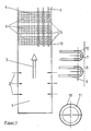
- Example 1 Steam generation plant with coal dust combustion
- heating surfaces 4 In the upper part of the combustion chamber 1 there are 2 heating surfaces 4 above the burners, which are exposed to the hot, ash-laden flue gas flow.
- the melting depth of the surface layers 10 into the base material 11 consisting of 13 Cr Mo 44 is approximately 350 ⁇ m (approximately 6% of the tube wall thickness).
- the surface layers 10 are pore-free and crack-free, have a fine-grained, cellular structure and have pore-free and crack-free connections to the base material 11.
- the surface layers 10 of the heat exchanger tubes for example the lower heat exchanger tubes 5 of the tube bundle 6, were generated with a fixed high-performance CO2 laser ( ⁇ 5 kW) 12 by its laser beam 13 on rotating and transversely moving heat exchanger tubes 5.
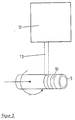
- Example 2 Steam generation plant with fluidized bed combustion
- a fluidized bed 14 consisting of granular material, which is separated from an air chamber by a perforated intermediate floor 15.
- peripheral walls 16 of the combustion chamber 1 are provided with surface-coated heat exchanger tubes 17.
- Immersed in the fluidized bed 14 are immersion heating surfaces 18 in the form of tube sheets, each consisting of a plurality of horizontal heat exchanger tubes 19, the axes of which lie in a vertical plane.
- the heat exchanger tubes 19 of the immersion heating surfaces 18 are also surface-coated.
- a fluidized bed cooler 20 which is connected via an ash duct 21 to the fluidized bed 14 just above the intermediate floor 15, there is a fluidized bed 22 made of ash into which surface-coated heat exchanger tubes 23 in the form of heating surfaces 24 are immersed.
- the surface layers 10 of the heat exchanger tubes 17 and 19 in and in the vicinity of the fluidized bed 14 of the fluidized bed furnace and the heat exchanger tubes 23 in the fluidized bed 22 of the fluidized bed cooler 20 are coatings 10 made of WC particles melted by the laser 12 and applied by plasma spraying in a co-matrix.
- the layer thickness of the coatings is approximately 100 ⁇ m (approximately 2% of the tube wall thickness) and the melting depth of the surface layers 10 is approximately three times the layer thickness: 300 ⁇ m.
- the degree of mixing is 67%.
- the surface layers 10 are free of pores and cracks, have a fine-grained, dendritic structure with only a few WC particles and have non-porous and crack-free connections to the base material 11.
- heating surfaces 4 which are designed in the same way as the coal dust combustion of Example 1.
- the fluidized bed 14 in the combustion chamber 1 and the fluidized bed 22 of the fluidized bed cooler 20 are kept in a fluidized state.
- the heat exchanger tubes 17, 19 and 23 which are particularly exposed to the impact of the particles of the fluidized bed material or the ash are protected from wear by the surface layers 10 produced by laser alloying.
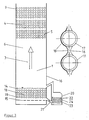
- Example 3 Steam generation plant with partially surface-coated heat exchanger tubes
- the steam generating plant of Example 3 differs from that of Example 2 in that heat exchanger tubes 5, 25, 26 of the three stacked tube bundles 6 of the heating surfaces 4 are partially provided with surface layers 10 produced by laser alloys.
- Two rows of lower heat exchanger tubes 5 of each tube bundle 6 are provided on their lower halves and overlying rows of heat exchanger tubes 25, 26 on their sides with surface layers 10 produced by laser alloys.
- the surface layers 10 of the heat exchanger tubes 25 of the upper rows extend from the sides into the lower half of the heat exchanger tubes 25.
- the surfaces of the heat exchanger tubes 5, 25, 26 of the heating surfaces 4 which are particularly exposed to the flue gas flow are protected against wear by the surface layers 10 produced by laser alloying.
Landscapes
- Engineering & Computer Science (AREA)
- Mechanical Engineering (AREA)
- Chemical & Material Sciences (AREA)
- Metallurgy (AREA)
- Physics & Mathematics (AREA)
- Thermal Sciences (AREA)
- General Engineering & Computer Science (AREA)
- Chemical Kinetics & Catalysis (AREA)
- Materials Engineering (AREA)
- Organic Chemistry (AREA)
- Heat-Exchange Devices With Radiators And Conduit Assemblies (AREA)
- Fluidized-Bed Combustion And Resonant Combustion (AREA)
Applications Claiming Priority (2)
| Application Number | Priority Date | Filing Date | Title |
|---|---|---|---|
| DE3825472 | 1988-07-27 | ||
| DE19883825472 DE3825472A1 (de) | 1988-07-27 | 1988-07-27 | Dampferzeugungsanlage mit waermetauscherrohren |
Publications (1)
| Publication Number | Publication Date |
|---|---|
| EP0352482A1 true EP0352482A1 (de) | 1990-01-31 |
Family
ID=6359647
Family Applications (1)
| Application Number | Title | Priority Date | Filing Date |
|---|---|---|---|
| EP89111545A Withdrawn EP0352482A1 (de) | 1988-07-27 | 1989-06-24 | Dampferzeugungsanlage mit Wärmetauscherrohren |
Country Status (2)
| Country | Link |
|---|---|
| EP (1) | EP0352482A1 (enExample) |
| DE (1) | DE3825472A1 (enExample) |
Cited By (6)
| Publication number | Priority date | Publication date | Assignee | Title |
|---|---|---|---|---|
| EP0684070A1 (en) * | 1994-05-23 | 1995-11-29 | Hemlock Semiconductor Corporation | Fluidized-bed reactor |
| US5910290A (en) * | 1994-10-03 | 1999-06-08 | Foster Wheeler Energia Oy | Arrangement in a wall and a method of coating a wall |
| WO2000049193A1 (de) * | 1999-02-19 | 2000-08-24 | Volkswagen Aktiengesellschaft | Verfahren und vorrichtung zum bearbeiten einer oberfläche eines bauteils |
| WO2008088465A1 (en) | 2007-01-17 | 2008-07-24 | Dow Corning Corporation | Wear resistant materials in the direct process |
| WO2020082322A1 (zh) * | 2018-10-26 | 2020-04-30 | 中国电建集团山东电力建设第一工程有限公司 | 塔式锅炉穿墙管施工方法 |
| CN113503530A (zh) * | 2021-07-19 | 2021-10-15 | 张家港市富昶锅炉制造有限公司 | 一种换热组件及应用其的蒸汽发生器 |
Citations (7)
| Publication number | Priority date | Publication date | Assignee | Title |
|---|---|---|---|---|
| NL69554C (enExample) * | ||||
| FR2307214A1 (fr) * | 1975-04-11 | 1976-11-05 | Eutectic Corp | Revetement de tubes de chaudieres avec une matrice en alliage contenant en dispersion un constituant refractaire |
| FR2409324A3 (fr) * | 1977-11-22 | 1979-06-15 | Skoda Np | Revetement protecteur pour pieces soumises a la chaleur, produit par application sous forme de plasma ou de projection a chaud |
| DE3428696A1 (de) * | 1983-08-05 | 1985-02-21 | Ishikawajima-Harima Jukogyo K.K., Tokio/Tokyo | Vorrichtung zum verhindern des verschleisses von waermeuebertragungsrohren in wirbelbettkesseln |
| DE3412664A1 (de) * | 1984-04-04 | 1985-10-17 | Kraftwerk Union AG, 4330 Mülheim | Rohr fuer ein rohrbuendel in einem waermetauscher |
| US4685427A (en) * | 1986-12-08 | 1987-08-11 | Inco Alloys International, Inc. | Alloy for composite tubing in fluidized-bed coal combustor |
| DD260321A1 (de) * | 1987-05-05 | 1988-09-21 | Bergmann Borsig Veb | Waermeuebertragerrohre fuer tauchheizflaechen |
Family Cites Families (3)
| Publication number | Priority date | Publication date | Assignee | Title |
|---|---|---|---|---|
| JPS583478B2 (ja) * | 1978-03-03 | 1983-01-21 | 株式会社日立製作所 | レ−ザ加熱方法および装置 |
| DE3343783C1 (de) * | 1983-12-03 | 1984-07-05 | M.A.N. Maschinenfabrik Augsburg-Nürnberg AG, 8900 Augsburg | Verfahren zur Herstellung verschleissfester Zylinderlaufflaechen von Brennkraftmaschinen |
| DE3347083A1 (de) * | 1983-12-24 | 1985-07-04 | Vereinigte Kesselwerke AG, 4000 Düsseldorf | Tauchheizflaechen fuer eine wirbelschichtfeuerung |
-
1988
- 1988-07-27 DE DE19883825472 patent/DE3825472A1/de active Granted
-
1989
- 1989-06-24 EP EP89111545A patent/EP0352482A1/de not_active Withdrawn
Patent Citations (7)
| Publication number | Priority date | Publication date | Assignee | Title |
|---|---|---|---|---|
| NL69554C (enExample) * | ||||
| FR2307214A1 (fr) * | 1975-04-11 | 1976-11-05 | Eutectic Corp | Revetement de tubes de chaudieres avec une matrice en alliage contenant en dispersion un constituant refractaire |
| FR2409324A3 (fr) * | 1977-11-22 | 1979-06-15 | Skoda Np | Revetement protecteur pour pieces soumises a la chaleur, produit par application sous forme de plasma ou de projection a chaud |
| DE3428696A1 (de) * | 1983-08-05 | 1985-02-21 | Ishikawajima-Harima Jukogyo K.K., Tokio/Tokyo | Vorrichtung zum verhindern des verschleisses von waermeuebertragungsrohren in wirbelbettkesseln |
| DE3412664A1 (de) * | 1984-04-04 | 1985-10-17 | Kraftwerk Union AG, 4330 Mülheim | Rohr fuer ein rohrbuendel in einem waermetauscher |
| US4685427A (en) * | 1986-12-08 | 1987-08-11 | Inco Alloys International, Inc. | Alloy for composite tubing in fluidized-bed coal combustor |
| DD260321A1 (de) * | 1987-05-05 | 1988-09-21 | Bergmann Borsig Veb | Waermeuebertragerrohre fuer tauchheizflaechen |
Non-Patent Citations (2)
| Title |
|---|
| I.A.Bucklow:Second International Conference on SURFACE ENGINEERING"1987 THE WELDING INSTITUTE, Cambridge,Great Britain Watanabe et al."Surface processing with a high power CO2 laser"Seiten 131-140 * |
| PATENT ABSTRACTS OF JAPAN vol. 9, no. 233 (C-304)(1956) 19 September 85, & JP-A-60 92461 (KOGYO GIJUTSUIN) 24 Mai 85, * |
Cited By (7)
| Publication number | Priority date | Publication date | Assignee | Title |
|---|---|---|---|---|
| EP0684070A1 (en) * | 1994-05-23 | 1995-11-29 | Hemlock Semiconductor Corporation | Fluidized-bed reactor |
| US5910290A (en) * | 1994-10-03 | 1999-06-08 | Foster Wheeler Energia Oy | Arrangement in a wall and a method of coating a wall |
| WO2000049193A1 (de) * | 1999-02-19 | 2000-08-24 | Volkswagen Aktiengesellschaft | Verfahren und vorrichtung zum bearbeiten einer oberfläche eines bauteils |
| WO2008088465A1 (en) | 2007-01-17 | 2008-07-24 | Dow Corning Corporation | Wear resistant materials in the direct process |
| JP2010516990A (ja) * | 2007-01-17 | 2010-05-20 | ダウ・コーニング・コーポレイション | 直接法における耐摩耗性材料 |
| WO2020082322A1 (zh) * | 2018-10-26 | 2020-04-30 | 中国电建集团山东电力建设第一工程有限公司 | 塔式锅炉穿墙管施工方法 |
| CN113503530A (zh) * | 2021-07-19 | 2021-10-15 | 张家港市富昶锅炉制造有限公司 | 一种换热组件及应用其的蒸汽发生器 |
Also Published As
| Publication number | Publication date |
|---|---|
| DE3825472A1 (de) | 1990-02-01 |
| DE3825472C2 (enExample) | 1992-10-01 |
Similar Documents
| Publication | Publication Date | Title |
|---|---|---|
| DE2613588C2 (de) | Verwendung einer Beschichtungsmasse zur Ausbildung einer äußeren Schutzschicht auf Leitungsrohren | |
| DE2925395C2 (de) | Ofendecke für einen elektrothermischen Reduktionsofen | |
| EP0352482A1 (de) | Dampferzeugungsanlage mit Wärmetauscherrohren | |
| DE102005032118A1 (de) | Rohrbündelwärmeübertrager mit verschleißbeständiger Rohrbodenauskleidung | |
| DE2149772C2 (de) | Schweißzusatz werkstoff aus härtbaren Hartstofflegierungen | |
| DE2552637A1 (de) | Plattenkuehler fuer schachtofen, insbesondere hochofen, und verfahren zur dessen ausfuehrung | |
| EP0415038A1 (de) | Rohrwand für Heissreaktionsräume | |
| DE3821896C2 (enExample) | ||
| EP0672197A1 (de) | Verfahren zur herstellung einer schutzschicht auf mit heissen gasen, insbesondere rauchgasen beaufschlagten metallischen wänden | |
| DE68908705T2 (de) | Vorrichtung und verfahren zum diffusionsverchromen von gegenständen. | |
| DE3816348C2 (enExample) | ||
| DE10356679A1 (de) | Verfahren und Vorrichtung zur Beschichtung oder Wärmebehandlung von BLISK-Scheiben für Fluggasturbinen | |
| EP1674815B1 (de) | Wärmetauscher zum Kühlen eines Feststoffpartikel enthaltenden heissen Gases | |
| DE2951640C2 (de) | Kühlplatte für einen Hüttenwerksofen, insbesondere Hochofen, und Verfahren zu ihrer Herstellung | |
| DE2341117C3 (de) | Reaktionskammer zur katalytischen Verbrennung des Kohlenmonoxid-Anteiles von Rauchgasen | |
| EP0687746A1 (de) | Metallischer Bauteil zur Verwendung in einem Metallbad | |
| Koshy | Laser cladding techniques for application to wear and corrosion resistant coatings | |
| JP3032341B2 (ja) | 耐摩耗伝熱管の製造方法 | |
| DE3822874C2 (enExample) | ||
| DE3908277C2 (de) | Erosionsschutz für Wärmetauscher | |
| EP0302235A1 (de) | Pulverförmiger metallhaltiger Werkstoff und Verfahren zum Herstellen von Schutzschichten an Rohren für Vorwärmer und Ekonomiser | |
| EP0846930B1 (de) | Vorrichtung zur gleichmässigen Beaufschlagung einer planen Oberfläche eines Werkstückes mit einem Wärmebehandlungsgas | |
| DE3810454A1 (de) | Kraftanlage zur verbrennung von brennstoff in einem wirbelbett | |
| DE976381C (de) | Verfahren zum Herstellen einer Schutzschicht auf thermisch hoch beanspruchten, zunderfesten Metallteilen | |
| EP0349765B1 (de) | Wirbelschichtfeuerung |
Legal Events
| Date | Code | Title | Description |
|---|---|---|---|
| PUAI | Public reference made under article 153(3) epc to a published international application that has entered the european phase |
Free format text: ORIGINAL CODE: 0009012 |
|
| AK | Designated contracting states |
Kind code of ref document: A1 Designated state(s): DE FR GB SE |
|
| 17P | Request for examination filed |
Effective date: 19900214 |
|
| 17Q | First examination report despatched |
Effective date: 19910516 |
|
| RAP1 | Party data changed (applicant data changed or rights of an application transferred) |
Owner name: DEUTSCHE BABCOCK ENERGIE- UND UMWELTTECHNIK AKTIEN |
|
| STAA | Information on the status of an ep patent application or granted ep patent |
Free format text: STATUS: THE APPLICATION HAS BEEN WITHDRAWN |
|
| 18W | Application withdrawn |
Withdrawal date: 19930428 |