EP0352482A1 - Steam-generating plant with heat exchanger tubes - Google Patents
Steam-generating plant with heat exchanger tubes Download PDFInfo
- Publication number
- EP0352482A1 EP0352482A1 EP89111545A EP89111545A EP0352482A1 EP 0352482 A1 EP0352482 A1 EP 0352482A1 EP 89111545 A EP89111545 A EP 89111545A EP 89111545 A EP89111545 A EP 89111545A EP 0352482 A1 EP0352482 A1 EP 0352482A1
- Authority
- EP
- European Patent Office
- Prior art keywords
- heat exchanger
- surface layers
- laser
- hard
- exchanger tubes
- Prior art date
- Legal status (The legal status is an assumption and is not a legal conclusion. Google has not performed a legal analysis and makes no representation as to the accuracy of the status listed.)
- Withdrawn
Links
Images

Classifications
-
- B—PERFORMING OPERATIONS; TRANSPORTING
- B23—MACHINE TOOLS; METAL-WORKING NOT OTHERWISE PROVIDED FOR
- B23K—SOLDERING OR UNSOLDERING; WELDING; CLADDING OR PLATING BY SOLDERING OR WELDING; CUTTING BY APPLYING HEAT LOCALLY, e.g. FLAME CUTTING; WORKING BY LASER BEAM
- B23K35/00—Rods, electrodes, materials, or media, for use in soldering, welding, or cutting
- B23K35/22—Rods, electrodes, materials, or media, for use in soldering, welding, or cutting characterised by the composition or nature of the material
- B23K35/24—Selection of soldering or welding materials proper
- B23K35/32—Selection of soldering or welding materials proper with the principal constituent melting at more than 1550 degrees C
- B23K35/327—Selection of soldering or welding materials proper with the principal constituent melting at more than 1550 degrees C comprising refractory compounds, e.g. carbides
-
- C—CHEMISTRY; METALLURGY
- C23—COATING METALLIC MATERIAL; COATING MATERIAL WITH METALLIC MATERIAL; CHEMICAL SURFACE TREATMENT; DIFFUSION TREATMENT OF METALLIC MATERIAL; COATING BY VACUUM EVAPORATION, BY SPUTTERING, BY ION IMPLANTATION OR BY CHEMICAL VAPOUR DEPOSITION, IN GENERAL; INHIBITING CORROSION OF METALLIC MATERIAL OR INCRUSTATION IN GENERAL
- C23C—COATING METALLIC MATERIAL; COATING MATERIAL WITH METALLIC MATERIAL; SURFACE TREATMENT OF METALLIC MATERIAL BY DIFFUSION INTO THE SURFACE, BY CHEMICAL CONVERSION OR SUBSTITUTION; COATING BY VACUUM EVAPORATION, BY SPUTTERING, BY ION IMPLANTATION OR BY CHEMICAL VAPOUR DEPOSITION, IN GENERAL
- C23C26/00—Coating not provided for in groups C23C2/00 - C23C24/00
- C23C26/02—Coating not provided for in groups C23C2/00 - C23C24/00 applying molten material to the substrate
-
- F—MECHANICAL ENGINEERING; LIGHTING; HEATING; WEAPONS; BLASTING
- F22—STEAM GENERATION
- F22B—METHODS OF STEAM GENERATION; STEAM BOILERS
- F22B37/00—Component parts or details of steam boilers
- F22B37/02—Component parts or details of steam boilers applicable to more than one kind or type of steam boiler
- F22B37/04—Component parts or details of steam boilers applicable to more than one kind or type of steam boiler and characterised by material, e.g. use of special steel alloy
-
- F—MECHANICAL ENGINEERING; LIGHTING; HEATING; WEAPONS; BLASTING
- F28—HEAT EXCHANGE IN GENERAL
- F28F—DETAILS OF HEAT-EXCHANGE AND HEAT-TRANSFER APPARATUS, OF GENERAL APPLICATION
- F28F19/00—Preventing the formation of deposits or corrosion, e.g. by using filters or scrapers
Definitions
- the invention relates to a steam generating plant according to the preamble of claim 1.
- the thermal spraying of protective layers usually leads to pores in the surface, which serve especially as abrasive quartz sand as new attack surfaces.
- these layers usually have completely different coefficients of expansion than the base material, so that either only very thin and ineffective layers are sprayed on or the layers flake off after a short operating time.
- the object of the invention is to develop a steam generating plant in which the wear of the heat exchanger tubes is reduced without significantly influencing the properties, such as the heat transfer or the heat resistance.
- the special advantages of a surface layer created by laser heat treatment are: - a smooth, non-porous surface without contact points for the abrasive quartz sand, - a homogeneous, fine-grained structure of increased hardness, - a selectable hardening depth, - No significant change in the heat and strength properties with temperature and pressure cycling - no cracking and - a non-porous transition to the base material.
- An advantage of the features of claims 2, 3 and 4 is that the heat exchanger tubes, or parts thereof, which are particularly exposed to erosion by the flue gas flow, are protected against wear on their entire surface or partially by laser-heat-treated surfaces.
- Heat exchanger tubes from heating surfaces in the flue gas flue are particularly exposed to the flow of flue gas, especially the heat exchanger tubes of the tube bundle that have flowed first, in particular of the tube bundle that is flowed to first.
- the heating surfaces in the flue gas flue can be preheaters, evaporators or superheaters.
- claims 2, 3 and 4 are suitable both for coal dust furnaces where the flue gas flow hits the heating surfaces at high speed and low ash loading, as well as for fluidized bed furnaces where the flue gas speed is lower but the ash loading is higher than with coal dust furnaces.
- the particular advantage of the feature of claim 3 is that the wear is reduced by the partially applied laser-heat-treated surface layers without warping occurring.
- An advantage of the features of claims 5 and 6 is that the heat exchanger tubes of the surrounding walls in the area of the fluidized bed, which are particularly exposed to the erosion caused by the fluidized bed and the corrosion caused by the reducing atmosphere in the fluidized bed, and those of the immersion heating surfaces of the fluidized bed, are protected from wear by laser-heat-treated hard surfaces are.
- An advantage of the feature of claim 7 is that the heat exchanger tubes of a fluidized bed cooler, which are exposed to the erosion by hot ash, are protected against wear by laser heat-treated, hard surfaces.
- the feature of claim 8 is particularly suitable for heat exchanger tubes whose wear is moderate.
- a surface layer created by laser melting and self-quenching has a fine-grained structure of increased hardness and increased wear resistance. It is inexpensive and quick to manufacture. Heat exchanger tubes provided with such a surface layer can be cold worked without cracking.
- the feature of claim 9 is particularly for heat exchanger tubes which consist of heat-resistant or heat-resistant steels for boiler construction, in particular of 13 Cr Mo 44, suitable.
- the surface layers With a melting depth of 200 to 1500 ⁇ m, in particular from 300 to 600 ⁇ m, the surface layers are particularly homogeneous, free of pores and cracks and have a fine-grained, cellular structure.
- the wear rates of these surface layers determined on the basis of sliding wear experiments are approximately half that of the untreated base material.
- An advantage of the feature of claim 10 is that the hardness and wear resistance of the surface layers are further increased by the hardening constituents. These surface layers provide even better protection against erosion and corrosion.
- the hardening components are finely distributed in the melted base material. The choice of hardening components is not subject to any restrictions due to the different thermal expansion of hard material and base material.
- the feature of claim 11 is particularly suitable for thinner surface layers. Since the hardening constituents are supplied during laser melting and only one work step is necessary, these surface layers can be produced inexpensively.
- the feature of claim 12 is particularly suitable for thicker surface layers and layer structures with different hardnesses, for example with a hardness that varies on the circumference. These surface layers are also homogeneous because melted metallic, hardening components are partially melted and are particularly finely distributed. A degree of mixing of 30 to 75% leads to surface layers that have great hardness and wear resistance with good resistance to temperature and pressure changes.
- the feature of claim 13 is particularly suitable for heat exchangers made of heat-resistant or heat-resistant steels, in particular for boiler construction, in particular of 13 Cr Mo 44.
- An advantage of the feature of claim 14 is that the surface layers are particularly homogeneous, free of pores and cracks and have a fine-grained, dendritic structure with isolated, smaller toilet particles.
- the wear rates of these hard surface layers are only about 2% of that of the untreated base material.
- the advantage of the feature of claim 15 is a further increase in the hardness and wear resistance of the surface layers.
- Example 1 Steam generation plant with coal dust combustion
- heating surfaces 4 In the upper part of the combustion chamber 1 there are 2 heating surfaces 4 above the burners, which are exposed to the hot, ash-laden flue gas flow.
- the melting depth of the surface layers 10 into the base material 11 consisting of 13 Cr Mo 44 is approximately 350 ⁇ m (approximately 6% of the tube wall thickness).
- the surface layers 10 are pore-free and crack-free, have a fine-grained, cellular structure and have pore-free and crack-free connections to the base material 11.
- the surface layers 10 of the heat exchanger tubes for example the lower heat exchanger tubes 5 of the tube bundle 6, were generated with a fixed high-performance CO2 laser ( ⁇ 5 kW) 12 by its laser beam 13 on rotating and transversely moving heat exchanger tubes 5.
- Example 2 Steam generation plant with fluidized bed combustion
- a fluidized bed 14 consisting of granular material, which is separated from an air chamber by a perforated intermediate floor 15.
- peripheral walls 16 of the combustion chamber 1 are provided with surface-coated heat exchanger tubes 17.
- Immersed in the fluidized bed 14 are immersion heating surfaces 18 in the form of tube sheets, each consisting of a plurality of horizontal heat exchanger tubes 19, the axes of which lie in a vertical plane.
- the heat exchanger tubes 19 of the immersion heating surfaces 18 are also surface-coated.
- a fluidized bed cooler 20 which is connected via an ash duct 21 to the fluidized bed 14 just above the intermediate floor 15, there is a fluidized bed 22 made of ash into which surface-coated heat exchanger tubes 23 in the form of heating surfaces 24 are immersed.
- the surface layers 10 of the heat exchanger tubes 17 and 19 in and in the vicinity of the fluidized bed 14 of the fluidized bed furnace and the heat exchanger tubes 23 in the fluidized bed 22 of the fluidized bed cooler 20 are coatings 10 made of WC particles melted by the laser 12 and applied by plasma spraying in a co-matrix.
- the layer thickness of the coatings is approximately 100 ⁇ m (approximately 2% of the tube wall thickness) and the melting depth of the surface layers 10 is approximately three times the layer thickness: 300 ⁇ m.
- the degree of mixing is 67%.
- the surface layers 10 are free of pores and cracks, have a fine-grained, dendritic structure with only a few WC particles and have non-porous and crack-free connections to the base material 11.
- heating surfaces 4 which are designed in the same way as the coal dust combustion of Example 1.
- the fluidized bed 14 in the combustion chamber 1 and the fluidized bed 22 of the fluidized bed cooler 20 are kept in a fluidized state.
- the heat exchanger tubes 17, 19 and 23 which are particularly exposed to the impact of the particles of the fluidized bed material or the ash are protected from wear by the surface layers 10 produced by laser alloying.
- Example 3 Steam generation plant with partially surface-coated heat exchanger tubes
- the steam generating plant of Example 3 differs from that of Example 2 in that heat exchanger tubes 5, 25, 26 of the three stacked tube bundles 6 of the heating surfaces 4 are partially provided with surface layers 10 produced by laser alloys.
- Two rows of lower heat exchanger tubes 5 of each tube bundle 6 are provided on their lower halves and overlying rows of heat exchanger tubes 25, 26 on their sides with surface layers 10 produced by laser alloys.
- the surface layers 10 of the heat exchanger tubes 25 of the upper rows extend from the sides into the lower half of the heat exchanger tubes 25.
- the surfaces of the heat exchanger tubes 5, 25, 26 of the heating surfaces 4 which are particularly exposed to the flue gas flow are protected against wear by the surface layers 10 produced by laser alloying.
Abstract
Description
Die Erfindung betrifft eine Dampferzeugungsanlage gemäß dem Oberbegriff des Patentanspruchs 1.The invention relates to a steam generating plant according to the preamble of
Ein Problem beim Betreiben einer Dampferzeugungsanlage ist der Verschleiß von Wärmetauscherrohren. Es tritt verstärkt bei Dampferzeugungsanlagen mit Kohlenstaub- und Wirbelschichtfeuerungen wegen des hohen Ascheanteils der Rauchgase auf. Speziell durch den im Rauchgas enthaltenen Quarzsand wird die Erosion der Wärmetauscherrohre von Bündelheizflächen und Umfassungswänden gefördert. Wärmetauscherrohre in oder in der Umgebung einer Wirbelschicht sind ebenfalls einer starken Erosion ausgesetzt.One problem when operating a steam generating plant is the wear of heat exchanger tubes. It occurs increasingly in steam generation plants with coal dust and fluidized bed firing because of the high ash content of the flue gases. Especially the quartz sand contained in the flue gas promotes the erosion of the heat exchanger tubes of bundle heating surfaces and surrounding walls. Heat exchanger tubes in or in the vicinity of a fluidized bed are also subject to severe erosion.
Das besondere Problem dieser Wärmetauscherrohre ist, daß sie durch ständige Temperatur- und Druckwechsel Dehnungen ausgesetzt sind. Aus diesem Grund werden zähe Stähle mit geringem Kohlenstoffanteil eingesetzt.The special problem of these heat exchanger tubes is that they are exposed to expansions due to constant changes in temperature and pressure. For this reason, tough steels with a low carbon content are used.
Zum Schutz solcher Wärmetauscherrohre ist es bekannt, sie durch thermische Spritzverfahren, zum Beispiel durch Plasmaspritzen, mit einer harten Oberfläche zu versehen.To protect such heat exchanger tubes, it is known to provide them with a hard surface by thermal spraying processes, for example by plasma spraying.
Das thermische Aufspritzen von Schutzschichten führt meist zu Poren in der Oberfläche, die besonders dem abrasiven Quarzsand als neue Angriffsflächen dienen.The thermal spraying of protective layers usually leads to pores in the surface, which serve especially as abrasive quartz sand as new attack surfaces.
Darüber hinaus haben diese Schichten meist völlig andere Ausdehnungskoeffizienten als das Grundmaterial, so daß entweder nur sehr dünne und unwirksame Schichten aufgespritzt werden oder die Schichten nach kurzer Betriebszeit abplatzen.In addition, these layers usually have completely different coefficients of expansion than the base material, so that either only very thin and ineffective layers are sprayed on or the layers flake off after a short operating time.
Es ist außerdem bekannt, an besonders erosionsgefährdeten Stellen die Wärmetauscherrohre mit Schutzelementen oder Schutzmassen zu versehen. Derartige Schutzmaßnahmen für die Wärmetauscherrohre von Tauchheizflächen einer Wirbelschichtfeuerung sind in der DE-OS 33 47 083 beschrieben. Bei einem der Ausführungsbeispiele sind an waagerechte Rohre zu beiden Seiten hochkantstehende Leisten angeschweißt; bei einem anderen Ausführungsbeispiel sind die Rohre in erosionsbeständige Stampfmassen eingebettet.It is also known to provide the heat exchanger tubes with protective elements or protective compounds at particularly erosion-prone locations. Such protective measures for the heat exchanger tubes of immersion heating surfaces of a fluidized bed furnace are described in DE-OS 33 47 083. In one of the exemplary embodiments, upright strips are welded to horizontal pipes on both sides; in another embodiment, the tubes are embedded in erosion-resistant ramming compounds.
In speziellen Bereichen des Maschinen- oder Werkzeugbaus ist es bekannt, besonders verschleißfeste Oberflächen durch Laserstrahlwärmebehandlungen, wie Oberflächenhärten oder Oberflächenlegieren, herzustellen. Mit Hilfe von Lasern werden zum Beispiel, wie in der DE-PS 33 43 783 beschrieben, Zylinderlaufflächen bearbeitet oder, wie von J. Watanabe et al. (Preprint: Second International Conference on Surface Engineering, Stratford-upon-Avon, 15 - 18. June 1987) beschrieben, Rohre mit einer harten Oberfläche versehen. Eine Anlage zur Laserstrahlwärmebehandlung ist zum Beispiel in der DE-PS 29 08 195 beschrieben.In special areas of machine or tool construction, it is known to produce particularly wear-resistant surfaces by means of laser beam heat treatments, such as surface hardening or surface alloying. With the help of lasers, for example, as described in DE-PS 33 43 783, cylinder running surfaces are machined or, as described by J. Watanabe et al. (Preprint: Second International Conference on Surface Engineering, Stratford-upon-Avon, June 15-18, 1987) described, pipes with a hard surface. A system for laser beam heat treatment is described for example in DE-PS 29 08 195.
Aufgabe der Erfindung ist, eine Dampferzeugungsanlage zu entwickeln, in der der Verschleiß der Wärmetauscherrohre ohne wesentliche Beeinflussung der Eigenschaften, wie die Wärmeübertragung oder die Warmfestigkeit, reduziert ist.The object of the invention is to develop a steam generating plant in which the wear of the heat exchanger tubes is reduced without significantly influencing the properties, such as the heat transfer or the heat resistance.
Die Aufgabe wird erfindungsgemäß durch die kennzeichnenden Merkmale des Patentanspruchs 1 gelöst.The object is achieved by the characterizing features of
Durch gezielten Oberflächenschutz in Form von laserwärmebehandelten, harten Oberflächen der der Erosion besonders ausgesetzten Wärmetauscherrohre, wird ihr Verschleiß erheblich reduziert.Targeted surface protection in the form of laser heat-treated, hard surfaces of the heat exchanger tubes, which are particularly exposed to erosion, significantly reduces their wear.
Der Aufwand durch Schutzelemente oder die auf die Wärmeübertragung nachteilige Wirkung einer Stampfmasse entfällt. Außerdem bilden diese Oberflächenschichten einen guten Korrosionsschutz, der besonders bei reduzierender Atmosphäre von Vorteil ist.The expense of protective elements or the disadvantageous effect of a ramming mass on heat transfer is eliminated. In addition, these surface layers form good corrosion protection, which is particularly advantageous in a reducing atmosphere.
Die besonderen Vorteile einer durch Laserwärmebehandlung erzeugten Oberflächenschicht sind:
- eine glatte, porenfreie Oberfläche ohne Angriffstellen für den abrasiven Quarzsand,
- ein homogenes, feinkörniges Gefüge erhöhter Härte,
- eine wählbare Einhärttiefe,
- keine wesentliche Veränderung der Wärme- und Festigkeitseigenschaften bei Temperatur- und Druckwechselbeanspruchung
- keine Rißbildung und
- ein porenfreier Übergang zum Grundmaterial.The special advantages of a surface layer created by laser heat treatment are:
- a smooth, non-porous surface without contact points for the abrasive quartz sand,
- a homogeneous, fine-grained structure of increased hardness,
- a selectable hardening depth,
- No significant change in the heat and strength properties with temperature and pressure cycling
- no cracking and
- a non-porous transition to the base material.
Vorteil der Merkmale der Ansprüche 2, 3 und 4 ist, daß die der Erosion durch die Rauchgasströmung besonders ausgesetzten Wärmetauscherrohre oder Teile davon auf ihrer gesamten Oberfläche oder partiell durch laserwärmebehandelte Oberflächen vor Verschleiß geschützt sind. Der Rauchgasströmung besonders ausgesetzt sind Wärmetauscherrohre von Heizflächen im Rauchgaszug, speziell die zuerst angeströmten Wärmetauscherrohre der Rohrbündel, insbesondere des zuerst angeströmten Rohrbündels. Bei den Heizflächen im Rauchgaszug kann es sich um Vorwärmer-, Verdampfer-oder Überhitzerheizflächen handeln. Die Merkmale der Ansprüche 2, 3 und 4 sind sowohl für Kohlenstaubfeuerungen, bei denen die Rauchgasströmung mit hoher Geschwindigkeit und niedriger Aschebeladung auf die Heizflächen trifft, als auch für Wirbelschichtfeuerungen, bei denen die Rauchgasgeschwindigkeit niedriger, die Aschebeladung dagegen höher als bei den Kohlenstaubfeuerungen ist, geeignet. Der besondere Vorteil des Merkmals des Anspruchs 3 ist, daß durch die partiell angebrachten laserwärmebehandelten Oberflächenschichten der Verschleiß verringert wird, ohne daß Verzug auftritt.An advantage of the features of
Vorteil der Merkmale der Ansprüche 5 und 6 ist, daß die der Erosion durch die Wirbelschicht und der Korrosion durch die reduzierende Atmosphäre in der Wirbelschicht besonders ausgesetzten Wärmetauscherrohre der Umfassungswände im Bereich der Wirbelschicht und die der Tauchheizflächen der Wirbelschicht durch laserwärmebehandelte, harte Oberflächen vor Verschleiß geschützt sind.An advantage of the features of
Vorteil des Merkmals des Anspruchs 7 ist, daß die der Erosion durch heiße Asche ausgesetzten Wärmetauscherrohre eines Wirbelbettkühlers durch laserwärmebehandelte, harte Oberflächen vor Verschleiß geschützt sind.An advantage of the feature of
Das Merkmal des Anspruchs 8 ist besonders für Wärmetauscherrohre, deren Verschleiß mäßig ist, geeignet. Eine durch Laseraufschmelzen und Selbstabschreckung entstandene Oberflächenschicht verfügt über ein feinkörniges Gefüge erhöhter Härte und erhöhter Verschleißfestigkeit. Sie ist kostengünstig und schnell zu fertigen. Mit einer derartigen Oberflächenschicht versehene Wärmetauscherrohre sind ohne Rißbildung kaltverformbar.The feature of
Das Merkmal des Anspruchs 9 ist besonders für Wärmetauscherrohre, die aus warmfesten oder hochwarmfesten Stählen für den Kesselbau, insbesondere aus 13 Cr Mo 44, bestehen, geeignet. Bei einer Einschmelztiefe 200 bis 1500 µm, insbesondere von 300 bis 600 µm sind die Oberflächenschichten besonders homogen, poren- und rißfrei und weisen ein feinkörniges, zellulares Gefüge auf. Die anhand von Gleitverschleißexperimenten ermittelten Verschleißraten dieser Oberflächenschichten sind etwa halb so groß wie die des unbehandelten Grundmaterials.The feature of
Vorteil des Merkmals des Anspruchs 10 ist, daß die Härte und die Verschleißfestigkeit der Oberflächenschichten durch die härtenden Bestandteile weiter erhöht sind. Diese Oberflächenschichten bilden einen noch besseren Erosions- und Korrosionsschutz. Die härtenden Bestandteile werden beim Laserlegieren fein in dem aufgeschmolzenen Grundmaterial verteilt. Die Wahl der härtenden Bestandteile unterliegt keiner Beschränkung durch unterschiedliche Wärmedehnung von Hartwerkstoff und Grundmaterial.An advantage of the feature of
Das Merkmal des Anspruchs 11 ist besonders für dünnere Oberflächenschichten geeignet. Da die härtenden Bestandteile während des Laseraufschmelzens zugeführt werden und dadurch nur ein Arbeitsgang notwendig ist, sind diese Oberflächenschichten kostengünstig herzustellen.The feature of
Das Merkmal des Anspruchs 12 ist besonders für dickere Oberflächenschichten und Schichtaufbauten mit unterschiedlichen Härten, zum Beispiel mit am Umfang veränderlicher Härte, geeignet. Diese Oberflächenschichten sind außerdem homogen, weil eingeschmolzene metallische, härtende Bestandteile teilweise aufgeschmolzen und besonders fein verteilt sind. Ein Aufmischungsgrad von 30 bis 75 % führt zu Oberflächenschichten, die große Härte und Verschleißfestigkeit bei guter Temperatur- und Druckwechselbeanspruchbarkeit aufweisen. Der Aufmischungsgrad A ist als Differenz zwischen Gesamtdicke d der Oberflächenschicht nach dem Aufschmelzen und der Dicke dh der Hartwerkstoffschicht bezogen auf die Gesamtdicke d definiert:
A = (d - dh)/d.The feature of
A = (d - d h ) / d.
Das Merkmal des Anspruchs 13 ist besonders für Wärmetauscher aus warmfesten oder hochwarmfesten Stählen, insbesondere für den Kesselbau, insbesondere aus 13 Cr Mo 44, geeignet.The feature of
Vorteil des Merkmals des Anspruchs 14 ist, daß die Oberflächenschichten besonders homogen, poren- und rißfrei sind und ein feinkörniges, dendritisches Gefüge mit vereinzelten, kleineren WC-Teilchen aufweisen. Die Verschleißraten dieser harten Oberflächenschichten betragen nur etwa 2 % der des unbehandelten Grundmaterials.An advantage of the feature of
Vorteil des Merkmals des Anspruchs 15 ist eine weitere Erhöhung der Härte und der Verschleißfestigkeit der Oberflächenschichten.The advantage of the feature of claim 15 is a further increase in the hardness and wear resistance of the surface layers.
Die Zeichnung dient zur Erläuterung der Erfindung anhand schematisch dargestellter Ausführungsbeispiele.
Figur 1 zeigt einen Schnitt durch eine Kohlenstaubfeuerung (Beispiel 1) mit einem vergrößerten Ausschnitt aus den Heizflächen.- In Figur 2 ist eine Anlage zum Laserbehandeln von Wärmetauscherrohren skizziert.
Figur 3 zeigt einen Schnitt durch eine Wirbelschichtfeuerung (Beispiel 2) mit einem vergrößerten Ausschnitt aus der Umfassungswand und einem Wirbelbettkühler.Figur 4 zeigt Wärmetauscherrohre von Heizflächen einer Kohlenstaubfeuerung (Beispiel 3), die partiell Oberflächenschichten aufweisen.
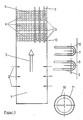
- Figure 1 shows a section through a coal dust combustion (Example 1) with an enlarged section of the heating surfaces.
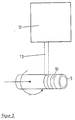
- A system for laser treatment of heat exchanger tubes is outlined in FIG.
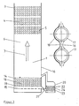
- FIG. 3 shows a section through a fluidized bed furnace (example 2) with an enlarged section of the surrounding wall and a fluidized bed cooler.
- FIG. 4 shows heat exchanger tubes from heating surfaces of a coal dust furnace (example 3), which partially have surface layers.
Im Feuerraum 1 einer Dampferzeugungsanlage mit Kohlenstaubfeuerung sind drei Brennerebenen mit je vier Brennern 2, von denen jeweils zwei pro Brennerebene in Figur 1 durch waagerechte Pfeile symbolisiert sind, übereinander angeordnet. Die Richtung der Rauchgasströmung ist durch einen senkrechten Pfeil 3 angegeben.In the
Im oberen Teil des Feuerraumes 1 befinden sich oberhalb der Brenner 2 Heizflächen 4, die der heißen, aschebeladenen Rauchgasströmung ausgesetzt sind. Untere Wärmetauscherrohre 5 von drei übereinanderliegenden Rohrbündeln 6, Rohrbögen 7 im Bereich der Feuerraumwand 8, sowie Teile der Tragrohre 9 der Heizflächen 4 sind mit durch Laserumschmelzen erzeugten, harten Oberflächenschichten 10 versehen.In the upper part of the
Die Einschmelztiefe der Oberflächenschichten 10 in das aus 13 Cr Mo 44 bestehende Grundmaterial 11 beträgt etwa 350 µm (etwa 6 % der Rohrwanddicke). Die Oberflächenschichten 10 sind poren- und rißfrei, haben ein feinkörniges, zellulares Gefüge und weisen poren- und rißfreie Verbindungen mit dem Grundmaterial 11 auf.The melting depth of the surface layers 10 into the
Die Oberflächenschichten 10 der Wärmetauscherrohre, zum Beispiel der unteren Wärmetauscherrohre 5 der Rohrbündel 6, sind mit einem feststehenden Hochleistungs-CO₂-Laser (≧ 5 kW) 12 durch dessen Laserstrahl 13 auf rotierenden und transversal bewegten Wärmetauscherrohren 5 erzeugt worden.The surface layers 10 of the heat exchanger tubes, for example the lower
Im Betrieb strömen Rauchgase in Richtung des Pfeils 3 von unten nach oben durch den Feuerraum 1. Mitgerissene Ascheteilchen treffen auf die Heizflächen 4. Die der Rauchgasströmung besonders ausgesetzten unteren Wärmetauscherrohre 5 der Rohrbündel 6, insbesondere die des unteren Rohrbündels 6, an denen außerdem aufgewirbelte, schwere Teilchen abprallen, sowie Rohrbögen 7 und Teile der Tragrohre 9 sind durch die durch Laserumschmelzen erzeugten Oberflächenschichten 10 vor Verschleiß geschützt.In operation, flue gases flow in the direction of
In der unteren Hälfte eines Feuerraumes 1 einer Dampferzeugungsanlage mit Wirbelschichtfeuerung befindet sich eine aus körnigem Material bestehende Wirbelschicht 14, die nach unten durch einen perforierten Zwischenboden 15 von einer Luftkammer abgetrennt ist.In the lower half of a
Im Bereich der Wirbelschicht 14 sind Umfassungswände 16 des Feuerraums 1 mit oberflächenbeschichteten Wärmetauscherrohren 17 versehen.In the area of the
Eingetaucht in die Wirbelschicht 14 sind Tauchheizflächen 18 in Gestalt von Rohrtafeln, die jeweils aus mehreren waagerechten Wärmetauscherrohren 19, deren Achsen in einer senkrecht stehenden Ebene liegen, bestehen. Die Wärmetauscherrohre 19 der Tauchheizflächen 18 sind ebenfalls oberflächenbeschichtet.Immersed in the
In einem Wirbelbettkühler 20, der über einen Aschekanal 21 an die Wirbelschicht 14 kurz oberhalb des Zwischenbodens 15 angeschlossen ist, befindet sich ein aus Asche bestehendes Wirbelbett 22, in das oberflächenbeschichtete Wärmetauscherrohre 23 in Form von Heizflächen 24 eintauchen.In a fluidized bed cooler 20, which is connected via an ash duct 21 to the
Die Oberflächenschichten 10 der Wärmetauscherrohre 17 und 19 in und in der Umgebung der Wirbelschicht 14 der Wirbelschichtfeuerung und die Wärmetauscherrohre 23 im Wirbelbett 22 des Wirbelbettkühlers 20 sind durch den Laser 12 eingeschmolzene, durch Plasmaspritzen aufgebrachte Beschichtungen 10 aus WC-Teilchen in einer Co-Matrix.The surface layers 10 of the
Die Schichtdicke der Beschichtungen beträgt etwa 100 µm (etwa 2 % der Rohrwanddicke) und die Einschmelztiefe der Oberflächenschichten 10 etwa das Dreifache der Schichtdicke: 300 µm. Der Aufmischungsgrad beträgt dabei 67 %. Die Oberflächenschichten 10 sind poren- und rißfrei, haben ein feinkörniges, dendritisches Gefüge mit nur vereinzelten WC-Teilchen und weisen poren- und rißfreie Verbindungen mit dem Grundmaterial 11 auf.The layer thickness of the coatings is approximately 100 μm (approximately 2% of the tube wall thickness) and the melting depth of the surface layers 10 is approximately three times the layer thickness: 300 μm. The degree of mixing is 67%. The surface layers 10 are free of pores and cracks, have a fine-grained, dendritic structure with only a few WC particles and have non-porous and crack-free connections to the
Im oberen Teil des Feuerraumes 1 befinden sich Heizflächen 4, die ebenso wie die der Kohlenstaubfeuerung des Beispiels 1 ausgebildet sind.In the upper part of the
Im Betrieb werden die Wirbelschicht 14 im Feuerraum 1 und das Wirbelbett 22 des Wirbelbettkühlers 20 in fluidisiertem Zustand gehalten. Die dem Aufprall der Teilchen des Wirbelschichtmaterials bzw. der Asche besonders ausgesetzten Wärmetauscherrohre 17, 19 und 23 sind durch die durch Laserlegieren erzeugten Oberflächenschichten 10 vor Verschleiß geschützt.In operation, the
Die Dampferzeugungsanlage des Beispiels 3 unterscheidet sich von der des Beispiels 2 darin, daß Wärmetauscherrohre 5, 25, 26 der drei übereinanderliegenden Rohrbündel 6 der Heizflächen 4 partiell mit durch Laserlegieren hergestellten Oberflächenschichten 10 versehen sind.The steam generating plant of Example 3 differs from that of Example 2 in that
Zwei Reihen unterer Wärmetauscherrohre 5 eines jeden Rohrbündels 6 sind auf ihren unteren Hälften und darüberliegende Reihen von Wärmetauscherrohren 25, 26 an ihren Seiten mit durch Laserlegieren hergestellten Oberflächenschichten 10 versehen. Die Oberflächenschichten 10 der Wärmetauscherrohre 25 der oberen Reihen erstrecken sich von den Seiten bis in die untere Hälfte der Wärmetauscherrohre 25.Two rows of lower
Dies gilt nicht für die Wärmetauscherrohre 26 der oberen Reihe des oberen Rohrbündels 6; die Oberflächenschichten 10 dieser Wärmetauscherrohre 26 erstrecken sich von den Seiten bis in die obere Hälfte der Wärmetauscherrohre 26. Die partiell angebrachten Oberflächenschichten 10 der Wärmetauscherrohre 5, 25, 26 entsprechen den im Beispiel 2 beschriebenen Oberflächenschichten 10 der Wärmetauscherrohre 19 in der Wirbelschicht 14.This does not apply to the
Im Betrieb sind die der Rauchgasströmung besonders ausgesetzten Oberflächen der Wärmetauscherrohre 5, 25, 26 der Heizflächen 4 durch die durch Laserlegieren hergestellten Oberflächenschichten 10 vor Verschleiß geschützt.During operation, the surfaces of the
Claims (15)
- die Wärmetauscherrohre (5, 25, 26) der Heizflächen (4) im Rauchgaszug partiell mit laserwärmebehandelten, harten Oberflächenschichten (10) versehen sind, insbesondere, daß
- stromaufwärts angeordnete Wärmetauscherrohre (5) der Rohrbündel (6) die Oberflächenschichten (10) auf ihren Anströmseiten
- und stromabwärts angeordnete Wärmetauscherrohre (25, 26) der Rohrbündel (6) die Oberflächenschichten (10) an ihren Seiten aufweisen.3. Steam generating plant according to claim 1 or 2, characterized in that
- The heat exchanger tubes (5, 25, 26) of the heating surfaces (4) in the flue gas flue are partially provided with laser-heat-treated, hard surface layers (10), in particular that
- Upstream heat exchanger tubes (5) of the tube bundle (6), the surface layers (10) on their upstream sides
- And downstream heat exchanger tubes (25, 26) of the tube bundle (6) have the surface layers (10) on their sides.
Applications Claiming Priority (2)
| Application Number | Priority Date | Filing Date | Title |
|---|---|---|---|
| DE3825472 | 1988-07-27 | ||
| DE19883825472 DE3825472A1 (en) | 1988-07-27 | 1988-07-27 | STEAM GENERATING SYSTEM WITH HEAT EXCHANGER TUBES |
Publications (1)
| Publication Number | Publication Date |
|---|---|
| EP0352482A1 true EP0352482A1 (en) | 1990-01-31 |
Family
ID=6359647
Family Applications (1)
| Application Number | Title | Priority Date | Filing Date |
|---|---|---|---|
| EP89111545A Withdrawn EP0352482A1 (en) | 1988-07-27 | 1989-06-24 | Steam-generating plant with heat exchanger tubes |
Country Status (2)
| Country | Link |
|---|---|
| EP (1) | EP0352482A1 (en) |
| DE (1) | DE3825472A1 (en) |
Cited By (5)
| Publication number | Priority date | Publication date | Assignee | Title |
|---|---|---|---|---|
| EP0684070A1 (en) * | 1994-05-23 | 1995-11-29 | Hemlock Semiconductor Corporation | Fluidized-bed reactor |
| US5910290A (en) * | 1994-10-03 | 1999-06-08 | Foster Wheeler Energia Oy | Arrangement in a wall and a method of coating a wall |
| WO2000049193A1 (en) * | 1999-02-19 | 2000-08-24 | Volkswagen Aktiengesellschaft | Method and device for treating a component surface |
| WO2008088465A1 (en) | 2007-01-17 | 2008-07-24 | Dow Corning Corporation | Wear resistant materials in the direct process |
| WO2020082322A1 (en) * | 2018-10-26 | 2020-04-30 | 中国电建集团山东电力建设第一工程有限公司 | Construction method for in-wall pipe in tower boiler |
Citations (7)
| Publication number | Priority date | Publication date | Assignee | Title |
|---|---|---|---|---|
| NL69554C (en) * | ||||
| FR2307214A1 (en) * | 1975-04-11 | 1976-11-05 | Eutectic Corp | COATING OF BOILER TUBES WITH AN ALLOY MATRIX CONTAINING A REFRACTORY CONSTITUENT IN DISPERSION |
| FR2409324A3 (en) * | 1977-11-22 | 1979-06-15 | Skoda Np | PROTECTIVE COATING FOR PARTS SUBJECTED TO HEAT, PRODUCED BY APPLICATION IN THE FORM OF PLASMA OR HOT SPRAY |
| DE3428696A1 (en) * | 1983-08-05 | 1985-02-21 | Ishikawajima-Harima Jukogyo K.K., Tokio/Tokyo | DEVICE FOR PREVENTING WEAR OF HEAT TRANSFER TUBES IN FLUID BED BOILERS |
| DE3412664A1 (en) * | 1984-04-04 | 1985-10-17 | Kraftwerk Union AG, 4330 Mülheim | Tube for a tube bundle in a heat exchanger |
| US4685427A (en) * | 1986-12-08 | 1987-08-11 | Inco Alloys International, Inc. | Alloy for composite tubing in fluidized-bed coal combustor |
| DD260321A1 (en) * | 1987-05-05 | 1988-09-21 | Bergmann Borsig Veb | HEAT TRANSFER PIPES FOR DIVING HEATING |
Family Cites Families (3)
| Publication number | Priority date | Publication date | Assignee | Title |
|---|---|---|---|---|
| JPS583478B2 (en) * | 1978-03-03 | 1983-01-21 | 株式会社日立製作所 | Laser heating method and device |
| DE3343783C1 (en) * | 1983-12-03 | 1984-07-05 | M.A.N. Maschinenfabrik Augsburg-Nürnberg AG, 8900 Augsburg | Process for the production of wear-resistant cylinder running surfaces of internal combustion engines |
| DE3347083A1 (en) * | 1983-12-24 | 1985-07-04 | Vereinigte Kesselwerke AG, 4000 Düsseldorf | Immersion heating surfaces for a fluidised-bed furnace |
-
1988
- 1988-07-27 DE DE19883825472 patent/DE3825472A1/en active Granted
-
1989
- 1989-06-24 EP EP89111545A patent/EP0352482A1/en not_active Withdrawn
Patent Citations (7)
| Publication number | Priority date | Publication date | Assignee | Title |
|---|---|---|---|---|
| NL69554C (en) * | ||||
| FR2307214A1 (en) * | 1975-04-11 | 1976-11-05 | Eutectic Corp | COATING OF BOILER TUBES WITH AN ALLOY MATRIX CONTAINING A REFRACTORY CONSTITUENT IN DISPERSION |
| FR2409324A3 (en) * | 1977-11-22 | 1979-06-15 | Skoda Np | PROTECTIVE COATING FOR PARTS SUBJECTED TO HEAT, PRODUCED BY APPLICATION IN THE FORM OF PLASMA OR HOT SPRAY |
| DE3428696A1 (en) * | 1983-08-05 | 1985-02-21 | Ishikawajima-Harima Jukogyo K.K., Tokio/Tokyo | DEVICE FOR PREVENTING WEAR OF HEAT TRANSFER TUBES IN FLUID BED BOILERS |
| DE3412664A1 (en) * | 1984-04-04 | 1985-10-17 | Kraftwerk Union AG, 4330 Mülheim | Tube for a tube bundle in a heat exchanger |
| US4685427A (en) * | 1986-12-08 | 1987-08-11 | Inco Alloys International, Inc. | Alloy for composite tubing in fluidized-bed coal combustor |
| DD260321A1 (en) * | 1987-05-05 | 1988-09-21 | Bergmann Borsig Veb | HEAT TRANSFER PIPES FOR DIVING HEATING |
Non-Patent Citations (2)
| Title |
|---|
| I.A.Bucklow:Second International Conference on SURFACE ENGINEERING"1987 THE WELDING INSTITUTE, Cambridge,Great Britain Watanabe et al."Surface processing with a high power CO2 laser"Seiten 131-140 * |
| PATENT ABSTRACTS OF JAPAN vol. 9, no. 233 (C-304)(1956) 19 September 85, & JP-A-60 92461 (KOGYO GIJUTSUIN) 24 Mai 85, * |
Cited By (6)
| Publication number | Priority date | Publication date | Assignee | Title |
|---|---|---|---|---|
| EP0684070A1 (en) * | 1994-05-23 | 1995-11-29 | Hemlock Semiconductor Corporation | Fluidized-bed reactor |
| US5910290A (en) * | 1994-10-03 | 1999-06-08 | Foster Wheeler Energia Oy | Arrangement in a wall and a method of coating a wall |
| WO2000049193A1 (en) * | 1999-02-19 | 2000-08-24 | Volkswagen Aktiengesellschaft | Method and device for treating a component surface |
| WO2008088465A1 (en) | 2007-01-17 | 2008-07-24 | Dow Corning Corporation | Wear resistant materials in the direct process |
| JP2010516990A (en) * | 2007-01-17 | 2010-05-20 | ダウ・コーニング・コーポレイション | Wear resistant materials in the direct process |
| WO2020082322A1 (en) * | 2018-10-26 | 2020-04-30 | 中国电建集团山东电力建设第一工程有限公司 | Construction method for in-wall pipe in tower boiler |
Also Published As
| Publication number | Publication date |
|---|---|
| DE3825472A1 (en) | 1990-02-01 |
| DE3825472C2 (en) | 1992-10-01 |
Similar Documents
| Publication | Publication Date | Title |
|---|---|---|
| DE2613588C2 (en) | Use of a coating compound to form an external protective layer on conduits | |
| DE2925395C2 (en) | Furnace ceiling for an electrothermal reduction furnace | |
| WO2007006446A1 (en) | Shell-and-tube heat exchanger comprising a wear-resistant tube plate lining | |
| EP0352482A1 (en) | Steam-generating plant with heat exchanger tubes | |
| DE2149772C2 (en) | Welding filler material made from hardenable hard alloys | |
| DE2552637A1 (en) | PLATE COOLERS FOR SHAFT FURNACES, IN PARTICULAR Blast furnaces, AND METHOD OF EXECUTING THESE | |
| EP0415038B1 (en) | Tubewall for a heatreactionroom | |
| DE3541887A1 (en) | HEAT EXCHANGER FOR COOLING SOLIDS CONTAINING GASES | |
| EP0309657B1 (en) | Pulverulent metal-containing material and process for the production of a protective layer | |
| EP0672197B1 (en) | Process for producing a protective coating on metal walls subject to attack by hot gases, especially flue gases | |
| EP1674815B1 (en) | Heat exchanger for cooling a particle laden hot gas | |
| DE3821896C2 (en) | ||
| DE3816348C2 (en) | ||
| DE2341117C3 (en) | Reaction chamber for the catalytic combustion of the carbon monoxide content of flue gases | |
| EP0687746A1 (en) | Metallic constructional element to be used in a metallic bath | |
| DE19534823C2 (en) | Shell and tube heat exchangers | |
| DE2951640C2 (en) | Cooling plate for a metallurgical furnace, in particular a blast furnace, and a method for producing it | |
| JP3032341B2 (en) | Manufacturing method of wear-resistant heat transfer tube | |
| Koshy | Laser cladding techniques for application to wear and corrosion resistant coatings | |
| DE3908277C2 (en) | Protection against erosion for heat exchangers | |
| DE102018203019A1 (en) | Blaslanzenkopf with edge wear protection of the nozzle outlet openings | |
| DE3810454A1 (en) | FUEL SYSTEM FOR THE COMBUSTION OF FUEL IN A FLUID BED | |
| US20010037877A1 (en) | Device and method for cooling fume intakes | |
| DE976381C (en) | Process for producing a protective layer on thermally highly stressed, scale-resistant metal parts | |
| EP0349765B1 (en) | Fluidised-bed combustion |
Legal Events
| Date | Code | Title | Description |
|---|---|---|---|
| PUAI | Public reference made under article 153(3) epc to a published international application that has entered the european phase |
Free format text: ORIGINAL CODE: 0009012 |
|
| AK | Designated contracting states |
Kind code of ref document: A1 Designated state(s): DE FR GB SE |
|
| 17P | Request for examination filed |
Effective date: 19900214 |
|
| 17Q | First examination report despatched |
Effective date: 19910516 |
|
| RAP1 | Party data changed (applicant data changed or rights of an application transferred) |
Owner name: DEUTSCHE BABCOCK ENERGIE- UND UMWELTTECHNIK AKTIEN |
|
| STAA | Information on the status of an ep patent application or granted ep patent |
Free format text: STATUS: THE APPLICATION HAS BEEN WITHDRAWN |
|
| 18W | Application withdrawn |
Withdrawal date: 19930428 |