EP0350195A2 - Procédé et appareil pour l'obtention d'images - Google Patents
Procédé et appareil pour l'obtention d'images Download PDFInfo
- Publication number
- EP0350195A2 EP0350195A2 EP89306530A EP89306530A EP0350195A2 EP 0350195 A2 EP0350195 A2 EP 0350195A2 EP 89306530 A EP89306530 A EP 89306530A EP 89306530 A EP89306530 A EP 89306530A EP 0350195 A2 EP0350195 A2 EP 0350195A2
- Authority
- EP
- European Patent Office
- Prior art keywords
- image
- cylinder
- exposure
- forming material
- protective film
- Prior art date
- Legal status (The legal status is an assumption and is not a legal conclusion. Google has not performed a legal analysis and makes no representation as to the accuracy of the status listed.)
- Withdrawn
Links
Images


Classifications
-
- B—PERFORMING OPERATIONS; TRANSPORTING
- B41—PRINTING; LINING MACHINES; TYPEWRITERS; STAMPS
- B41J—TYPEWRITERS; SELECTIVE PRINTING MECHANISMS, i.e. MECHANISMS PRINTING OTHERWISE THAN FROM A FORME; CORRECTION OF TYPOGRAPHICAL ERRORS
- B41J13/00—Devices or arrangements of selective printing mechanisms, e.g. ink-jet printers or thermal printers, specially adapted for supporting or handling copy material in short lengths, e.g. sheets
- B41J13/10—Sheet holders, retainers, movable guides, or stationary guides
- B41J13/22—Clamps or grippers
- B41J13/223—Clamps or grippers on rotatable drums
- B41J13/226—Clamps or grippers on rotatable drums using suction
-
- G—PHYSICS
- G03—PHOTOGRAPHY; CINEMATOGRAPHY; ANALOGOUS TECHNIQUES USING WAVES OTHER THAN OPTICAL WAVES; ELECTROGRAPHY; HOLOGRAPHY
- G03F—PHOTOMECHANICAL PRODUCTION OF TEXTURED OR PATTERNED SURFACES, e.g. FOR PRINTING, FOR PROCESSING OF SEMICONDUCTOR DEVICES; MATERIALS THEREFOR; ORIGINALS THEREFOR; APPARATUS SPECIALLY ADAPTED THEREFOR
- G03F3/00—Colour separation; Correction of tonal value
- G03F3/10—Checking the colour or tonal value of separation negatives or positives
- G03F3/102—Lamination or delamination method or apparatus for colour proofing systems
-
- G—PHYSICS
- G03—PHOTOGRAPHY; CINEMATOGRAPHY; ANALOGOUS TECHNIQUES USING WAVES OTHER THAN OPTICAL WAVES; ELECTROGRAPHY; HOLOGRAPHY
- G03F—PHOTOMECHANICAL PRODUCTION OF TEXTURED OR PATTERNED SURFACES, e.g. FOR PRINTING, FOR PROCESSING OF SEMICONDUCTOR DEVICES; MATERIALS THEREFOR; ORIGINALS THEREFOR; APPARATUS SPECIALLY ADAPTED THEREFOR
- G03F7/00—Photomechanical, e.g. photolithographic, production of textured or patterned surfaces, e.g. printing surfaces; Materials therefor, e.g. comprising photoresists; Apparatus specially adapted therefor
- G03F7/26—Processing photosensitive materials; Apparatus therefor
- G03F7/34—Imagewise removal by selective transfer, e.g. peeling away
- G03F7/343—Lamination or delamination methods or apparatus for photolitographic photosensitive material
Definitions
- This invention relates to an apparatus and method of forming an image of a single color or overlapped multi-colors by using a difference of adhesion between an exposed portion and a non-exposed portion in a photosensitive layer, and more specifically, it relates to an apparatus and method of forming an image in which a transfer matter very similar to printed matter can be obtained as a prepress proof, etc., for color proofing.
- prepress proofs have been used as means to check the finish, color tone, etc., of final printed matter before printing.
- Prepress proofs are obtained by an overlay method or by a surprint method, and selection among these methods depends on purpose.
- each of the base films is provided with a photosensitive layer for a separated color of an image and subjected irradiation with active beam and development to form an image. Then, these base films are overlaid on one another with registering images of separated colors by the eyes, etc.
- the disadvantage of this method is that an obtained image is affected by lights reflected from overlaid films and differs from the texture of actual printed matter to a great extent.
- the surprint method is disclosed, e.g., in U. S. patents 3,060,023, 3,060,024, 3,060,025 and 3,060,026, in which a plurality of images formed on the photosensitive layers according to images of separated colors are transferred to a single image receptor one after another to form a prepress proof.
- Each of the photosensitive layers may be colored with a color equivalent to the separated color of an image, or a transferred image may be colored with corresponding powder color toners.
- U.S. Patents 3,060,023 and 3,060,026 disclose a transfer method in which a photosensitive layer and an image receptor are brought into flat contact under pressure and are heated, and then these two members are separated. Further, these U.S. Patents also disclose a method in which a photosensitive layer and an image receptor are heated between rollers to transfer an image.
- the problem of the methods of bringing a photosensitive layer and an image receptor into contact and then separating them is that they fail in stable image reproduction if the operational conditions such as separation speed, direction, etc., are not constant. That is, it is problems of these methods that a transferred image shows nonuniformity in reflection density, very small periodic patterns and very small directionally repetitive patterns; markedly reduced accuracy in color reproduction, etc.
- Japanese Laid-Open Patent Publications Nos. 97140/1984 and 188537/1986 disclose a proofing system applicable both to the overlay method and the surprint method.
- This system uses a color sheet obtained by laminating a separation layer, a color photosensitive layer and a protective film on a polyester substrate and an image-reception film obtained by laminating an image-reception layer and a protective film on a polyester substrate.
- the protective film of the color sheet and a half-tone negative are brought into flat contact and exposed to form an image, and nonexposed portions are dissolved out in a mixture solution of sodium carbonate, butylcellosolve and water.
- the color sheet after dried, is usable for proofing in the overlay method. Due to the use of the mixture solution (developer), this system cannot be changed to continuous one.
- the image of black formed on the color sheet is transferred to the image-reception film at a temperature of 110°C, under a pressure of 2 bars and at a rate of 60 cm/minute. Then, the image-reception film was registered with the eyes or by punching, and an image of cyan is then transferred thereto. This procecure is repeated in the order of magenta and yellow to give a color image. The obtained color image is transferred to an image receptor. A proofing sheet is completed by attaching a matted film to the image receptor to reduce gloss of the transfer image.
- an original image layer formed on a film is overlaid on the protective film of the color sheet such that the original image is in contact with the protective film, and these two members are exposed.
- the protective film is separated, and the color sheet is brought into contact under pressure with an image receptor to form an image.
- the resultant image is therefore facing reversely, and it has to be transferred once again to obtain its normal image.
- due to the presence of the protective film between the orginal image and the photosensitive layer optical diffusion occurs, and it is difficult to obtain any image having high accuracy.
- it is necessary that a film having an original image has to be in contact with the protective film at an exposure time.
- this case shows defecls that diffusion at an exposure time is large and image quality is degraded due to the existence of the film having the layer of the original image and the protective film between the layer of the original image and the photosensitive layer.
- the exposure is carried out with an image-forming material and an original image fixed on a table etc., by using register pins, etc., and the exposed image-forming material is manually conveyed to a transferring device.
- an apparatus for forming an image used for exposing an image-forming material comprised of a substrate, a photosensitive layer formed on one surface of the substrate and a protective layer on the photosensitive layer, separating the protective film from the image-forming material and transferring part or a whole, in the thickness direction, of nonexposed portions of the photosensitive layer to an image receptor; the apparatus having at least a light source for the exposure, an exposure cylinder and a second cylinder which can contact the exposure cylinder, the light source for the exposure being arranged outside the radius of the exposure cylinder, the exposure cylinder having means of attaching the image-forming material thereto, the second cylinder having means of receiving the image-forming material attached to the surface of the exposure cylinder and holding the received image-forming material.
- a method of forming an image in an apparatus having at least a light source for exposure, an exposure cylinder and a second cylinder which is capable to contact the exposure cylinder comprising attaching an image-forming material to the exposure cylinder with its protective film on the exposure cylinder side, exposing the image-forming material, introducing the exposed image-forming material into the nip formed between the exposure cylinder and the second cylinder by means of rotation of the exposure cylinder, allowing the second cylinder to hold the image-forming material having the protective film or having no protective film, and, after removal of the protective film if it is existent, bringing the photosensitive layer of the image-forming material and an image receptor into face-to-face contact under pressure to transfer an image formed on the photosensitive layer of the image-forming material to the image receptor.
- the above contact under pressure may be carried out by introducing the image-forming material and the image receptor into the nip formed between the exposure cylinder and the second cylinder or by introducing these two members into the nip formed between the second cylinder and a third cylinder which is positioned so as to contact the second cylinder freely.
- the method of forming an image may use the above third cylinder as a common transfer cylinder with a plurality of sets of exposure and second cylinders arranged in its circumference, and comprises carrying out the procedure of bringing an image formed on the exposed photosensitive layer into contact under pressure with the receptor attached to the common transfer cylinder to transfer the image and continuously carrying out the above procedure with regard to the other sets of the exposure and second cylinders.
- various image-forming materials such as materials for a dry method using separation development to form an image and other materials are usable as an image-forming material.
- materials for a dry method using separation development are preferably usable since they can achieve simple and continuous procedure of image formation.
- Any light sources for the exposure such as a U.V. lamp, etc., may be used if they are capable of curing that portion of a photosensitive layer which corresponds to a non-image portion.
- the second cylinder (to be referred to as "pressure cylinder” hereinbelow), it is preferable to mount the pressure cylinder such that it can freely contact the exposure cylinder and that the nip pressure between the exposure cylinder and the pressure cylinder is adjustable.
- the pressure cylinder is preferably covered with an elastic material such as a rubber, etc.
- any means are usable if they can fix the material on the surface of the cylinder.
- they are means of sucking and fixing the material in which the material-attaching portion of the exposure cylinder is provided with many holes and grooves for vacuum, fixing means using static electricity, fixing means using a duplicated adhesive tape, fixing means using a clamp bar mounted along the axial direction of the exposure cylinder, and other means such as a gripper used in pressure and intermdeidate cylinders of a printing machine.
- the means of attaching an image-forming material is constituted so as to release the material when the holding means of the pressure cylinder holds the material having a protective film or having no protective film in the nip or gap (to be referred to as "nip" hereinbelow) formed between the exposure cylinder and the pressure cylinder.
- the clamp bar or the like as material-attaching means is mounted preferably in a position within the radius of the cylinder, since it gives no damage on the cylinder surface.
- the material-attaching means has a pin bar, etc., in order to achieve accurate registering by adjusting the position of an image-forming material both on the exposure cylinder and the pressure cylinder.
- any holding means such as means of sucking and fixing an image-forming material, in which a portion to hold an image-forming material is provided with many holes, etc., fixing means using a duplicated adhesive tape, etc., and the like may be used if they are capable of fixing an image-forming material on the pressure cylinder. More preferable is the use of a gripper in order to move an image-forming material from the exposure cylinder to the pressure cylinder smoothly. It is also possible to use a gripper and suction means, an adhesive tape or electrostatic means as attaching means and a gripper as holding means.
- a plurality of rolls having a small diameter may be mounted in the vicinity of the outer circumference of the exposure cylinder and/or the pressure cylinder, and an image-forming material and/or an image receptor are brought into close contact with the cylinder surface in order to prevent occurrence of wrinkles.
- a protective film, a quality of a substrate and a material for a photosensitive layer suitably such that the adhesion strength between the photosensitive layer and the protective film is lower than that between the photosensitive layer and the substrate.
- the surface of the protective film may be subjected to release treatment.
- the protective film may have a cut in the axial direction of the exposure cylinder in the portion near its leading end such that the remaining portion of the protective film remains attached to the exposure cylinder when the holding means of the pressure cylinder, e.g. a gripper, grips it.
- the protective film may have a cut in the axial direction of the pressure cylinder in the portion near to its leading end so that the protective film is gripped by the holding means of the pressure cylinder, e.g. a gripper, then the gripper moves inside the pressure cylinder, the end of the remaining portion of the protective film therefore floats, the end portion is fixed manually or by detention means, e.g. a roller, mounted in the vicinity of the outer circumference of the pressure cylinder, and the protective film is separated as the roller rotates or the pressure cylinder rotates.
- detention means e.g. a roller
- the protective film When an image-forming material having a protective film is moved to the pressure cylinder side, the protective film may be cut in the portion near its leading end to separate the remaining portion of the protective film by the above roller, etc.
- a rourette can be also used to float the end of the protective film and separate it manually or by the above roller.
- the apparatus for forming an image in this invention may have a constitution in which the exposure cylinder is further provided with means of attaching an image receptor, and an image-exposed photosensitive layer on the pressure cylinder is transferred to an image receptor attached to said means.
- the apparatus for forming an image in this invention may further have a transfer cylinder which has means of attaching an image receptor and which is in contact with the pressure cylinder, and an image-exposed photosensitive layer on the pressure cylinder is transferred to an image receptor attached to the transfer cylinder. It is preferable that the transfer cylinder is mounted so that it contacts the pressure cylinder freely and that the nip pressure between the pressure cylinder and the transfer cylinder is adjustable.
- the apparatus for forming an image in this invention may have a constitution in which the transfer cylinder having means of attaching an image receptor is a common transfer cylinder, at least two pressure cylinders each of which can contact the common transfer cylinder are arranged beside the common transfer cylinder, and the exposure cylinder is disposed such that it can contact the pressure cylinder.
- a light source for the exposure is arranged beside the exposure cylinder.
- a light source for the post-exposure of an image-forming material is placed in a position around the common transfer cylinder and on the side of the exit of the nip formed between the pressure cylinder and the common transfer cylinder as shown in Figure 6.
- the number of each of the pressure cylinders and light sources for post-exposure may be two for prepress proofs and printed matter of two colors.
- the number of each of these two members disposed beside the common transfer cylinder corresponds to the number of colors.
- the common transfer cylinder has a larger diameter than the pressure cylinders.
- the exposure cylinder or the transfer cylinder may have heating means in its portion to which an image-forming material is attached, thereby to heat the image-forming material to a suitable temperature. Then, the transfer of an exposed photosensitive layer to an image receptor is smoothly carried out, the transfer rate is improved and fidelity in reproduction of fine images is improved.
- the cylinder has a surface temperature, in a portion to which an image receptor is attached, of between 50°C and 150°C, preferably between 60°C and 110°C.
- Figure 1 is a schematic side view of an apparatus for forming an image in this invention, in which a light source for exposure, an exposure cylinder and a pressure cylinder are present, and a protective film remains on the exposure cylinder side.
- a U.V. lamp 1 is disposed radially outside an exposure cylinder 3, and a laminate 37 of an image-forming material 5 and an original image 11 is exposed thereto.
- the original image may be a single positive or negative film when an image of a single color is formed.
- positive or negative films having a separated color are used.
- the image-exposure of the image-forming material may be carried out by transmitting image-analysis information thereto by using a laser, etc.
- the exposure cylinder is provided with suction means 13 of sucking an image-forming material and a gripper 14 for attachment of an image receptor.
- the suction means has many holes in the portion to which an image-forming material is to be attached, and has the laminate attached by suction.
- the exposure cylinder is rotated to direct the image-forming material 5 into the nip formed between the exposure cylinder 3 and a pressure cylinder 23.
- the laminate may be conveyed onto the pressure cylinder without separating the original image.
- the pressure cylinder 23 has a duplicated adhesive tape 15 in the portion to which an image-forming material is to be attached, and holds the image-forming material directed into the nip portion, and a protective film 6 is separated and still retained on the surface of the exposure cylinder.
- the image-forming material held on the pressure cylinder without the protective film is directed into the nip portion formed between the pressure cylinder and the exposure cylinder by further rotating the pressure cylinder, and brought into contact under pressure with an image receptor 25 attached to the exposure cylinder by using a gripper 14 and the duplicate adhesive tape 15 disposed on the exposure cylinder, thereby to transfer an iamge formed on the photosensitive layer of the image-forming material into the image receptor.
- the image receptor may be attached by using the suction means 13, i.e., means for attachment of an iamge-forming material. It is preferable that the contact of the pressure cylinder with the exposure cylinder is released after the transfer.
- the exposure cylinder has heating means (not shwon) in the portion to which an image-receptor is attached. The exposure cylinder is further rotated for post-exposure of the transferred image to a U.V. lamp.
- Figure 2 is a schematic side view of another embodiment of the apparatus for forming an iamge in this invention, which comprises a light source for exposure, an exposure cylinder, pressure cylinder and transfer cylinder.
- An exposure cylinder 3 positioned in the leading end potion of a laminate 37 composed of an image-forming material and an original image is provided with a gripper 18 to grip the laminate in the concave portion on its surface and with suction means 13 in the portion to which an image-forming material is to be attached.
- the suction means may exert its suction force on part of the laminate.
- the laminate 37 of an image-forming material and an original image is attached to the surface of the exposure cylinder by means of the gripper and suction means.
- a clamp bar 16, which clamps the laminate with a magnetic power, is formed in the leading end portion of the laminate, and the gripper 18 grips the clamp bar 16.
- the exposure cylinder also has a clamp bar 16, which exerts tension in the direction of the trailing end of the laminate, and a gripper 19 in the concave portion on its surface, and the clamp bar 16 and the gripper 19 grip the laminate and bring the laminate into close contact with the surface of the exposure cylinder.
- the laminate is exposed to a U.V. lamp 1 disposed radially outside the exposure cylinder 3. After the exposure, the laminate is directed to the nip formed between the exposure cylinder and the pressure cylinder by rotating the exposure cylinder.
- a protective film has a cut in the axial direction of the exposure cylinder in the vicinity of the leading end thereof, whereby only the leading end of the protective film is conveyed to the pressure cylinder side, and the remaining portion of the protective film remains attached on the exposure cylinder side.
- the pressure cylinder is provided with suction means of holding the image-forming material having no protective film thereby to bring the iamge-forming material into close contact with the surface of the pressure cylinder, and at the same time a gripper 17 formed in the concave portion of the pressure cylinder surface in the trailing end of the image-forming material grips the clamp bar 16 in the trailing end of the image-forming material to hold the image-forming material having no protective film on the pressure cylinder.
- the image-forming material conveyed onto the presure cylinder is directed to the nip formed between the pressure cylinder and a third cylinder 27 (to be referred to as "transfer cylinder" hereinbelow).
- the original image may be separated when the lamiante is still on the exposure cylinder by arranging the attaching means of the exposure cylinder and the holding means of the pressure cylinder as shown in Figure 1.
- Attached to the transfer cylinder 27 is an iamge receptor 25 by means of a duplicated adhesive tape 15, etc., attached to the position to which the image-forming material is to be attached, thereby to bring an iamge formed in the photosensitive layer of the image-forming material into close contact with the iamge receptor.
- a U.V. lamp (not shown) radially outside the transfer cylinder in order to carry out the postexposure of the iamge closely attached to the image receptor.
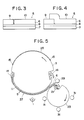
- Figure 3 shows a schematic side view of an iamge-forming material 5 comprising a substrate 7, a photosenstive layer 8 and a protective film 6, in which the protective film 6 has a cut in the terminal portion 9, and the terminal portion to be gripped by a clamp bar and the remaining portion of the protective film are cut apart or separated. Due to the cut, the terminal portion of the protective film is conveyed to the pressure cylinder, and the remaining protective film remains attached to the exposure cylinder. In this case, it is preferable that the protective film on the photosensitive layer side has been treated for release.
- Figure 4 shows a state in which the protective film 6 is cut in the terminal portion 9 and the remaining portion of the protective film is overlaid on the terminal portion. Consequently, only the terminal portion is conveyed to the pressure cylinder while being held by the clamp bar, and the remaining portion of the protective film remains attached to the exposure cylinder.
- Figure 5 is a schematic side view of another embodiment of the apparatus for forming an image in this invention, in which the apparatus comprises a light source for exposure, an exposure cylinder and a pressure cylinder, and a protective film is separated on the pressure cylinder side.
- a U.V. lamp 1 is disposed radially outside an exposure cylinder 3, and a lamiante 37 composed of an image-forming mateial 5 and an original image 11 is exposed to the U.V. lamp.
- the exposure cylinder is provided with a gripper 14 for the attachment of the iamge-forming mateial in the concave portion and with an adhesive tape 15 for the attachment of the iamge-forming material.
- the gripper 14 may be selected from those generally used in pressure and intermdediate cylinders of a printing machine to shift a grip.
- the exposure cylinder 3 is rotated to introduce the laminate of the image-forming material 5 and the original image 11 into the nip formed between the exposure cylinder 3 and a pressure cylinder 23. It is also possible to separate the original image from the laminate after exposure and introduce the image-forming material into the nip by arranging the attaching means and holding means as shown in Figure 1.
- the pressure cylinder 23 is provided with a gripper 21 having an arm in a surface portion in which to hold the image-forming material, and the gripper 21 is to hold the introduced image-forming material.
- a protective film 6 has a cut in the vicinity of its leading end portion on the pressure cylinder as shown in Figure 3 or 4.
- the gripper 21 holds the image-forming material including the terminal portion of the protective film a and the arm swings to turn the gripper, then, the protective film is separated by holding the remaining terminal portion of the protective film.
- the separated protective film is taken by a take-up roller 29.
- the gripper 21 having the arm and a hold roll 31 hold the image-forming material from which the protective film is separated.
- the image-forming material held on the surface of the pressure cylinder and having a photosensitive layer on its surface is introduced to the nip formed between the pressure cylinder and the exposure cylinder by rotating the pressure cylinder, and brought into contact, under pressure, with an image receptor 25 attached to the exposure cylinder with an adhesive tape provided to the exposure cylinder, to transfer an image formed on the photosensitive layer to the image receptor. After the transfer, it is preferable to release the pressure cylinder from the contact to the exposure cylinder. It is also preferable that the exposure cylinder is provided with heating means (not shown) in the portion to which the image receptor is attached. It is further preferable to turn the exposure cylinder to carry out the post-exposure of the transferred image.
- Figure 6 is a schematic side view of another embodiment of the apparatus for forming an image in this invention, which comprises a light source for exposure, an exposure cylinder, a pressure cylinder and a common transfer cylinder.
- a U.V. lamp 1 is arranged outside the radious of the an exposure cylinder 3.
- a lamiante 37 composed of an image-forming material 5 and an original image 11, laminated in this order, is laid on the exposure cylinder such that the protective film is on the exposure cylinder side, and exposed to the U.V. lamp 1.
- the exposure cylinder 3 is provided with suction means of holding the laminate 37.
- the suction means stands for many holes formed in the portion of the exposure cylinder to which the image-forming material is to be attached, and holds the image-forming material by suction.
- the area of the image-forming material 5 may be smaller than that of the orginal image 11 so that suction may be exerted on the original image.
- the original iamge 11 is brough into intimate contact with the image-forming material by using a top sheet 33, which is square-shaped, larger-sized, empty in the middle portion and held by suction, on the laminate 37.
- the suction means may be divided into a plurality of groups, and each group may be worked independently.
- the original image 11 and the top sheet 33 are separated from the exposed laminate 37, and then the exposure cylinder 3 is turned to introduce the image-forming material into the nip formed between the exposure cylinder 3 and a pressure cylinder 23.
- Grip-shifting means such as a gripper, etc., may be used to convey the laminate onto the pressure cylinder without separating the original image from the laminate.
- the image-forming material introduced is attached to the pressure cylinder 23 with a duplicated adhesive tape 25 provided to the portion of the surface of the pressure cylinder to which the image-forming material is to be attached, and the protective film 6 is separated on the pressure cylinder.
- the protective film 6 may be retained on the surface of the exposure cylinder.
- the image-forming material from which the protective film is separated and which is attached to the surface of the pressure cylinder is introduced in the nip formed between the pressure cylinder and the common transfer cylinder by rotating the pressure cylinder, and brought into contact under pressure with an image receptor 25 held on the common transfer cylinder with a gripper 14 formed in the concave portion of the common transfer cylinder and suction means 13, to transfer an image formed in the photosensitive layer into the image receptor.
- the image receptor 25 may be attached by using a duplicated adhesive tape. It is preferable to release the pressure cylinder from its contact to the common transfer cylinder after the transfer. It is also preferable that the common transfer cylinder is provided with heating means (not shown) in the portion where the image receptor is to be attached.
- the common transfer cylinder is further turned to carry out the post-exposure of the transferred image to the U.V. lamp 1.
- a color prepress proof or color printed matter can be obtained.
- the image receptor can be selected from art paper, coated paper, wood free paper, films, and the like.
- the original image is a film processed for a single color (image mask) or an image mask obtained by fixing a shade paper to a transparent polyethylene terephthalate film having functions of color separation, etc., when it is used for a single color prepress proof or printed matter, and a color-separated image mask is used for a multicolor proof or printed matter.
- the image-forming material for this invention comprises a substrate, a photosensitive layer formed on one surface of the substrate and a protective film.
- the substrate suitably usable are materials which are statble against heat, chemicals, lights, etc., and which are permeable to active beams, e.g. a film or sheet of cellulose acetate, polystyrene, polyvinyl chloride, polyethylene terephthalate, polycarbonate, polyimide or polypropylene.
- a polyethylene terephthalate film or sheet is excellent in transparency, thermal stability and dimensional stability, and preferable.
- the above substrates may be used without any modification, or treated for release with a suitable oil-repellent substance such as silicon resin, fluorine resin, etc.
- the photosensitive layer has a consitution of:
- a photopolymerization initiator, an inhibitor of thermal polymerization, etc., may be further used in combination.
- the photopolymerizable compound at least one selected from monomer, oligomer and prepolymer is used.
- Preferably usable is a compound which can plasticize the thermoplastic resin at room temperature.
- thermoplastic resin organic polymer binder
- thermoplastic resin organic polymer binder
- dyes and/or pigments are usable as dyes and/or pigments in the photosensitive layer.
- dyes and/or pigments having hues of yellow, magenta, cyan and black are desirable, and metallic powders, white pigments, fluorescent pigments are also usable as well.
- the photosensitive layer has a film thickness of about 0.5 ⁇ m to 5 ⁇ m.
- the suitably applied amount therefor depends on dyes and/or pigments, and is suitably in the range of from 0.5 g/m2 to 10 g/m2.
- the protective film it is possible to cite a polyethylene film, polyethylene terephthalate film and acetate film.
- a polyethylene film is used as a protective film, releasability of the polyethylene film may be utilized, or a releasing agent, e.g. silicon resin may be applied on the protective film.
- the transfer of an image to the image receptor may be carried out by introduction to the nip formed between an exposure cylinder to which the image receptor is attached and a pressure cylinder.
- the transfer of an image to the image receptor may be carried out by introduction to the nip formed between a transfer cylinder to which the image receptor is attached and a pressure cylinder.
- This invention is applicable not only to an overlay method but also to small-volune printing up to about some hundreds copies.
- This invention gives transfer images having excellent quality, gives a normal image in one transfer, makes it possible to carry out exposure and transfer continuously, and makes it easy to carry out registering. Therefore, this invention produces a remarkable effect that stable images can be obtained without counting on skilled workers' experience and special sense.
- the protective film has a larger thickness and a poorer permeability to light than the substrate.
- the image-forming material and iamge receptor can be attached to an exposure cylinder, it is relatively easy to carry out registering, and it is therefore possible to provide prepress proof or printed matter free from register failure.
- pressure and exposure cylinders are arranged in the circumferential area of a common transfer cylinder and each of colors are transferred nearly at the same time, it is relatively easy to carry out registering, and it is therefore possible to provide color proof or printed matter free from registering failure.
- a liquid for a photosensitive layer having the following composition was prepared.
- Diallylisophthalate prepolymer (Daiso Isodap Mn 45000, trade name, made by Toyo Soda Co., Ltd.): 21.23 parts Dipentaerythritolhexaacrylate (DPHA, trade name, made by Nippon Kayaku K.K.): 7.08 parts Photopolymerization initiator, benzophenone: 0.5 part.
- the above liquid was applied on a biaxially oriented polyethylene terephthalate film (having a thickness of 12 ⁇ m) such that its dried thickness was 2.4 ⁇ m. Then, a polyethylene film (as a protective film) was attached onto the coated surface thereof to give an image-forming material.
- the image-forming material, a positive film and a sheet of art paper were respectively attached onto the exposure cylinder of an apparatus shown in Figure 1, and exposure and transfer were carried out.
- the positive film was manually separated after the exposure.
- the protective film was smoothly separated from the image-forming material, and the resultant image was clear.
- the rate of feeding the image-forming material and the art paper sheet to the nip portion was 50 cm/minute, the linear pressure was 7 kgf/cm, and the exposure cylinder had a surface temperature, on the art paper side, of 100°C.
- Example 1 The procedure for the preparation of the liquid for a photosensitve layer in Example 1 was repeated to prepare three liquids for a photosensitive layer except that Lionol yellow FG1310 (trade name, made by Toyo Ink Manufacturing Co., Ltd.), Carmine 7BFG (trade name, made by Toyo Ink Manufacturing Co., Ltd.) and Lionol Blue FG7330 (trade name, made by Toyo Ink Manufacturing Co., Ltd.) were used in place of the carbon black in Example 1.
- Lionol yellow FG1310 trade name, made by Toyo Ink Manufacturing Co., Ltd.
- Carmine 7BFG trade name, made by Toyo Ink Manufacturing Co., Ltd.
- Lionol Blue FG7330 trade name, made by Toyo Ink Manufacturing Co., Ltd.
- the liquids were respectively applied on polyethylene terephthalate films in the same way as in Example 1, and a polyethylene film was attached to each of the coated surfaces to give image-forming materials.
- a color-separated positive film corresponding to Lionol Yellow FG1310 was laminated on the image-forming material, and the laminate was exposed by using the apparatus shown in Figure 1 and laid on the transfer image obtained in Example 1 to carry out transfer. Then, the above procedure was also repeated with regard to the remaining colors to prepare a color proof in which a dot image was formed in the order of black, yellow, cyan and magenta.
- Example 2 The same image-forming material as that of Example 1 and a positive film were attached onto the exposure cylinder of an apparatus shown in Figure 5 with the protective film of the material on the exposure cylinder side, and an art paper sheet was also attached on the exposure cylinder. Then exposure and transfer were carried out.
- the protective film having a cut in the terminal portion was used.
- the terminal portion floated with an action of a gripper 21 with an arm was attached to a take-up roller 29, and the take-up roller was turned to separate the protective film from the image-forming material.
- Example 3 The procedure of Example 3 was repeated to prepare a color proof except that the same image-forming material as that of Example 2 was used and that transfer was carried out on the transfer image obtained in Example 3 in the order of black, cyan, magenta and yellow.
- Example 1 and 2 The same image-forming materials as those of Example 1 and 2 and color-separated positive films corresponding to black, cyan, magenta and yellow were attached to the exposure cylinders of an apparatus shown in Figure 6, and transfer was carried out in the order of black, cyan, magenta and yellow.
- the exposed positive films were separated on the exposure cylinders.
- Each of the protective films was separated from the image-forming material in the nip formed between the exposure cylinder and the pressure cylinder. The resultant transfer image was clear.
- the rate of feeding the image-forming material and the art paper sheet into the nip in each case was 50 cm/minute, the linear pressure was 7 kgf/cm, and the surface temperature of each of the exposure cylinders on the art paper side was 100°C.
Landscapes
- Physics & Mathematics (AREA)
- General Physics & Mathematics (AREA)
- Photosensitive Polymer And Photoresist Processing (AREA)
- Exposure And Positioning Against Photoresist Photosensitive Materials (AREA)
Applications Claiming Priority (6)
| Application Number | Priority Date | Filing Date | Title |
|---|---|---|---|
| JP164984/88 | 1988-07-04 | ||
| JP164986/88 | 1988-07-04 | ||
| JP164985/88 | 1988-07-04 | ||
| JP16498688A JPH0664334B2 (ja) | 1988-07-04 | 1988-07-04 | 画像形成装置および画像形成方法 |
| JP63164985A JPH0627943B2 (ja) | 1988-07-04 | 1988-07-04 | 画像形成装置および画像形成方法 |
| JP16498488A JPH0215259A (ja) | 1988-07-04 | 1988-07-04 | 画像形成装置および画像形成方法 |
Publications (2)
| Publication Number | Publication Date |
|---|---|
| EP0350195A2 true EP0350195A2 (fr) | 1990-01-10 |
| EP0350195A3 EP0350195A3 (fr) | 1991-04-03 |
Family
ID=27322416
Family Applications (1)
| Application Number | Title | Priority Date | Filing Date |
|---|---|---|---|
| EP19890306530 Withdrawn EP0350195A3 (fr) | 1988-07-04 | 1989-06-27 | Procédé et appareil pour l'obtention d'images |
Country Status (3)
| Country | Link |
|---|---|
| US (1) | US5019860A (fr) |
| EP (1) | EP0350195A3 (fr) |
| AU (1) | AU610414B2 (fr) |
Cited By (7)
| Publication number | Priority date | Publication date | Assignee | Title |
|---|---|---|---|---|
| EP0593780A1 (fr) * | 1992-04-13 | 1994-04-27 | Toyo Ink Manufacturing Co., Ltd. | Appareil de transfert d'image |
| EP0601188A1 (fr) * | 1992-04-13 | 1994-06-15 | Toyo Ink Manufacturing Co., Ltd. | Appareil de transfert d'images et procede pour ejecter des supports d'images |
| EP0614119A1 (fr) * | 1993-03-03 | 1994-09-07 | Fuji Photo Film Co., Ltd. | Dispositif de formation d'image et méthode |
| EP0616257A2 (fr) * | 1993-03-18 | 1994-09-21 | Toyo Ink Manufacturing Co., Ltd. | Procédé et méthode pour le transfert de l'image |
| BE1008502A3 (nl) * | 1994-07-18 | 1996-05-07 | Agfa Gevaert Nv | Delaminator voor een droog verwerkbaar beeld. |
| US5573888A (en) * | 1993-03-18 | 1996-11-12 | Toyo Ink Manufacturing Co., Ltd. | Image transfer method |
| EP0754558A1 (fr) * | 1995-07-19 | 1997-01-22 | Minnesota Mining And Manufacturing Company | Appareil et méthode pour le contact entre donneur et récepteur d'image dans une imprimante par transfer thermique induit par laser |
Families Citing this family (2)
| Publication number | Priority date | Publication date | Assignee | Title |
|---|---|---|---|---|
| EP0593781B1 (fr) * | 1992-04-13 | 1998-07-08 | Toyo Ink Manufacturing Co., Ltd. | Appareil de transfert d'images |
| JP7052150B2 (ja) * | 2018-11-18 | 2022-04-11 | ランダ コーポレイション リミテッド | 基材の非印刷マージンの低減によるデジタル印刷システムの印刷出力の改善 |
Citations (1)
| Publication number | Priority date | Publication date | Assignee | Title |
|---|---|---|---|---|
| US3431846A (en) * | 1966-07-28 | 1969-03-11 | Du Pont | Offset image transfer process |
Family Cites Families (3)
| Publication number | Priority date | Publication date | Assignee | Title |
|---|---|---|---|---|
| JPS55113080A (en) * | 1979-02-25 | 1980-09-01 | Konishiroku Photo Ind Co Ltd | Master sheet mounting and dismounting device of drum |
| JPS61118783A (ja) * | 1984-11-14 | 1986-06-06 | Fujiretsukusu Kk | ドラムに感光体フイルムを巻き付ける方法 |
| JPS61133768A (ja) * | 1984-12-03 | 1986-06-21 | Dainippon Screen Mfg Co Ltd | ドラム型画像走査記録装置 |
-
1989
- 1989-06-27 EP EP19890306530 patent/EP0350195A3/fr not_active Withdrawn
- 1989-06-27 US US07/371,972 patent/US5019860A/en not_active Expired - Fee Related
- 1989-06-28 AU AU37148/89A patent/AU610414B2/en not_active Ceased
Patent Citations (1)
| Publication number | Priority date | Publication date | Assignee | Title |
|---|---|---|---|---|
| US3431846A (en) * | 1966-07-28 | 1969-03-11 | Du Pont | Offset image transfer process |
Cited By (15)
| Publication number | Priority date | Publication date | Assignee | Title |
|---|---|---|---|---|
| US5402727A (en) * | 1992-04-13 | 1995-04-04 | Toyo Ink Manufacturing Co., Ltd. | Image transfer apparatus and method for ejecting image receptor |
| US5503075A (en) * | 1992-04-13 | 1996-04-02 | Toyo Ink Manufacturing Co., Ltd. | Image transfer apparatus and method for ejecting image receptor |
| EP0593780A4 (fr) * | 1992-04-13 | 1994-08-03 | Tokyo Ink Manufacturing Co., | |
| EP0601188A4 (fr) * | 1992-04-13 | 1994-08-03 | Tokyo Ink Manufacturing Co., | |
| US5533451A (en) * | 1992-04-13 | 1996-07-09 | Toyo Ink Manufacturing Co., Ltd. | Image transfer apparatus with transfer drum clamping mechanism |
| EP0593780A1 (fr) * | 1992-04-13 | 1994-04-27 | Toyo Ink Manufacturing Co., Ltd. | Appareil de transfert d'image |
| EP0601188A1 (fr) * | 1992-04-13 | 1994-06-15 | Toyo Ink Manufacturing Co., Ltd. | Appareil de transfert d'images et procede pour ejecter des supports d'images |
| EP0614119A1 (fr) * | 1993-03-03 | 1994-09-07 | Fuji Photo Film Co., Ltd. | Dispositif de formation d'image et méthode |
| US5532722A (en) * | 1993-03-03 | 1996-07-02 | Fuji Photo Film Co., Ltd. | Image forming device and method for transferring ink using a heated pneumatic drum |
| EP0616257A2 (fr) * | 1993-03-18 | 1994-09-21 | Toyo Ink Manufacturing Co., Ltd. | Procédé et méthode pour le transfert de l'image |
| EP0616257A3 (fr) * | 1993-03-18 | 1995-04-26 | Toyo Ink Mfg Co | Procédé et méthode pour le transfert de l'image. |
| US5573888A (en) * | 1993-03-18 | 1996-11-12 | Toyo Ink Manufacturing Co., Ltd. | Image transfer method |
| BE1008502A3 (nl) * | 1994-07-18 | 1996-05-07 | Agfa Gevaert Nv | Delaminator voor een droog verwerkbaar beeld. |
| EP0754558A1 (fr) * | 1995-07-19 | 1997-01-22 | Minnesota Mining And Manufacturing Company | Appareil et méthode pour le contact entre donneur et récepteur d'image dans une imprimante par transfer thermique induit par laser |
| US5764268A (en) * | 1995-07-19 | 1998-06-09 | Imation Corp. | Apparatus and method for providing donor-receptor contact in a laser-induced thermal transfer printer |
Also Published As
| Publication number | Publication date |
|---|---|
| US5019860A (en) | 1991-05-28 |
| EP0350195A3 (fr) | 1991-04-03 |
| AU3714889A (en) | 1990-01-11 |
| AU610414B2 (en) | 1991-05-16 |
Similar Documents
| Publication | Publication Date | Title |
|---|---|---|
| US4376159A (en) | Method of preparing matte finish color-proofing surprints | |
| US4656114A (en) | Presensitized color-proofing diazo resin sheet with acrylic thermal adhesive layer | |
| US5019860A (en) | Apparatus for image formation and method of image formation | |
| EP0550338A1 (fr) | Feuille pour épreuve en couleurs présensibilisée | |
| US5240810A (en) | Pre-press proofing method | |
| CA1255956A (fr) | Epreuve d'impression en couleurs prechromatisee | |
| GB2213950A (en) | A method of image formation and an image-forming material | |
| JPH02123360A (ja) | 画像形成材料 | |
| JPH01172957A (ja) | 画像形成装置 | |
| EP0584406B1 (fr) | Procédé de trans-laminage | |
| US5055375A (en) | Method of image formation using heated rollers | |
| EP0403128A2 (fr) | Epreuve en couleurs | |
| EP0327883A2 (fr) | Système monocouche positif ou négatif pour l'épreuve des couleurs | |
| JP2887312B2 (ja) | 画像形成方法 | |
| JP2573705B2 (ja) | 画像形成装置 | |
| JPH081862Y2 (ja) | 画像形成装置 | |
| JPH01172947A (ja) | 画像形成材料 | |
| JPH03129354A (ja) | 画像形成装置および重ね刷り方法 | |
| JPH0664334B2 (ja) | 画像形成装置および画像形成方法 | |
| JPH0642062B2 (ja) | 画像形成装置および画像形成方法 | |
| JP2629043B2 (ja) | 画像形成材料 | |
| JP2595355B2 (ja) | 画像形成方法 | |
| JPH0215262A (ja) | 画像形成装置および画像形成方法 | |
| JPH0333750A (ja) | 画像形成装置および画像形成方法 | |
| JPH0266553A (ja) | 画像形成方法 |
Legal Events
| Date | Code | Title | Description |
|---|---|---|---|
| PUAI | Public reference made under article 153(3) epc to a published international application that has entered the european phase |
Free format text: ORIGINAL CODE: 0009012 |
|
| AK | Designated contracting states |
Kind code of ref document: A2 Designated state(s): DE FR GB |
|
| RAP1 | Party data changed (applicant data changed or rights of an application transferred) |
Owner name: TOYO INK MANUFACTURING CO., LTD. |
|
| PUAL | Search report despatched |
Free format text: ORIGINAL CODE: 0009013 |
|
| AK | Designated contracting states |
Kind code of ref document: A3 Designated state(s): DE FR GB |
|
| 17P | Request for examination filed |
Effective date: 19910628 |
|
| STAA | Information on the status of an ep patent application or granted ep patent |
Free format text: STATUS: THE APPLICATION HAS BEEN WITHDRAWN |
|
| 18W | Application withdrawn |
Withdrawal date: 19920427 |