EP0349992B1 - Rear wheel turning system for a vehicle - Google Patents
Rear wheel turning system for a vehicle Download PDFInfo
- Publication number
- EP0349992B1 EP0349992B1 EP89112222A EP89112222A EP0349992B1 EP 0349992 B1 EP0349992 B1 EP 0349992B1 EP 89112222 A EP89112222 A EP 89112222A EP 89112222 A EP89112222 A EP 89112222A EP 0349992 B1 EP0349992 B1 EP 0349992B1
- Authority
- EP
- European Patent Office
- Prior art keywords
- control
- wheel turning
- engine
- rear wheel
- vehicle
- Prior art date
- Legal status (The legal status is an assumption and is not a legal conclusion. Google has not performed a legal analysis and makes no representation as to the accuracy of the status listed.)
- Expired - Lifetime
Links
Images


Classifications
-
- B—PERFORMING OPERATIONS; TRANSPORTING
- B62—LAND VEHICLES FOR TRAVELLING OTHERWISE THAN ON RAILS
- B62D—MOTOR VEHICLES; TRAILERS
- B62D7/00—Steering linkage; Stub axles or their mountings
- B62D7/06—Steering linkage; Stub axles or their mountings for individually-pivoted wheels, e.g. on king-pins
- B62D7/14—Steering linkage; Stub axles or their mountings for individually-pivoted wheels, e.g. on king-pins the pivotal axes being situated in more than one plane transverse to the longitudinal centre line of the vehicle, e.g. all-wheel steering
- B62D7/148—Steering linkage; Stub axles or their mountings for individually-pivoted wheels, e.g. on king-pins the pivotal axes being situated in more than one plane transverse to the longitudinal centre line of the vehicle, e.g. all-wheel steering provided with safety devices
Definitions
- This invention relates to a rear wheel turning system for a vehicle having the features of the respective first part of claims 1, 5 and 7.
- a four-wheel-steered vehicle is provided with a four-wheel steering system which comprises a rear wheel turning system for turning the rear wheels and a front wheel turning system for turning the front wheels.
- the rear wheels are turned by an actuator which is driven by the engine output power of the vehicle
- the rear wheels are turned by an actuator which is driven by a battery mounted on the vehicle.
- the rear wheel turning system disclosed in U.S. Patent No. 4,732,231 comprises a hydraulic power cylinder which turns the rear wheels with the hydraulic pressure provided thereto from a hydraulic pump. The pressure is controlled by means of a control valve, and the hydraulic pump is driven by the engine.
- a rear wheel neutralizing means which comprises a centering spring and urges the rear wheels toward the neutral position, i.e., the straight-ahead position.
- the rear wheel neutralizing means returns the rear wheels to the straight-ahead position, and thereafter the vehicle is made to behave as a two-wheel-steered vehicle.
- the rear wheels are turned in a direction opposite to the turning direction of the front wheels when the vehicle is running at a low speed in order to improve the heading performance and in the same direction as the turning direction of the front wheels when the vehicle is running at a high speed in order to improve the driving stability.
- the vehicle is not generally braked at once and is allowed to run by inertia for a while. Since the rear wheels are returned to the straight-ahead position as soon as the engine stalls, the turning radius will become larger and and the vehicle will follow a larger arc, which can cause an accident.
- the control system controls an automatic transmission of the vehicle
- the self-holding circuit holds the power supply.
- signals are read in from an engine rotation sensor and from a vehicle speed sensor. Until these signals indicate that the engine and the vehicle are stopped, the control system continuously delivers an appropriate signal to the transmission control unit to control the running of the vehicle, while preventing undesired accidents from occurring due to an unexpected cut off of the electric power during travel of the vehicle.
- the primary object of the present invention is to provide a rear wheel turning system in which the rear wheels are turned by an actuator driven by a battery and which is free from the problems that occur when the vehicle is made to behave as a two- wheel -steered vehicle as soon as the engine stalls or when the vehicle is kept in a stalled state for a long time and the battery dies.
- the rear wheel turning system continues functioning of the rear wheel turning mechanism only until a predetermined condition is established and thereafter ceases the power supply to the battery.
- this predetermined condition is established when the turning angle of the front wheels is zero. At that time the rear wheels are held in the straight-ahead position so that the vehicle behaves as a two-wheel-steered vehicle until the engine is restarted, for example.
- the control means may continue to control the electric motor as before, as according to the first aspect of the invention, (the type of control performed by the control means when the engine is operating normally will be designated the normal control) or may control the electric motor in a different way as according to a second aspect of the invention.
- the control means shifts to a convergence control in which the target rear wheel turning angles to which the rear wheels are to be turned during the normal control are multiplied by a coefficient which gradually decreases from 1 to 0 over time, and the values thus obtained are adopted as the target rear wheel turning angles.
- the control means may shift to carrying out the convergence control either as soon as the engine stall detecting means outputs the detecting signal or a predetermined time after the same.
- the control means shifts to the convergence control it may be considered that the predetermined condition is established when said coefficient becomes 0 and the rear wheel turning angle becomes 0, i.e., when control according to the convergence control is completed.
- the control means shifts to carrying out the convergence type of control after the engine stalls, the rear wheels can be positively returned to the straight-ahead position even if the front wheel turning angle does not become zero for a long time, and accordingly, because the rear wheels being in a straight-ahead position is adopted as the predetermined condition, the battery can certainly be prevented from dying and the control of the rear wheels can be smoothly interrupted without any adverse effects.
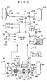
- a four-wheel steered vehicle is provided with a front wheel turning mechanism 14 for turning left and right front wheels 12L and 12R and a rear wheel turning mechanism 16 for turning left and right rear wheels 16L and 16R in accordance with an embodiment of the present invention.
- the front wheel turning mechanism 14 comprises a front wheel turning rod 22 provided with a rack (not shown in Figure 1) in mesh with a pinion 24 on the lower end of a steering shaft 28.
- a steering wheel 26 is mounted on the upper end of the steering shaft 28.
- the left front wheel 12L is connected to the left end of the front wheel turning rod 22 by way of a left tie rod 18L and a left knuckle arm 20L
- a right front wheel 12R is connected to the right end of the front wheel turning rod 22 by way of a right tie rod 18R and a right knuckle arm 20R.
- the front wheel turning rod 22 is displaced in the transverse direction of the vehicle body and the front wheels 12L and 12R are turned.
- the rear wheel turning mechanism 16 comprises a rear wheel turning rod 30, a servomotor 4, a ball-screw means 40 which is rotated by the servomotor 4 and displaces the rear wheel turning rod 30 in the transverse direction of the vehicle body, a centering spring means 38 which urges the rear wheel turning rod 30 into the neutral position and a control unit 10 which controls the servomotor 4.
- An engine-stall detecting means 8 which detects whether the engine of the vehicle has stalled and outputs an engine stall signal when the engine has stalled is connected to the control unit 10, and other various information input means which will become apparent later are connected to the control unit 10.
- the rear wheel turning rod 30 extends in the transverse direction of the vehicle body.
- the left rear wheel 6L is connected to the left end of the rear wheel turning rod 30 by way of a knuckle arm 36L and a tie rod 46L
- the right rear wheel 6R is connected to the right end of the rear wheel turning rod 30 by way of a knuckle arm 36R and a tie rod 46R so that the left and right rear wheels 6L and 6R are turned in response to a displacement of the rear wheel turning rod 30 in the transverse direction of the vehicle body.
- the rear wheel turning rod 30 is displaced in the transverse direction of the vehicle body by the servomotor 4.
- the servomotor 4 is a stepping motor, and is connected to the rear wheel turning rod 30 by way of a driving force transmitting system comprising a brake 40, a double clutch mechanism 42, a reduction gear train 44 and the ball screw-means 40.
- the servomotor 4 displaces the rear wheel turning rod 30 in the transverse direction of the vehicle body from the neutral position, overcoming the force of the centering spring means 38.
- the brake 40 holds the rear wheel turning rod 30 in a predetermined position by locking the driving force transmitting system between the servomotor 4 and the rear wheel turning rod 30 in response to a control signal from the control unit 10. While the steering wheel 26 is fixed, that is, when the target turning angle of the rear wheels is fixed, the rear wheel turning rod 30 should be held in a predetermined position. When the rear wheel turning rod 30 is fixed by the brake 40, the power consumption can be reduced as compared with when it is fixed by the servomotor 4.
- the brake 40 comprises an electro-magnetic brake which locks the output shaft of the servomotor 4.
- the double clutch mechanism 42 cuts the driving force transmitting system between the servomotor 4 and the rear wheel turning rod 30 and disconnects the rear wheel turning rod 30 from the servomotor 4 in response to a control signal from the control unit 10 as will be described in detail later, thereby permitting the rear wheel turning rod 30 to return to the neutral position under the force of the centering spring means 38.
- the double clutch mechanism 42 comprises a pair of electro-magnetic clutches 42A and 42B disposed in series with each other.
- the clutch 42A nearer to the servomotor 4 is of a normally-open type which is normally disengaged and is engaged when it is energized, and the other clutch 42B is of a normally-closed type which is normally engaged and is disengaged when it is energized.
- the rear wheel turning means can be disconnected from the electric motor even if one of the clutches is unable to disengage.
- the provision of a pair of clutches allows the rear wheels to be returned to the straight-ahead position with a higher reliability in case the rear-wheel turning system fails.
- one of the clutches is a normally-closed type of electro-magnetic clutch and the other clutch is a normally-open type of electro-magnetic clutch, the reliability of the system can be further improved and at the same time, the power consumption can be reduced.
- the ball-screw means 46 comprises a ball nut 48, a ball thread 50 cut on the rear wheel turning rod 30 and balls 52 interposed between the ball nut 48 and the ball thread 50.
- the ball nut 48 is fixed to a gear 54 which is in mesh with the reduction gear train 44.
- the ball nut 48 cannot be displaced in the longitudinal direction of the rear wheel turning rod 30 though it can rotate together with the gear 54. With this arrangement, the rear wheel turning rod 30 is displaced in the longitudinal direction thereof in response to the rotation of the output shaft of the servomotor 32.
- the centering spring means 38 includes a pair of stoppers 56 and 58 disposed on the rear wheel turning rod 30 at a predetermined distance from each other.
- a pair of spring retainers 60 and 62 are slidably fitted on the rear wheel turning rod 30 between the stoppers 56 and 58, and a centering spring 64 is compressed between the spring retainers 60 and 62.
- the rear wheel turning rod 30 extends through the centering spring 64.
- a pair of stoppers 66 and 68 are formed on the inner side of the housing.
- the spring retainer 60 abuts against both the stopper 56 on the rear wheel turning rod 30 and the stopper 66 on the housing under the force of the centering spring 64, and the spring retainer 62 abuts against both the stopper 58 on the rear wheel turning rod 30 and the stopper 68 on the housing under the force of the centering spring 64.
- the rear wheel turning rod 30 is normally urged into the neutral position by the compression load (preset load) on the centering spring 64.
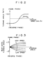
- control unit 10 controls the rear wheel turning mechanism 16 according to the running condition of the vehicle on the basis of predetermined four-wheel steering characteristics.
- the control unit 10 controls the rear wheel turning mechanism 16 so that the rear wheel turning angle ratio, i.e., the ratio of the turning angle of the rear wheels to the ratio of the turning angle of the front wheels, is changed according to the vehicle speed and the turning angle of the steering wheel 26 on the basis of the four-wheel steering characteristics shown in Figures 2 and 3.
- the rear wheel turning angle ratio is defined to be positive when the rear wheels are turned in the same direction as the front wheels (same phase) and to be negative when the rear wheels are turned in the direction opposite to that of the front wheels (reverse phase).
- the control unit 10 receives signals from a vehicle speed detecting means 70, a front wheel turning angle detecting means 72 and a rotary encoder 74 which detects the angular position of the servomotor 4, and determines a target rear wheel turning angle on the basis of the front wheel turning angle and the vehicle speed. Then the control unit 10 outputs a control signal to the servomotor 4, which control signal represents the amount by which the rear wheels are to be turned, and the rotary encoder 74 watches whether the servomotor 4 is correctly operated.
- the control unit 10 controls the brake 40 and the double clutch mechanism 42 in addition to the servomotor 32.
- the control unit 10 causes the brake 40 to lock the output shaft of the servomotor 4. Thereby the brake 40 holds the rear wheel turning rod 30 in the predetermined position corresponding to the target rear wheel turning angle so long as the rear wheel turning system is normal.
- the control unit 10 disengages the double clutch mechanism 42, which permits the rear wheel turning rod 30 to return to the neutral position under the force of the centering spring means 38.
- a first measure mode or a second measure mode is taken according to the kind of failure which occurs.
- the first measure mode is taken in the case of a failure such as one that disables the control of the rear wheels 6L and 6R by the servomotor 4, e.g., a failure in the servomotor 4, the control unit 4, the rotary encoder 74 or the like.
- a failure such as one that disables the control of the rear wheels 6L and 6R by the servomotor 4, e.g., a failure in the servomotor 4, the control unit 4, the rotary encoder 74 or the like.
- the double clutch mechanism 42 is disengaged and the rear wheels are returned to the straight-ahead position under the force of the centering spring means 38.
- the second measure mode is taken in the case of a failure such as one that does not permit correct four-wheel steering control but permits turning of the rear wheels and detection of the position of the rear wheels, e.g., a failure in the vehicle speed sensor 70, the front wheel turning angle sensor 72 and the like.
- a failure such as one that does not permit correct four-wheel steering control but permits turning of the rear wheels and detection of the position of the rear wheels, e.g., a failure in the vehicle speed sensor 70, the front wheel turning angle sensor 72 and the like.
- the rear wheels are turned to the straight-ahead position by the servomotor 4.
- the control unit 10 further effects a delay type of control and a phase inverting type of control. That is, with the delay type of control, the rear wheels are turned in the same direction as the turning direction of the front wheels a predetermined time after the front wheels are turned when the front wheels and the rear wheels are to be turned in the same phase, and with the phase inverting type of control, the rear wheels are first turned in the direction opposite to the turning direction of the front wheels for a predetermined time and then are turned in the same direction as the turning direction of the front wheels. Either of the delay type of control or the phase inverting type of control serves to compensate for the deterioration in the heading performance which would occur if the front wheels and the rear wheels were simultaneously turned in the same direction.
- the vehicle speed detecting means 70 comprises first and second vehicle speed sensors 70A and 70B, and the front wheel turning angle detecting means 70 comprises a first front wheel turning angle sensor 72A which detects the turning angle of the steering wheel 26 and a second front wheel turning angle sensor 72B which detects the displacement of the front wheel turning rod 22.
- the turning angle of the front wheels is then determined from the turning angle of the steering wheel 26.
- the turning angle of the front wheels is also determined from the displacement of the front wheel turning rod 22.
- a rear wheel turning angle sensor 76 which detects the displacement of the rear wheel turning rod 30 is provided in addition to the rotary encoder 74 which detects the angular position of the servomotor 4.
- the turning angle of the rear wheels is determined, and from the angular position of the servomotor 4 the turning angle of the rear wheels is also determined. That is, the vehicle speed, the front wheel turning angle and the rear wheel turning angle are doubly detected, whereby various failures in the rear wheel turning system can surely be detected when they occur, and the reliability of the system can be improved. Further, on-off signals from a neutral clutch switch 78, an inhibitor switch 80, a brake switch 82 and an ignition switch 84 are input into the control unit 10, and a signal which represents whether or not an alternator is generating electricity is input into the control unit 10 from an L-terminal of the alternator. Reference numeral 88 denotes a warning lamp which is lit when any failure occurs in the system.
- the engine stall detecting means 8 inputs a detecting signal which represents that the engine has stalled into the control unit 10, and the control unit 10 ceases operation when a predetermined condition is established after the engine stall detecting means 8 outputs the detecting signal.
- the engine stall detecting means 8 may comprise a microprocessor which determines whether the engine has stalled on the basis of whether the ignition switch 84 is on and whether the output of the L-terminal 86 of the alternator is low as shown in Figure 4, or on the basis of whether the vehicle speed is zero and whether the output of the L-terminal 86 of the alternator is low as shown in Figure 5. In the former arrangement, the engine stall detecting means 8 determines that the engine has stalled when the ignition switch 84 is on and the output of the L-terminal 86 of the alternator is low, and outputs the detecting signal.
- the engine stall detecting means 8 determines that the engine has stalled when the vehicle speed is not zero and the output of the L-terminal 86 of the alternator is low, and outputs the detecting signal. In accordance with the latter arrangement, the engine stall detecting means 8 outputs the detecting signal even when the driver intentionally turns off the ignition switch 84 and the vehicle is running by inertia, such as when the vehicle is running downhill. In this specification, the engine should be considered to be “stalled” even when the ignition switch is turned off while the vehicle is running at a certain speed by inertia.
- Figure 6 shows an example of the operations performed by the control unit 10 after the engine has stalled.
- step S1 the control unit 10 determines in step S1 whether the output of the L-terminal 86 is low. Since the engine has stalled, the answer in step S1 is YES and accordingly, the control unit 10 proceeds to step S2.
- step S2 the control unit 10 determines whether an engine stall flag F is set to "1", the flag F being set to "1" when it has determined that the engine has stalled. In this case, the engine has just stalled and the flag F should not have been set to "1", and accordingly, the answer in step S2 is NO and the control unit 10 proceeds to step S3.
- step S3 the control unit 10 determines whether the output of the L-terminal 86 has been low for 0.5 seconds. If it is determined in step S3 that the output of the L-terminal 86 has been low for 0.5 seconds, the control unit 10 lights the warning lamp 88 in step S5, and sets the flag F to 1 and resets a delay control allowance flag FD to "0" in step S6.
- the delay control allowance flag FD is for allowing the control unit 10 to perform the delay type of control, and the delay type of control is performed when the delay control allowance flag FD is in the "1" position.
- Step S3 is carried out in order to prevent the control unit 10 from determining that the engine has stalled when the generation of electricity by the alternator is momentarily interrupted and the output of the L-terminal 86 momentarily turns low. Further, the delay type of control is inhibited (i.e., the delay control allowance flag FD is reset to "0") from being performed in step S6 in order to prevent the heading performance from being improved when the driver is confused and turns the steering wheel in response to the stalling of the engine.
- the delay type of control is inhibited (i.e., the delay control allowance flag FD is reset to "0") from being performed in step S6 in order to prevent the heading performance from being improved when the driver is confused and turns the steering wheel in response to the stalling of the engine.
- step S7 determines in step S7 whether the vehicle speed Vs is higher than 5Km/h. If it is determined that the vehicle speed Vs is higher than 5Km/h, the control unit 10 continues to carry out the normal type of control until the front wheel turning angle ⁇ F becomes zero (steps S8 and S4). When the front wheel turning angle ⁇ F becomes zero and continues to be zero for a predetermined time (e.g., 0.5 to 1 second), the control unit 10 resets the engine stall flag F and sets the delay control allowance flag FD (steps S9 and S10). Thereafter, the control unit 10 executes an initial jump (step S11).
- a predetermined time e.g., 0.5 to 1 second
- step S7 If it is determined in step S7 that the vehicle speed Vs is not higher than 5Km/h, the control unit 10 causes the brake 40 to hold the rear wheels at their current turning angle until 5 seconds have lapsed (steps S12 and S13), and then causes the servomotor 4 to return the rear wheels to the straight-ahead position and to hold the rear wheels there so that the vehicle behaves as a two-wheel-steered vehicle (step S14). Then, the control unit 10 resets the engine stall flag F and sets the delay control allowance flag FD (step S15) and makes an initial jump (step S16).
- step S1 If the driver restarts the engine before the control unit 10 makes an initial jump in step S11 or S16, the answer in step S1 turns to NO. In such a case, the control unit 10 turns off the warning lamp 88 in step S17, and resets the engine stall flag F and sets the delay control allowance flag FD in step S18. Thereafter, the control unit 10 proceeds to step S4 and carries out the normal type of control.
- the control unit 10 interrupts its control operations when the front wheel turning angle becomes zero and makes the vehicle behave as a two-wheel-steered vehicle.
- the rear wheel turning angle is also zero when the front wheel turning angle is zero, the attitude of the vehicle does not change if the vehicle is made to behave as a two-wheel-steered vehicle when the front wheel turning angle is zero. This is the reason why the control unit 10 is arranged so that when the engine stalls while the vehicle is turning at a high speed, it interrupts its control of the turning of the rear wheels at the time the front wheel turning angle becomes zero.
- the rear wheels are held for a predetermined time at the turning angle they are set at when the engine stalls in order to prevent a change in the turning radius of the vehicle or the attitude of the vehicle during cornering at a low speed, for instance. This is, this is the reason why the control unit 10 is arranged so that when the engine stalls while the vehicle is running at a low speed, it holds the rear wheels at the turning angle they are set at when the engine stalls.
- step S9 may be omitted so that the control unit 10 proceeds to step S10 as soon as the front wheel turning angle becomes zero. Further, the control unit 10 may be arranged so that it jumps over steps S13 and S14 and directly proceeds to step S15 when the front wheel turning angle becomes zero after the brake 40 has been applied in step S12. Further, the control unit 10 may be arranged so that it continues to perform the normal type of control until the front wheel turning angle becomes zero irrespective of the vehicle speed.
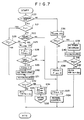
- Figure 7 shows another example of the operation of the control unit 10 after the engine has stalled.
- step S20 determines in step S20 whether the output of the L-terminal 86 is low. Since the engine has stalled, the answer in step S20 is YES and accordingly, the control unit 10 proceeds to step S21. In step S21, the control unit 10 determines whether an engine stall flag F is set to "1". If the engine has just stalled, the flag F should not have been set to "1", and accordingly, the answer in step S21 is NO. Then the control unit 10 proceeds to step S22. In step S22, the control unit 10 determines whether the output of the L-terminal 86 has been low for 0.5 seconds.
- step S22 If it is determined in step S22 that the output of the L-terminal 86 has been low for 0.5 seconds, the control unit 10 lights the warning lamp 88 in step S25, and sets the flag F to 1 and resets a delay control allowance flag FD to "0" in step S26. On the other hand, if it is determined in step S22 that the output of the L-terminal 86 has not been low for 0.5 seconds, the control unit 10 proceeds to step S23 and resets a convergence control flag FE (to be described later) to "0", though the flag FE has not been set to "1" yet. Thereafter, the control unit 10 carries out the normal type of control.
- a convergence control flag FE to be described later
- step S27 the control unit 10 determines in step S27 whether a predetermined time has lapsed since the engine stall flag F has been set to "1".
- the predetermined time may be suitably set taking into account various factors. For example, the predetermined time may be set to 10 to 15 seconds which is the time in which the driver may be expected to restart the engine.
- the control unit 10 proceeds to steps S23 and S24 and carries out the normal type of control. Then the control unit 10 continues to carry out the normal type of control until the predetermined time lapses (steps S20, S21, S28, S25, S26, S27, S23, S24.
- step S29 sets the convergence control flag FE to "1".
- the convergence control flag FE indicates that the convergence type of control is to be carried out.
- the target rear wheel turning angles ⁇ rTN to which the rear wheels are to be turned when the normal type of control is carried out are multiplied by a coefficient f(t) which gradually decreases from 1 to 0 as the time t lapses, and the values thus obtained are adopted as the target rear wheel turning angles ⁇ rTC.
- step S29 the control unit 10 starts the timer which counts the time t, the value from the timer being used in the calculation of the coefficient f(t) (steps S30 and S31).
- control unit 10 determines in step S32 whether the coefficient f(t) is zero. When it is determined that the coefficient f(t) is not zero, the control unit 10 proceeds to step S33 and carries out the convergence type of control, that is, controls the servomotor 4 with the target rear wheel turning angle ⁇ rTC being set at ⁇ rTN x f(t). Thereafter, the control unit 10 continues to perform the convergence type of control until the coefficient f(t) becomes zero (steps S20, S21, S28, S31, S32, S33). When the coefficient f(t) becomes zero, the control unit 10 finishes carrying out the convergence type of control. The control unit 10 resets the engine stall flag F and the convergence control flag FE and sets the delay control allowance flag FD (step S34), and then it makes an initial jump (step S35).
- control unit 10 When the driver restarts the engine after the engine stall flag F is set, the control unit 10 carries out the following type of control.
- step S36 the control unit 10 proceeds to step S36 and turns off the warning lamp 88. Then the control unit 10 determines in step S37 whether the convergence control flag FE has been set.
- step S37 If it is determined in step S37 that the convergence control flag FE has not been set, which means that the control unit 10 is carrying out the normal type of control, the control unit 10 proceeds to step S38.
- step S38 the control unit 10 sets the delay control allowance flag FD and sets the engine stall flag F. Thereafter, the control unit 10 proceeds to step S23 and continues to perform the normal type of control.
- step S37 If it is determined in step S37 that the convergence control flag FE has been set, the control unit 10 proceeds to step S39 and reverses the timer for the coefficient f(t). Then in step S40, the control unit 10 calculates the coefficient f(t) on the basis of the time t counted by the timer. Since the timer has been reversed, the value of t decreases as the time lapses, and accordingly, the value of the coefficient f(t) gradually increases to 1 as the time lapses. Further, the control unit 10 determines in step S41 whether the coefficient f(t) is 1. If it is determined that the coefficient f(t) is not 1, the control unit 10 proceeds to step S42 and carries out a returning type of control.
- control unit 10 controls the servomotor 4 with the target rear wheel turning angle ⁇ rTR during the performance of the returning type of control being set to be ⁇ rTN x f(t). Thereafter, the control unit 10 continues to perform the returning type of control until the coefficient f(t) becomes 1 (steps S20, S36, S37, S39 to S42). When the coefficient f(t) becomes 1 and execution of the returning type of control is completed, the control unit 10 proceeds to step S38 from step S41 and shifts to carrying out the normal type of control (steps S23 and S24). When the returning type of control is carried out before the control unit 10 shifts to carrying out the normal type of control, an abrupt change in the attitude of the vehicle can be prevented in cases where the engine is restarted during the carrying out of the convergence type of control.
- the normal type of control continues to be carried out for a predetermined time after the engine has stalled and then the type of control carried out is shifted to the convergence type.
- the control unit 10 stops controlling the servomotor 4. That is, when the performance of the convergence type of control is completed, the control unit 10 makes the vehicle behave as a two-wheel-steered vehicle and makes an initial jump. Thereafter, the control unit 10 does not control the servomotor 4 until the engine is restarted.
- Figure 8 shows the change of the coefficient f(t) during control by the control unit.
- the flow chart shown in Figure 7 may be modified in various ways. For example, when the front wheel turning angle becomes zero while the control unit 10 continues to carry out control after the engine has stalled (either the normal type of control or the convergence type of control), the control unit 10 may make the initial jump. Otherwise, the control unit 10 may carry out the convergence type of control as soon as the engine stalls.
- control means is arranged to continue controlling the electric motor until a predetermined condition is established after the engine has stalled.
- the predetermined condition may be set as desired. For example, a front wheel turning angle of zero, a predetermined lapse of time, the completion of the carrying out of the convergence type of control (completion of the convergence type of control may be regarded as occurring after a certain lapse of time if the time the coefficient f(t) takes to decrease to 0 from 1 is fixed), the turning off of the ignition switch, or the lowering of the voltage of the battery below a predetermined value (e.g., 8v) may be set as the predetermined condition.
- a front wheel turning angle of zero for example, a front wheel turning angle of zero, a predetermined lapse of time, the completion of the carrying out of the convergence type of control (completion of the convergence type of control may be regarded as occurring after a certain lapse of time if the time the coefficient f(t) takes to decrease to 0 from 1 is fixed), the turning off of the ignition switch, or the lowering of the voltage of the battery below a predetermined value (e.g., 8v)
- the type of control executed from when the engine stalls until the predetermined condition is established may be set as desired.
- the control means may be arranged so that it continues to carry out the normal type of control after the engine has stalled, or so that it shifts to carrying out the convergence type of control, or so that it holds the rear wheels at the turning angle they are set at when the engine stalls.
- the control means may be arranged so that it carries out two or more of such types of control according to the situation.
- control means be arranged so that it returns the rear wheels to the straight-ahead position and makes the vehicle behave as a two-wheel-steered vehicle before it ceases its control operations in the case where the rear wheels can be in a position other than the straight-ahead position upon establishment of the predetermined condition, e.g., when the control means is arranged so that it continues to perform the normal type of control after the engine has stalled, or so that it holds the rear wheels at the turning angle they are set at when the engine stalls.
- the normal type of control may continue to be carried out after a proper returning type of control has been carried out, if necessary.
- the rear wheel turning mechanism is driven by the output power of the servomotor, it may be driven by the output power of a hydraulic power cylinder which is provided with hydraulic pressure by a hydraulic pump driven by an electric motor which is energized by the battery.
Landscapes
- Engineering & Computer Science (AREA)
- Chemical & Material Sciences (AREA)
- Combustion & Propulsion (AREA)
- Transportation (AREA)
- Mechanical Engineering (AREA)
- Steering Control In Accordance With Driving Conditions (AREA)
- Steering-Linkage Mechanisms And Four-Wheel Steering (AREA)
Applications Claiming Priority (2)
| Application Number | Priority Date | Filing Date | Title |
|---|---|---|---|
| JP166384/88 | 1988-07-04 | ||
| JP63166384A JPH07468B2 (ja) | 1988-07-04 | 1988-07-04 | 車両の後輪操舵装置 |
Publications (3)
| Publication Number | Publication Date |
|---|---|
| EP0349992A2 EP0349992A2 (en) | 1990-01-10 |
| EP0349992A3 EP0349992A3 (en) | 1990-11-07 |
| EP0349992B1 true EP0349992B1 (en) | 1994-01-05 |
Family
ID=15830418
Family Applications (1)
| Application Number | Title | Priority Date | Filing Date |
|---|---|---|---|
| EP89112222A Expired - Lifetime EP0349992B1 (en) | 1988-07-04 | 1989-07-04 | Rear wheel turning system for a vehicle |
Country Status (4)
| Country | Link |
|---|---|
| US (1) | US4930592A (ja) |
| EP (1) | EP0349992B1 (ja) |
| JP (1) | JPH07468B2 (ja) |
| DE (1) | DE68912005T2 (ja) |
Families Citing this family (13)
| Publication number | Priority date | Publication date | Assignee | Title |
|---|---|---|---|---|
| JPH03112784A (ja) * | 1989-09-27 | 1991-05-14 | Mazda Motor Corp | 車両の後輪操舵装置 |
| EP0499027A3 (en) * | 1991-01-10 | 1993-03-17 | Nsk Ltd | Four-wheel steering apparatus |
| DE4101369A1 (de) * | 1991-01-18 | 1992-07-23 | Opel Adam Ag | Allradlenkung fuer ein kraftfahrzeug |
| JPH0577760A (ja) * | 1991-09-18 | 1993-03-30 | Honda Motor Co Ltd | 四輪操舵装置 |
| JPH0692248A (ja) * | 1991-12-17 | 1994-04-05 | Komatsu Forklift Co Ltd | 産業車両のステアリング装置 |
| US6082084A (en) * | 1995-11-13 | 2000-07-04 | Ransomes America Corporation | Electric riding mower with electric steering system |
| US7401677B2 (en) * | 2002-02-13 | 2008-07-22 | Trw Inc. | Self-centering steering system |
| US7392869B2 (en) * | 2005-11-01 | 2008-07-01 | Textron Inc. | Modular power source for riding mower |
| US7854293B2 (en) | 2007-02-20 | 2010-12-21 | Textron Innovations Inc. | Steering operated by linear electric device |
| US8521384B2 (en) * | 2008-01-28 | 2013-08-27 | Textron Innovations Inc. | Turf maintenance vehicle all-wheel drive system |
| JP4924757B2 (ja) * | 2009-05-08 | 2012-04-25 | トヨタ自動車株式会社 | 車両駆動制御装置 |
| DE102012008782B4 (de) * | 2012-04-28 | 2017-06-22 | Audi Ag | Verfahren zum Betreiben eines mit einer lenkbaren Vorderachse und einer lenkbaren Hinterachse ausgestatteten Kraftfahrzeugs |
| GB2618548A (en) * | 2022-05-09 | 2023-11-15 | Jaguar Land Rover Ltd | Vehicle controller and control method |
Family Cites Families (10)
| Publication number | Priority date | Publication date | Assignee | Title |
|---|---|---|---|---|
| US4532567A (en) * | 1983-02-18 | 1985-07-30 | General Motors Corporation | Electric power steering stall protection circuit |
| JPH069977B2 (ja) * | 1984-02-22 | 1994-02-09 | 日産自動車株式会社 | 車両の後輪操舵方法 |
| JPS61202977A (ja) * | 1985-03-06 | 1986-09-08 | Jidosha Kiki Co Ltd | 車両の操舵装置 |
| JPH0637175B2 (ja) * | 1985-08-13 | 1994-05-18 | マツダ株式会社 | 車両の4輪操舵装置 |
| JPS62122827A (ja) * | 1985-11-22 | 1987-06-04 | Isuzu Motors Ltd | 電子制御装置における電源制御装置 |
| JPS62137277A (ja) * | 1985-12-10 | 1987-06-20 | Mazda Motor Corp | 車両の4輪操舵装置 |
| JPH0723104B2 (ja) * | 1986-04-22 | 1995-03-15 | 三菱電機株式会社 | モ−タ駆動式パワ−ステアリング制御装置 |
| US4751978A (en) * | 1987-03-16 | 1988-06-21 | Trw Inc. | Electric assist steering system with alternator power source |
| JPS63273038A (ja) * | 1987-05-01 | 1988-11-10 | Mazda Motor Corp | 車載制御機器の電源異常検出装置 |
| JP2824838B2 (ja) * | 1987-12-10 | 1998-11-18 | スズキ株式会社 | 自動車の四輪操舵装置 |
-
1988
- 1988-07-04 JP JP63166384A patent/JPH07468B2/ja not_active Expired - Fee Related
-
1989
- 1989-07-03 US US07/374,695 patent/US4930592A/en not_active Expired - Fee Related
- 1989-07-04 DE DE89112222T patent/DE68912005T2/de not_active Expired - Fee Related
- 1989-07-04 EP EP89112222A patent/EP0349992B1/en not_active Expired - Lifetime
Also Published As
| Publication number | Publication date |
|---|---|
| EP0349992A2 (en) | 1990-01-10 |
| US4930592A (en) | 1990-06-05 |
| JPH07468B2 (ja) | 1995-01-11 |
| JPH0218173A (ja) | 1990-01-22 |
| DE68912005D1 (de) | 1994-02-17 |
| EP0349992A3 (en) | 1990-11-07 |
| DE68912005T2 (de) | 1994-04-28 |
Similar Documents
| Publication | Publication Date | Title |
|---|---|---|
| EP0349992B1 (en) | Rear wheel turning system for a vehicle | |
| EP0316932B1 (en) | Rear wheel steering apparatus for automobile | |
| JP2685205B2 (ja) | 車両の後輪操舵装置 | |
| JP2679803B2 (ja) | 車両の後輪操舵装置 | |
| JPH01153383A (ja) | 自動車の四輪操舵装置 | |
| US4976328A (en) | Rear wheel turning system | |
| JP2578975B2 (ja) | 車両動特性制御装置 | |
| US5007494A (en) | Rear wheel turning system | |
| JP2552357B2 (ja) | 車両動特性制御装置 | |
| JPH06278639A (ja) | 車両の制御装置 | |
| JP2758166B2 (ja) | 車両の後輪操舵装置 | |
| JPH0358948B2 (ja) | ||
| JP3041495B2 (ja) | 四輪操舵装置 | |
| JP2679799B2 (ja) | 車両の後輪操舵装置 | |
| JP2680636B2 (ja) | 車両の後輪操舵装置 | |
| JP2825835B2 (ja) | 車両の後輪操舵装置 | |
| JPH0358947B2 (ja) | ||
| JP2686956B2 (ja) | 車両の後輪操舵装置 | |
| JPH01145275A (ja) | 車両の後輪操舵装置 | |
| JPH07315241A (ja) | 自動操舵装置の制御装置 | |
| JP2528455B2 (ja) | 車両の4輪操舵装置 | |
| JP2607562B2 (ja) | 車両の後輪操舵装置 | |
| JPH01145277A (ja) | 車両の後輪操舵装置 | |
| JPH01148667A (ja) | 車両の後輪操舵装置 | |
| JPH01148668A (ja) | 車両の後輪操舵装置 |
Legal Events
| Date | Code | Title | Description |
|---|---|---|---|
| PUAI | Public reference made under article 153(3) epc to a published international application that has entered the european phase |
Free format text: ORIGINAL CODE: 0009012 |
|
| AK | Designated contracting states |
Kind code of ref document: A2 Designated state(s): DE FR GB |
|
| PUAL | Search report despatched |
Free format text: ORIGINAL CODE: 0009013 |
|
| AK | Designated contracting states |
Kind code of ref document: A3 Designated state(s): DE FR GB |
|
| 17P | Request for examination filed |
Effective date: 19901227 |
|
| 17Q | First examination report despatched |
Effective date: 19920817 |
|
| GRAA | (expected) grant |
Free format text: ORIGINAL CODE: 0009210 |
|
| AK | Designated contracting states |
Kind code of ref document: B1 Designated state(s): DE FR GB |
|
| REF | Corresponds to: |
Ref document number: 68912005 Country of ref document: DE Date of ref document: 19940217 |
|
| ET | Fr: translation filed | ||
| PLBE | No opposition filed within time limit |
Free format text: ORIGINAL CODE: 0009261 |
|
| STAA | Information on the status of an ep patent application or granted ep patent |
Free format text: STATUS: NO OPPOSITION FILED WITHIN TIME LIMIT |
|
| 26N | No opposition filed | ||
| PGFP | Annual fee paid to national office [announced via postgrant information from national office to epo] |
Ref country code: GB Payment date: 19960625 Year of fee payment: 8 |
|
| PGFP | Annual fee paid to national office [announced via postgrant information from national office to epo] |
Ref country code: FR Payment date: 19960709 Year of fee payment: 8 |
|
| PGFP | Annual fee paid to national office [announced via postgrant information from national office to epo] |
Ref country code: DE Payment date: 19960712 Year of fee payment: 8 |
|
| PG25 | Lapsed in a contracting state [announced via postgrant information from national office to epo] |
Ref country code: GB Free format text: LAPSE BECAUSE OF NON-PAYMENT OF DUE FEES Effective date: 19970704 |
|
| GBPC | Gb: european patent ceased through non-payment of renewal fee |
Effective date: 19970704 |
|
| PG25 | Lapsed in a contracting state [announced via postgrant information from national office to epo] |
Ref country code: FR Free format text: LAPSE BECAUSE OF NON-PAYMENT OF DUE FEES Effective date: 19980331 |
|
| PG25 | Lapsed in a contracting state [announced via postgrant information from national office to epo] |
Ref country code: DE Free format text: LAPSE BECAUSE OF NON-PAYMENT OF DUE FEES Effective date: 19980401 |
|
| REG | Reference to a national code |
Ref country code: FR Ref legal event code: ST |