EP0349700B1 - Gabarit pour faire des encoches dans des sangles - Google Patents
Gabarit pour faire des encoches dans des sangles Download PDFInfo
- Publication number
- EP0349700B1 EP0349700B1 EP88890277A EP88890277A EP0349700B1 EP 0349700 B1 EP0349700 B1 EP 0349700B1 EP 88890277 A EP88890277 A EP 88890277A EP 88890277 A EP88890277 A EP 88890277A EP 0349700 B1 EP0349700 B1 EP 0349700B1
- Authority
- EP
- European Patent Office
- Prior art keywords
- template
- disc
- watch
- template according
- depressions
- Prior art date
- Legal status (The legal status is an assumption and is not a legal conclusion. Google has not performed a legal analysis and makes no representation as to the accuracy of the status listed.)
- Expired - Lifetime
Links
- 238000004080 punching Methods 0.000 claims description 6
- 238000004519 manufacturing process Methods 0.000 claims 2
- 238000007373 indentation Methods 0.000 abstract 3
- 239000000853 adhesive Substances 0.000 description 3
- 230000001070 adhesive effect Effects 0.000 description 3
- 239000010985 leather Substances 0.000 description 2
- 238000000034 method Methods 0.000 description 2
- 239000002184 metal Substances 0.000 description 1
Images

Classifications
-
- B—PERFORMING OPERATIONS; TRANSPORTING
- B23—MACHINE TOOLS; METAL-WORKING NOT OTHERWISE PROVIDED FOR
- B23D—PLANING; SLOTTING; SHEARING; BROACHING; SAWING; FILING; SCRAPING; LIKE OPERATIONS FOR WORKING METAL BY REMOVING MATERIAL, NOT OTHERWISE PROVIDED FOR
- B23D51/00—Sawing machines or sawing devices working with straight blades, characterised only by constructional features of particular parts; Carrying or attaching means for tools, covered by this subclass, which are connected to a carrier at both ends
- B23D51/08—Sawing machines or sawing devices working with straight blades, characterised only by constructional features of particular parts; Carrying or attaching means for tools, covered by this subclass, which are connected to a carrier at both ends of devices for mounting straight saw blades or other tools
- B23D51/10—Sawing machines or sawing devices working with straight blades, characterised only by constructional features of particular parts; Carrying or attaching means for tools, covered by this subclass, which are connected to a carrier at both ends of devices for mounting straight saw blades or other tools for hand-held or hand-operated devices
-
- B—PERFORMING OPERATIONS; TRANSPORTING
- B26—HAND CUTTING TOOLS; CUTTING; SEVERING
- B26B—HAND-HELD CUTTING TOOLS NOT OTHERWISE PROVIDED FOR
- B26B29/00—Guards or sheaths or guides for hand cutting tools; Arrangements for guiding hand cutting tools
- B26B29/06—Arrangements for guiding hand cutting tools
-
- B—PERFORMING OPERATIONS; TRANSPORTING
- B26—HAND CUTTING TOOLS; CUTTING; SEVERING
- B26D—CUTTING; DETAILS COMMON TO MACHINES FOR PERFORATING, PUNCHING, CUTTING-OUT, STAMPING-OUT OR SEVERING
- B26D7/00—Details of apparatus for cutting, cutting-out, stamping-out, punching, perforating, or severing by means other than cutting
- B26D7/01—Means for holding or positioning work
- B26D7/015—Means for holding or positioning work for sheet material or piles of sheets
Definitions
- the invention relates to a template for producing one or more cutouts in straps and to be fastened to a watch, in particular in ends of watch bands bent into loops.
- watch straps It is known to bend watch straps at their end to be attached to the housing of a watch into a loop in which a web to be connected to the watch lugs, e.g. a spring pin is included.
- Such watch straps are known from AT-PS 252 634. It is also known to form eyelets on watch bands, e.g. in a plastic part of the watch strap, via which the watch straps can be connected to the housing of a watch (cf. EP-A-97 638 and 199 708).
- Watch cases are also known, on which projections are provided which engage in slots in the end of watch straps to be fastened to the watch case. These watch cases usually also have lugs on the side of the watch strap. Such hinge-like connections between the watch band and the watch case are provided, for example, in the watches known as "swatch watches”.
- the invention has for its object to provide a template of the type mentioned, with the necessary for the hinge-like connection between the strap (watch strap) and a component (watch case) can be generated in the end of the watch strap to be attached to the watch.
- any watch straps made of leather or combinations of leather and plastic or pure plastic straps which may all consist of several layers, can be attached to watches by means of a hinge-like connection.
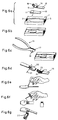
- the template 1 shown in Fig. 1 is a substantially rectangular plate made of metal or plastic, which has three recesses 2, 3 and 4 for receiving the cut-out end of a watch band or other strap.
- Two slots 5 are provided in the area of the depression 2 and two further slots 6 are provided at the edge of the depression 2.
- the webs 7 arranged between the slots 5 and 6 have at their free ends upward-facing stops 8 for the front end of the watch band to be provided with cutouts.
- Slits 5 and 6 are also provided in the region of the two other depressions 3 and 4.
- the slots 6 are aligned in the region of the longitudinal side edges of the watch band to be provided with cutouts, so that the side edges are cut during the punching process in the region of the slots 6 so that two essentially surfaces extending in the longitudinal direction of the watch band are formed which fit between the two outer projections of a hinge-joint-like arrangement on a watch case.
- FIGS. 6a to 6g The use of the template 1 shown in FIGS. 1 to 5 for fastening a watch band 10, which has an end 12 to be bent into a loop 11, is described below with reference to FIGS. 6a to 6g (cf. FIG. 6a ).
- the end 12 of the watch band 10 is inserted into the recess 2 of the template 1 with the end folded down.
- the punching tool 13 shown in FIG. 6c As indicated in FIG.
- the adhesive in the areas 18 and 19 of the watch band 10 (FIG. 6a) is activated and the loop 11 is closed and fixed with the help of a clamp 22 until the adhesive connection is completed.
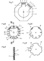
- the template 30 shown in FIG. 7 is octagonal and has two recesses 31, 32 of different widths, the slots 5 and 6 also being arranged differently in the region of these recesses 31, 32.
- the use of the template 30 corresponds to the use of the template 1, as has been explained with reference to FIGS. 6a to 6g.
- the template 40 shown in FIGS. 8 to 10 is also octagonal and consists of three disks 41, 42 and 43.
- the disk 41 of the template 40 are initially depressions 31 and 32, which are similar to the depressions 31, 32 of the template 30 are provided.
- each recess 50 In the disk 41 of the template 40, six further depressions 50 are provided, which can be of different widths and start from a depression provided centrally in the disk 41.
- cutouts 51 are provided in the disk 41.
- stops 44 At the edge end of each recess 50 stops 44 are provided for the radial alignment of the end 12 of the watch band 10 to be provided with cutouts.
- the cutouts 51 can have different widths, as is indicated in FIG. 8.
- the disk 42 is rotatably connected to the disk 41 and has slots in the regions 45 and 46 which correspond to the slots 5 and 6 of the depressions 31 and 32. Furthermore, recesses 47 are provided in the disk 42, all of which have the same radial dimension x, but are of different widths.
- the disk 43 has a recess 48, which is brought into the area of the depressions 31 and 32 or the slots 5 and 6 provided there by turning the disk 43 relative to the disk 41, if cutouts 31 and 32 in FIG Watchbands are to be generated.
- the three disks 41, 42 and 43 of the template 40 can be rotated relative to one another, but with latching means e.g. in recesses, not shown, in the disks engaging projections which secure the disks when the three disks 41, 42, 43 of the template 40 are, for example, in the rotational position shown in FIG. 8.
- latching means e.g. in recesses, not shown, in the disks engaging projections which secure the disks when the three disks 41, 42, 43 of the template 40 are, for example, in the rotational position shown in FIG. 8.
- the disks are secured against rotation against one another if any of the recesses 47 are aligned with any of the recesses 49 and these are both aligned with any of the recesses 51 of the disk 41.
- the use of the template 40 corresponds with respect to its recesses 31 and 32 to the template 30 and 1, respectively.
- the cutouts 51 and the cutouts 47 and 49 serve to produce cutouts of different widths and / or different depths in the ends 12 of watch bands 10.
- the punching tool 13 shown in FIG. 6c can be used by actuating it several times, the area in which the punching tool can be used passing through both in width (transverse to the band) and in depth (in the band direction) the combination of one of the recesses 51 with one of the recesses 47 and 49 is defined.
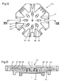
- the template 52 shown in FIGS. 12 and 13 is a modified embodiment of the template 40 shown in FIGS. 8 to 11.
- the template 52 also consists of disks 41, 42 and 43.
- a rotary handle part 53 which protrudes through the disc 43, connected to the disc 42, for example pressed into it.
- a rotary handle part 54 is connected to the disk 43 in a manner similar to the rotary handle part 53 with the disk 42.
- the disk 43 is rotatably mounted on the rotary handle part 53 via the rotary handle part 54 and this on the disk 41 via the disk 42.
- Slits 55 are provided in the disk 41 and holes 56 in the disk 42, which lie one above the other in each use position of the template 52.
- the number of slots 55 and holes 56 corresponds to the number of depressions 31, 32 and 50, respectively.
- Codings corresponding to the depressions 31, 32 and 50 are provided on the disk 41 in the area of the slots 55 on the surface 57.
Landscapes
- Engineering & Computer Science (AREA)
- Mechanical Engineering (AREA)
- Life Sciences & Earth Sciences (AREA)
- Forests & Forestry (AREA)
- Adornments (AREA)
- Electric Clocks (AREA)
- Buckles (AREA)
- Processing Of Stones Or Stones Resemblance Materials (AREA)
- Crystals, And After-Treatments Of Crystals (AREA)
Claims (12)
Priority Applications (1)
| Application Number | Priority Date | Filing Date | Title |
|---|---|---|---|
| AT88890277T ATE75587T1 (de) | 1988-07-04 | 1988-11-07 | Schablone zum erzeugen von ausschnitten in riemen. |
Applications Claiming Priority (2)
| Application Number | Priority Date | Filing Date | Title |
|---|---|---|---|
| DE8808558U DE8808558U1 (de) | 1988-07-04 | 1988-07-04 | Schablone zum Erzeugen von Ausschnitten in Riemen |
| DE8808558U | 1988-07-04 |
Publications (3)
| Publication Number | Publication Date |
|---|---|
| EP0349700A2 EP0349700A2 (fr) | 1990-01-10 |
| EP0349700A3 EP0349700A3 (en) | 1990-06-27 |
| EP0349700B1 true EP0349700B1 (fr) | 1992-05-06 |
Family
ID=6825633
Family Applications (1)
| Application Number | Title | Priority Date | Filing Date |
|---|---|---|---|
| EP88890277A Expired - Lifetime EP0349700B1 (fr) | 1988-07-04 | 1988-11-07 | Gabarit pour faire des encoches dans des sangles |
Country Status (5)
| Country | Link |
|---|---|
| US (1) | US4936019A (fr) |
| EP (1) | EP0349700B1 (fr) |
| JP (1) | JPH0231702A (fr) |
| AT (1) | ATE75587T1 (fr) |
| DE (2) | DE8808558U1 (fr) |
Families Citing this family (6)
| Publication number | Priority date | Publication date | Assignee | Title |
|---|---|---|---|---|
| US5229595A (en) * | 1991-12-19 | 1993-07-20 | Xerox Corporation | Fluid-filled color filtered input scanner arrays |
| US5363351A (en) * | 1993-06-29 | 1994-11-08 | Chisco, Inc. | Watchband adaptor fitting for a wristwatch casing |
| US6637121B2 (en) * | 2002-01-07 | 2003-10-28 | Byron G. Barefoot | Internal weld profile gauge |
| US6981332B2 (en) * | 2002-01-07 | 2006-01-03 | Barefoot Byron G | Internal weld profile gauge |
| US6594914B1 (en) * | 2002-02-12 | 2003-07-22 | Kevin Babcock | Ice skate blade squaring gauge |
| USD1070614S1 (en) * | 2022-06-13 | 2025-04-15 | Leslie Anthony | Strap template device |
Family Cites Families (5)
| Publication number | Priority date | Publication date | Assignee | Title |
|---|---|---|---|---|
| US2619270A (en) * | 1949-09-06 | 1952-11-25 | Foster John | Wrist watch support |
| AT252634B (de) * | 1965-07-14 | 1967-02-27 | Hans Hirsch U Soehne Leder Und | Uhrarmband aus Leder od. dgl. |
| AT380159B (de) * | 1982-06-17 | 1986-04-25 | Hirsch Hermann Leder Kunstst | Riemen |
| CH653316A5 (en) * | 1983-04-16 | 1985-12-31 | Bracelets Union G Rais Et Fils | Method for manufacturing a turned-in keeper, turned-in keeper thus obtained and use for a watch strap |
| AT398026B (de) * | 1985-04-15 | 1994-08-25 | Hirsch Armbaender | Verfahren zur herstellung wenigstens zweilagiger gegenstände |
-
1988
- 1988-07-04 DE DE8808558U patent/DE8808558U1/de not_active Expired
- 1988-11-07 AT AT88890277T patent/ATE75587T1/de not_active IP Right Cessation
- 1988-11-07 EP EP88890277A patent/EP0349700B1/fr not_active Expired - Lifetime
- 1988-11-07 DE DE8888890277T patent/DE3870873D1/de not_active Expired - Fee Related
- 1988-12-09 US US07/282,253 patent/US4936019A/en not_active Expired - Fee Related
- 1988-12-22 JP JP63324740A patent/JPH0231702A/ja active Pending
Also Published As
| Publication number | Publication date |
|---|---|
| DE8808558U1 (de) | 1988-08-18 |
| US4936019A (en) | 1990-06-26 |
| EP0349700A3 (en) | 1990-06-27 |
| JPH0231702A (ja) | 1990-02-01 |
| ATE75587T1 (de) | 1992-05-15 |
| DE3870873D1 (de) | 1992-06-11 |
| EP0349700A2 (fr) | 1990-01-10 |
Similar Documents
| Publication | Publication Date | Title |
|---|---|---|
| DE2261606C3 (de) | Klebebefestigung für Blattmaterial | |
| DE2211511A1 (de) | Magazinstreifen fuer ein geraet zum eintreiben von ziernaegeln | |
| DE2049514B2 (de) | Mehrklingen-Rasiergerät | |
| EP0349700B1 (fr) | Gabarit pour faire des encoches dans des sangles | |
| DE1786579C3 (de) | Lochkarte | |
| DE69410290T2 (de) | Spender für blätter oder streifen | |
| DE60201715T2 (de) | Zwischenstück mit abziehbaren Folien von identifizierbarer Dicke | |
| DE20206514U1 (de) | Karte, insbesondere Schmuckkarte | |
| DE2656021C3 (de) | Briefordner zur Aufnahme von gelochtem Schriftgut | |
| DE2439084C2 (de) | Bindeelement für ein Buch | |
| DE2720466C2 (fr) | ||
| DE29811093U1 (de) | Haarschere | |
| DE9310598U1 (de) | Motivkarte | |
| DE69500292T2 (de) | Kontaktdruckknopfschalter | |
| DE2332291C3 (de) | Zeichenvorrichtung | |
| DE2933049C2 (de) | Symbolbausatz | |
| DE2454579C3 (de) | Anzeigevorrichtung für die Parkerlaubnis von Fahrzeugen | |
| DE1102543B (de) | Verfahren zum Heften und Heftung von uebereinandergelegten Schreibpapierbahnen, insbesondere fuer Endlossaetze | |
| DE3345131A1 (de) | Gliederband, insbesondere schmuck- oder uhrarmband, und verfahren zu seiner herstellung | |
| DE2504408C3 (de) | Weckerauslösung | |
| EP0638441A1 (fr) | Dispositif pour relier de façon amovible des cartes de visite avec des cartes d'un fichier | |
| WO1984000674A1 (fr) | Element de bracelet de montre avec donnees de calendrier | |
| DE7729056U1 (de) | Tuerklinken-rueckhol- bzw. rueckstellvorrichtung | |
| EP0212347A1 (fr) | Perforateur pour lettres | |
| DE2543263C2 (de) | Drucktaste, insbesondere für Schlösser von Sicherheitsgurten |
Legal Events
| Date | Code | Title | Description |
|---|---|---|---|
| PUAI | Public reference made under article 153(3) epc to a published international application that has entered the european phase |
Free format text: ORIGINAL CODE: 0009012 |
|
| AK | Designated contracting states |
Kind code of ref document: A2 Designated state(s): AT BE CH DE ES FR GB LI LU NL |
|
| PUAL | Search report despatched |
Free format text: ORIGINAL CODE: 0009013 |
|
| AK | Designated contracting states |
Kind code of ref document: A3 Designated state(s): AT BE CH DE ES FR GB LI LU NL |
|
| 17P | Request for examination filed |
Effective date: 19900528 |
|
| GRAA | (expected) grant |
Free format text: ORIGINAL CODE: 0009210 |
|
| AK | Designated contracting states |
Kind code of ref document: B1 Designated state(s): AT BE CH DE ES FR GB LI LU NL |
|
| PG25 | Lapsed in a contracting state [announced via postgrant information from national office to epo] |
Ref country code: NL Effective date: 19920506 Ref country code: GB Effective date: 19920506 Ref country code: FR Effective date: 19920506 Ref country code: ES Free format text: THE PATENT HAS BEEN ANNULLED BY A DECISION OF A NATIONAL AUTHORITY Effective date: 19920506 Ref country code: BE Effective date: 19920506 |
|
| REF | Corresponds to: |
Ref document number: 75587 Country of ref document: AT Date of ref document: 19920515 Kind code of ref document: T |
|
| REF | Corresponds to: |
Ref document number: 3870873 Country of ref document: DE Date of ref document: 19920611 |
|
| EN | Fr: translation not filed | ||
| NLV1 | Nl: lapsed or annulled due to failure to fulfill the requirements of art. 29p and 29m of the patents act | ||
| PG25 | Lapsed in a contracting state [announced via postgrant information from national office to epo] |
Ref country code: AT Effective date: 19921107 |
|
| GBV | Gb: ep patent (uk) treated as always having been void in accordance with gb section 77(7)/1977 [no translation filed] | ||
| PG25 | Lapsed in a contracting state [announced via postgrant information from national office to epo] |
Ref country code: LU Free format text: LAPSE BECAUSE OF NON-PAYMENT OF DUE FEES Effective date: 19921130 Ref country code: LI Effective date: 19921130 Ref country code: CH Effective date: 19921130 |
|
| PLBE | No opposition filed within time limit |
Free format text: ORIGINAL CODE: 0009261 |
|
| STAA | Information on the status of an ep patent application or granted ep patent |
Free format text: STATUS: NO OPPOSITION FILED WITHIN TIME LIMIT |
|
| 26N | No opposition filed | ||
| REG | Reference to a national code |
Ref country code: CH Ref legal event code: PL |
|
| PG25 | Lapsed in a contracting state [announced via postgrant information from national office to epo] |
Ref country code: DE Effective date: 19930803 |