EP0349700B1 - Templet for making notches in straps - Google Patents
Templet for making notches in straps Download PDFInfo
- Publication number
- EP0349700B1 EP0349700B1 EP88890277A EP88890277A EP0349700B1 EP 0349700 B1 EP0349700 B1 EP 0349700B1 EP 88890277 A EP88890277 A EP 88890277A EP 88890277 A EP88890277 A EP 88890277A EP 0349700 B1 EP0349700 B1 EP 0349700B1
- Authority
- EP
- European Patent Office
- Prior art keywords
- template
- disc
- watch
- template according
- depressions
- Prior art date
- Legal status (The legal status is an assumption and is not a legal conclusion. Google has not performed a legal analysis and makes no representation as to the accuracy of the status listed.)
- Expired - Lifetime
Links
Images

Classifications
-
- B—PERFORMING OPERATIONS; TRANSPORTING
- B23—MACHINE TOOLS; METAL-WORKING NOT OTHERWISE PROVIDED FOR
- B23D—PLANING; SLOTTING; SHEARING; BROACHING; SAWING; FILING; SCRAPING; LIKE OPERATIONS FOR WORKING METAL BY REMOVING MATERIAL, NOT OTHERWISE PROVIDED FOR
- B23D51/00—Sawing machines or sawing devices working with straight blades, characterised only by constructional features of particular parts; Carrying or attaching means for tools, covered by this subclass, which are connected to a carrier at both ends
- B23D51/08—Sawing machines or sawing devices working with straight blades, characterised only by constructional features of particular parts; Carrying or attaching means for tools, covered by this subclass, which are connected to a carrier at both ends of devices for mounting straight saw blades or other tools
- B23D51/10—Sawing machines or sawing devices working with straight blades, characterised only by constructional features of particular parts; Carrying or attaching means for tools, covered by this subclass, which are connected to a carrier at both ends of devices for mounting straight saw blades or other tools for hand-held or hand-operated devices
-
- B—PERFORMING OPERATIONS; TRANSPORTING
- B26—HAND CUTTING TOOLS; CUTTING; SEVERING
- B26B—HAND-HELD CUTTING TOOLS NOT OTHERWISE PROVIDED FOR
- B26B29/00—Guards or sheaths or guides for hand cutting tools; Arrangements for guiding hand cutting tools
- B26B29/06—Arrangements for guiding hand cutting tools
-
- B—PERFORMING OPERATIONS; TRANSPORTING
- B26—HAND CUTTING TOOLS; CUTTING; SEVERING
- B26D—CUTTING; DETAILS COMMON TO MACHINES FOR PERFORATING, PUNCHING, CUTTING-OUT, STAMPING-OUT OR SEVERING
- B26D7/00—Details of apparatus for cutting, cutting-out, stamping-out, punching, perforating, or severing by means other than cutting
- B26D7/01—Means for holding or positioning work
- B26D7/015—Means for holding or positioning work for sheet material or piles of sheets
Definitions
- the invention relates to a template for producing one or more cutouts in straps and to be fastened to a watch, in particular in ends of watch bands bent into loops.
- watch straps It is known to bend watch straps at their end to be attached to the housing of a watch into a loop in which a web to be connected to the watch lugs, e.g. a spring pin is included.
- Such watch straps are known from AT-PS 252 634. It is also known to form eyelets on watch bands, e.g. in a plastic part of the watch strap, via which the watch straps can be connected to the housing of a watch (cf. EP-A-97 638 and 199 708).
- Watch cases are also known, on which projections are provided which engage in slots in the end of watch straps to be fastened to the watch case. These watch cases usually also have lugs on the side of the watch strap. Such hinge-like connections between the watch band and the watch case are provided, for example, in the watches known as "swatch watches”.
- the invention has for its object to provide a template of the type mentioned, with the necessary for the hinge-like connection between the strap (watch strap) and a component (watch case) can be generated in the end of the watch strap to be attached to the watch.
- any watch straps made of leather or combinations of leather and plastic or pure plastic straps which may all consist of several layers, can be attached to watches by means of a hinge-like connection.
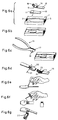
- the template 1 shown in Fig. 1 is a substantially rectangular plate made of metal or plastic, which has three recesses 2, 3 and 4 for receiving the cut-out end of a watch band or other strap.
- Two slots 5 are provided in the area of the depression 2 and two further slots 6 are provided at the edge of the depression 2.
- the webs 7 arranged between the slots 5 and 6 have at their free ends upward-facing stops 8 for the front end of the watch band to be provided with cutouts.
- Slits 5 and 6 are also provided in the region of the two other depressions 3 and 4.
- the slots 6 are aligned in the region of the longitudinal side edges of the watch band to be provided with cutouts, so that the side edges are cut during the punching process in the region of the slots 6 so that two essentially surfaces extending in the longitudinal direction of the watch band are formed which fit between the two outer projections of a hinge-joint-like arrangement on a watch case.
- FIGS. 6a to 6g The use of the template 1 shown in FIGS. 1 to 5 for fastening a watch band 10, which has an end 12 to be bent into a loop 11, is described below with reference to FIGS. 6a to 6g (cf. FIG. 6a ).
- the end 12 of the watch band 10 is inserted into the recess 2 of the template 1 with the end folded down.
- the punching tool 13 shown in FIG. 6c As indicated in FIG.
- the adhesive in the areas 18 and 19 of the watch band 10 (FIG. 6a) is activated and the loop 11 is closed and fixed with the help of a clamp 22 until the adhesive connection is completed.
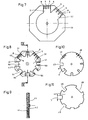
- the template 30 shown in FIG. 7 is octagonal and has two recesses 31, 32 of different widths, the slots 5 and 6 also being arranged differently in the region of these recesses 31, 32.
- the use of the template 30 corresponds to the use of the template 1, as has been explained with reference to FIGS. 6a to 6g.
- the template 40 shown in FIGS. 8 to 10 is also octagonal and consists of three disks 41, 42 and 43.
- the disk 41 of the template 40 are initially depressions 31 and 32, which are similar to the depressions 31, 32 of the template 30 are provided.
- each recess 50 In the disk 41 of the template 40, six further depressions 50 are provided, which can be of different widths and start from a depression provided centrally in the disk 41.
- cutouts 51 are provided in the disk 41.
- stops 44 At the edge end of each recess 50 stops 44 are provided for the radial alignment of the end 12 of the watch band 10 to be provided with cutouts.
- the cutouts 51 can have different widths, as is indicated in FIG. 8.
- the disk 42 is rotatably connected to the disk 41 and has slots in the regions 45 and 46 which correspond to the slots 5 and 6 of the depressions 31 and 32. Furthermore, recesses 47 are provided in the disk 42, all of which have the same radial dimension x, but are of different widths.
- the disk 43 has a recess 48, which is brought into the area of the depressions 31 and 32 or the slots 5 and 6 provided there by turning the disk 43 relative to the disk 41, if cutouts 31 and 32 in FIG Watchbands are to be generated.
- the three disks 41, 42 and 43 of the template 40 can be rotated relative to one another, but with latching means e.g. in recesses, not shown, in the disks engaging projections which secure the disks when the three disks 41, 42, 43 of the template 40 are, for example, in the rotational position shown in FIG. 8.
- latching means e.g. in recesses, not shown, in the disks engaging projections which secure the disks when the three disks 41, 42, 43 of the template 40 are, for example, in the rotational position shown in FIG. 8.
- the disks are secured against rotation against one another if any of the recesses 47 are aligned with any of the recesses 49 and these are both aligned with any of the recesses 51 of the disk 41.
- the use of the template 40 corresponds with respect to its recesses 31 and 32 to the template 30 and 1, respectively.
- the cutouts 51 and the cutouts 47 and 49 serve to produce cutouts of different widths and / or different depths in the ends 12 of watch bands 10.
- the punching tool 13 shown in FIG. 6c can be used by actuating it several times, the area in which the punching tool can be used passing through both in width (transverse to the band) and in depth (in the band direction) the combination of one of the recesses 51 with one of the recesses 47 and 49 is defined.
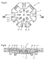
- the template 52 shown in FIGS. 12 and 13 is a modified embodiment of the template 40 shown in FIGS. 8 to 11.
- the template 52 also consists of disks 41, 42 and 43.
- a rotary handle part 53 which protrudes through the disc 43, connected to the disc 42, for example pressed into it.
- a rotary handle part 54 is connected to the disk 43 in a manner similar to the rotary handle part 53 with the disk 42.
- the disk 43 is rotatably mounted on the rotary handle part 53 via the rotary handle part 54 and this on the disk 41 via the disk 42.
- Slits 55 are provided in the disk 41 and holes 56 in the disk 42, which lie one above the other in each use position of the template 52.
- the number of slots 55 and holes 56 corresponds to the number of depressions 31, 32 and 50, respectively.
- Codings corresponding to the depressions 31, 32 and 50 are provided on the disk 41 in the area of the slots 55 on the surface 57.
Abstract
Description
Die Erfindung betrifft eine Schablone zum Erzeugen von einem oder mehreren Ausschnitten in Riemen und am einer Uhr zu befestigenden, insbesondere in zu Schlaufen gebogenen Enden von Uhrbändern.The invention relates to a template for producing one or more cutouts in straps and to be fastened to a watch, in particular in ends of watch bands bent into loops.
Es ist bekannt, Uhrbänder an ihrem am Gehäuse einer Uhr zu befestigenden Ende zu einer Schlaufe umzubiegen, in der ein mit den Uhranstößen zu verbindender Steg, z.B. ein Federstift, aufgenommen ist. Derartige Uhrbänder sind aus der AT-PS 252 634 bekannt. Es ist auch bekannt, an Uhrbändern Ösen auszubilden, z.B. in einem Kunststoffteil des Uhrbandes, über welche die Uhrbänder mit dem Gehäuse einer Uhr verbunden werden können (vgl. EP-A-97 638 und 199 708).It is known to bend watch straps at their end to be attached to the housing of a watch into a loop in which a web to be connected to the watch lugs, e.g. a spring pin is included. Such watch straps are known from AT-PS 252 634. It is also known to form eyelets on watch bands, e.g. in a plastic part of the watch strap, via which the watch straps can be connected to the housing of a watch (cf. EP-A-97 638 and 199 708).
Es sind auch Uhrgehäuse bekannt, an welchen Vorsprünge vorgesehen sind, die in Schlitze in den am Uhrgehäuse zu befestigenden Ende von Uhrbändern eingreifen. Diese Uhrgehäuse besitzen für gewöhnlich auch seitlich am Ende des Uhrbandes anliegende Anstöße. Derartige scharniergelenkartige Verbindungen zwischen Uhrband und Uhrgehäuse sind beispielsweise bei den als "swatch-Uhren" bekannten Uhren vorgesehen.Watch cases are also known, on which projections are provided which engage in slots in the end of watch straps to be fastened to the watch case. These watch cases usually also have lugs on the side of the watch strap. Such hinge-like connections between the watch band and the watch case are provided, for example, in the watches known as "swatch watches".
Der Erfindung liegt die Aufgabe zugrunde, ein Schablone der eingangs genannten Gattung anzugeben, mit der im an der Uhr zu befestigenden Ende des Uhrbandes die für die scharniergelenkartige Verbindung zwischen dem Riemen (Uhrband) und einem Bauteil (Uhrgehäuse) notwendigen Einschnitte erzeugt werden können.The invention has for its object to provide a template of the type mentioned, with the necessary for the hinge-like connection between the strap (watch strap) and a component (watch case) can be generated in the end of the watch strap to be attached to the watch.
Gemäß der Erfindung wird diese Aufgabe durch die in dem unabhängigen Anspruch 1 angegebenen Merkmale gelöst,According to the invention, this object is achieved by the features specified in
Mit der erfindungsgemäßen Schablone ist es beispielsweise einem Uhrenhändler möglich, unmittelbar vor der Befestigung eines Uhrbandes an einer Uhr, z.B. beim Ersatz von Uhrbändern, die für die Verbindung notwendigen Einschnitte rasch, genau und einfach zu erzeugen, ganz gleich, ob es sich um ein Uhrband mit einer fertigen Öse oder um eines mit einem zu einer Schlaufe zu biegenden Ende ("Klebe-Uhrband") handelt. Es können daher bei Verwendung der erfindungsgemäßen Schablone beliebige Uhrbänder aus Leder oder aus Kombinationen von Leder und Kunststoff oder reine Kunststoffbänder, die alle gegebenenfalls aus mehreren Lagen bestehen, an Uhren über eine scharniergelenkartig ausgebildete Verbindung befestigt werden.With the template according to the invention it is possible, for example, for a watch dealer to immediately attach a watch strap to a watch, e.g. When replacing watch straps, the incisions necessary for the connection can be made quickly, precisely and easily, regardless of whether it is a watch strap with a finished eyelet or one with an end that can be bent into a loop ("adhesive watch strap") acts. Therefore, when using the template according to the invention, any watch straps made of leather or combinations of leather and plastic or pure plastic straps, which may all consist of several layers, can be attached to watches by means of a hinge-like connection.
Weitere Einzelheiten und Merkmale der Erfindung ergeben sich aus den Unteransprüchen und er nachstehenden Beschreibung der in den angeschlossenen Zeichnungen teils schematisch wiedergegebenen Ausführungsbeispiele.Further details and features of the invention will become apparent from the subclaims and the description below of the exemplary embodiments, some of which are shown schematically in the attached drawings.
Es zeigt
- Fig. 1 eine Schablone in Draufsicht,
- Fig. 2 teilweise im Schnitt die Schablone aus Fig. 1 in Seitenansicht,
- die Fig. 3, 4 und 5 Einzelheiten der Schablone aus Fig. 1 in vergrößertem Maßstab,
- Fig. 6 die Arbeitsvorgänge bei Verwendung der erfindungsgemäßen Schablone von Fig. 1,
- Fig. 7 eine andere Ausführungsform einer erfindungsgemäßen Schablone,
- Fig. 8 eine dritte Ausführungsform einer erfindungsgemäßen Schablone,
- Fig. 9 einen Schnitt längs der Linie IX-IX in Fig. 8,
- Fig. 10 einen Bestandteil der Schablone von Fig. 8.
- Fig. 11 einen weiteren Bestandteil der Schablone von Fig. 8.
- Fig. 12 eine vierte Ausführungsform einer erfindungsgemäßen Schablone und
- Fig. 13 einen Schnitt entlang der Linie XIII-XIII in Fig. 12.
- 1 is a template in plan view,
- 2 partially in section the template of FIG. 1 in side view,
- 3, 4 and 5 details of the template of FIG. 1 on an enlarged scale,
- 6 shows the operations when using the template according to the invention from FIG. 1,
- 7 shows another embodiment of a template according to the invention,
- 8 shows a third embodiment of a template according to the invention,
- 9 shows a section along the line IX-IX in FIG. 8,
- 10 shows a component of the template from FIG. 8.
- 11 shows a further component of the template from FIG. 8.
- Fig. 12 shows a fourth embodiment of a template according to the invention and
- 13 shows a section along the line XIII-XIII in FIG. 12.
Die in Fig. 1 gezeigte Schablone 1 ist eine im wesentlichen rechteckige Platte aus Metall oder Kunststoff, die drei Vertiefungen 2, 3 und 4 für die Aufnahme des mit Ausschnitten zu versehenden Endes eines Uhrbandes oder eines sonstigen Riemens aufweist. Im Bereich der Vertiefung 2 sind zwei Schlitze 5 und am Rand der Vertiefung 2 zwei weitere Schlitze 6 vorgesehen. Die zwischen den Schlitzen 5 und 6 angeordneten Stege 7 besitzen an ihren freien Enden nach oben weisende Anschläge 8 für das stirnseitige Ende des mit Ausschnitten zu versehenden Uhrbandes.The
Auch im Bereich der beiden anderen Vertiefungen 3 und 4 sind Schlitze 5 und 6 (Vertiefung 3) bzw. nur Schlitze 5 (Vertiefung 4) vorgesehen.
Aus Fig. 1 und den Fig. 3 und 4 ist ersichtlich, daß die Schlitze 6 im Bereich der Längsseitenränder des mit Ausschnitten zu versehenden Uhrbandes ausgerichtet sind, so daß beim Stanzvorgang im Bereich der Schlitze 6 die Seitenränder so geschnitten werden, daß zwei im wesentlichen in Längsrichtung des Uhrbandes verlaufende Flächen gebildet werden, die zwischen die beiden äußeren Vorsprünge einer scharniergelenkartigen Anordnung an einem Uhrgehäuse passen.From Fig. 1 and Figs. 3 and 4 it can be seen that the
Im folgenden wird unter Bezugnahme auf die Fig. 6a bis 6g die Verwendung der in den Fig. 1 bis 5 gezeigten Schablone 1 zur Befestigung eines Uhrbandes 10, das ein zu einer Schlaufe 11 zu biegendes Ende 12 besitzt, beschrieben (vgl. Fig. 6a). Das Ende 12 des Uhrbandes 10 wird, wie in Fig. 6b gezeigt, bei umgeklapptem Ende in die Vertiefung 2 der Schablone 1 eingelegt. Nun werden mit Hilfe des in Fig. 6c gezeigten Stanzwerkzeuges 13, wie in Fig. 6c angedeutet, im Bereich der Schlitze 5 der Vertiefung 2 bei zur Schlaufe 11 umgeklapptem Ende 12 des Uhrbandes 10 zweinur nach vorne offene Ausschnitte 14 sowie im Bereich der Schlitze 6 der Vertiefung 2 zwei im Bereich der Seitenränder des Uhrbandes 10 angeordnete, nach vorne und zur Seite hin offene Ausschnitte 15 erzeugt. Hiezu wird ein Ansatz 16 (Stanzstempel) des Stanzwerkzeuges 13 nacheinander in die Schlitze 5 und 6 eingeführt und die Zange 13 geschlossen, wobei ihr Niederhalten 17 von oben gegen das zur Schlaufe 11 gebogene Ende 12 des Uhrbandes 10 anliegt. Das so mit Ausschnitten 14 und 15 versehene Ende 12 des Uhrbandes 10 ist in Fig. 6d gezeigt. Dieses wird nun an das Uhrgehäuse 20 so angesetzt (Fig. 6d), daß die zwischen den Einschnitten 14 und 15 des Uhrbandes 10 verbleibenden Stege in die Ausnehmungen zwischen den Vorsprüngen am Uhrgehäuse 20 eingreifen. Hierauf wird ein Stift 21 in die Bohrungen in den Ansätzen des Uhrgehäuses 20 eingeschoben und, wie in Fig. 6e gezeigt, durch leichten Zug am umzubiegenden Ende 12 des Uhrbandes 10 die Schlaufe straff ausgebildet und die Ausschnitte 14 und 15 gegenüber dem Uhrgehäuse 20 richtig positioniert.The use of the
Als letzter Vorgang wird, wie in den Fig. 6f und 6g gezeigt, der Klebstoff in den Bereichen 18 und 19 des Uhrbandes 10 (Fig. 6a) aktiviert, dei Schlaufe 11 geschlossen und mit Hilfe einer Klemme 22 bis zur Fertigstellung der Klebeverbindung fixiert.As a last process, as shown in FIGS. 6f and 6g, the adhesive in the
Die in Fig. 7 gezeigte Schablone 30 ist achteckig ausgebildet und besitzt zwei Vertiefungen 31, 32 unterschiedlicher Breite, wobei auch die Schlitze 5 und 6 im Bereich dieser Ausnehmungen 31, 32 unterschiedlich angeordnet sind. Die Verwendung der Schablone 30 entspricht der Verwendung der Schablone 1, wie sie an Hand der Fig. 6a bis 6g erläutert worden ist.The
Die in den Fig. 8 bis 10 gezeigte Schablone 40 ist ebenfalls achteckig ausgebildet und besteht aus drei Scheiben 41, 42 und 43. In der Scheibe 41 der Schablone 40 sind zunächst Vertiefungen 31 und 32, die ähnlich wie die Vertiefungen 31, 32 der Schablone 30 ausgebildet sind, vorgesehen.The
In der Scheibe 41 der Schablone 40 sind sechs weitere Vertiefungen 50 vorgesehen, die verschieden breit ausgebildet sein können und von einer mittig in der Scheibe 41 vorgesehenen Vertiefung ausgehen. Im Bereich jeder Vertiefung 50 sind in der Scheibe 41 Aussparungen 51 vorgesehen. Am randseitigen Ende jeder Vertiefung 50 sind Anschläge 44 für die radiale Ausrichtung des mit Ausschnitten zu versehenden Endes 12 des Uhrbandes 10 vorgesehen. Die Aussparungen 51 können unterschiedliche Breiten besitzen, wie dies in Fig. 8 angedeutet ist.In the
Die Scheibe 42 ist mit der Scheibe 41 drehbar verbunden und besitzt in den Bereichen 45 und 46 Schlitze, die den Schlitzen 5 und 6 der Vertiefungen 31 und 32 entsprechen. Weiters sind in der Scheibe 42 Ausnehmungen 47 vorgesehen, die alle die gleiche radiale Abmessung x aufweisen, jedoch unterschiedlich breit sind.The
In der dritten Scheibe 43 der Schablone 40 sind Ausnehmungen 49 vorgesehen, die alle die gleiche Breite y, jedoch unterschiedliche große radiale Abmessungen aufweisen. Weiters besitzt die Scheibe 43 eine Ausnehmung 48, die durch Verdrehen der Scheibe 43 gegenüber der Scheibe 41 in den BEreich der Vertiefungen 31 und 32 bzw. der dort vorgesehenen Schlitze 5 und 6 gebracht wird, wenn unter Verwendung der Vertiefungen 31 bzw. 32 Ausschnitte in Uhrbändern erzeugt werden sollen.In the
Die drei Scheiben 41, 42 und 43 der Schablone 40 sind gegeneinander verdrehbar, jedoch mit Rastmitteln z.B. in nicht gezeigte Vertiefungen in den Scheiben eingreifenden Vorsprüngen versehen, welche die Scheiben sichern, wenn sich die drei Scheiben 41, 42, 43 der Schablone 40 beispielsweise in der in Fig. 8 gezeigten Drehlage befinden. Auf diese Weise werden die Scheiben gegeneinander gegen Verdrehung gesichert, wenn irgendeine der Ausnehmungen 47 gegenüber irgendeiner der Ausnehmungen 49 und diese beide gegenüber irgendeiner der Aussparungen 51 der Scheibe 41 ausgerichtet sind.The three
Die Verwendung der Schablone 40 entspricht bezüglich ihrer Vertiefungen 31 und 32 der Schablone 30 bzw. 1.The use of the
Die Aussparungen 51 und die Ausnehmungen 47 und 49 dienen jedoch dazu, in den Enden 12 von Uhrbändern 10 verschieden breite und/oder verschieden tiefe Ausschnitte zu erzeugen. Hiezu kann das in Fig. 6c gezeigte Stanzwerkzeug 13 verwendet werden, indem dieses mehrfach betätigt wird, wobei der Bereich, in dem das Stanzwerkzeug angesetzt werden kann, sowohl in der Breite (quer zum Band) als auch in der Tiefe (in Bandrichtung) durch die Kombination einer der Aussparungen 51 mit je einer der Ausnehmungen 47 und 49 definiert wird.However, the cutouts 51 and the
Die in den Fig. 12 und 13 gezeigte Schablone 52 ist eine geänderte Ausführungsform der in den Fig. 8 bis 11 dargestellten Schablone 40. Die Schablone 52 besteht ebenfalls aus Scheiben 41, 42 und 43. Zur besseren Handhabung der Schablone 52 ist ein Drehgriffteil 53, der durch die Scheibe 43 ragt, mit der Scheibe 42 verbunden, z.B. in diese eingepreßt. Mit der Scheibe 43 ist ein Drehgriffteil 54 in ähnlicher Weise wie der Drehgriffteil 53 mit der Scheibe 42 verbunden.The
Die Scheibe 43 ist über den Drehgriffteil 54 am Drehgriffteil 53 und dieser über die Scheibe 42 an der Scheibe 41 drehbar gelagert.The
In der Scheibe 41 sind Schlitze 55 und in der Scheibe 42 Löcher 56 vorgesehen, welche in jeder Gebrauchsstellung der Schablone 52 übereinanderliegen. Die Anzahl der Schlitze 55 und der Löcher 56 entspricht jeweils der Anzahl der Vertiefungen 31, 32 und 50.
Auf der Scheibe 41 sind im Bereich der Schlitze 55 auf der Fläche 57 Codierungen angebracht, die den Vertiefungen 31, 32 bzw. 50 entsprechen. Ebenso sind auf den Flächen 58 der Scheibe 42, die durch die Schlitze 55 sichtbar sind, Codierungen, die den Ausnehmungen in der Scheibe 42 entsprechen, und auf den Flächen 59 auf der Scheibe 43, die durch die Schlitze 55 und die Löcher 56 sichtbar sind, Codierungen, die den Ausnehmungen in der Scheibe 43 entsprechen, angebracht.Codings corresponding to the
Durch Zusammenstellen der einzelnen Codierungen auf den Scheiben 41, 42 und 43 kann in einfacher Weise eine Kombination bestimmter Ausnehmungen in den Scheiben 41, 42 und 43 eingestellt werden.By combining the individual codes on the
Claims (12)
Priority Applications (1)
| Application Number | Priority Date | Filing Date | Title |
|---|---|---|---|
| AT88890277T ATE75587T1 (en) | 1988-07-04 | 1988-11-07 | TEMPLATE FOR CREATING CUT-OUTS IN BELTS. |
Applications Claiming Priority (2)
| Application Number | Priority Date | Filing Date | Title |
|---|---|---|---|
| DE8808558U | 1988-07-04 | ||
| DE8808558U DE8808558U1 (en) | 1988-07-04 | 1988-07-04 |
Publications (3)
| Publication Number | Publication Date |
|---|---|
| EP0349700A2 EP0349700A2 (en) | 1990-01-10 |
| EP0349700A3 EP0349700A3 (en) | 1990-06-27 |
| EP0349700B1 true EP0349700B1 (en) | 1992-05-06 |
Family
ID=6825633
Family Applications (1)
| Application Number | Title | Priority Date | Filing Date |
|---|---|---|---|
| EP88890277A Expired - Lifetime EP0349700B1 (en) | 1988-07-04 | 1988-11-07 | Templet for making notches in straps |
Country Status (5)
| Country | Link |
|---|---|
| US (1) | US4936019A (en) |
| EP (1) | EP0349700B1 (en) |
| JP (1) | JPH0231702A (en) |
| AT (1) | ATE75587T1 (en) |
| DE (2) | DE8808558U1 (en) |
Families Citing this family (5)
| Publication number | Priority date | Publication date | Assignee | Title |
|---|---|---|---|---|
| US5229595A (en) * | 1991-12-19 | 1993-07-20 | Xerox Corporation | Fluid-filled color filtered input scanner arrays |
| US5363351A (en) * | 1993-06-29 | 1994-11-08 | Chisco, Inc. | Watchband adaptor fitting for a wristwatch casing |
| US6981332B2 (en) * | 2002-01-07 | 2006-01-03 | Barefoot Byron G | Internal weld profile gauge |
| US6637121B2 (en) * | 2002-01-07 | 2003-10-28 | Byron G. Barefoot | Internal weld profile gauge |
| US6594914B1 (en) * | 2002-02-12 | 2003-07-22 | Kevin Babcock | Ice skate blade squaring gauge |
Family Cites Families (5)
| Publication number | Priority date | Publication date | Assignee | Title |
|---|---|---|---|---|
| US2619270A (en) * | 1949-09-06 | 1952-11-25 | Foster John | Wrist watch support |
| AT252634B (en) * | 1965-07-14 | 1967-02-27 | Hans Hirsch U Soehne Leder Und | Watch strap made of leather or the like. |
| AT380159B (en) * | 1982-06-17 | 1986-04-25 | Hirsch Hermann Leder Kunstst | BELT |
| CH653316A5 (en) * | 1983-04-16 | 1985-12-31 | Bracelets Union G Rais Et Fils | Method for manufacturing a turned-in keeper, turned-in keeper thus obtained and use for a watch strap |
| AT398026B (en) * | 1985-04-15 | 1994-08-25 | Hirsch Armbaender | METHOD FOR PRODUCING AT LEAST TWO-LAYERED OBJECTS |
-
1988
- 1988-07-04 DE DE8808558U patent/DE8808558U1/de not_active Expired
- 1988-11-07 DE DE8888890277T patent/DE3870873D1/en not_active Expired - Fee Related
- 1988-11-07 AT AT88890277T patent/ATE75587T1/en not_active IP Right Cessation
- 1988-11-07 EP EP88890277A patent/EP0349700B1/en not_active Expired - Lifetime
- 1988-12-09 US US07/282,253 patent/US4936019A/en not_active Expired - Fee Related
- 1988-12-22 JP JP63324740A patent/JPH0231702A/en active Pending
Also Published As
| Publication number | Publication date |
|---|---|
| EP0349700A2 (en) | 1990-01-10 |
| DE3870873D1 (en) | 1992-06-11 |
| US4936019A (en) | 1990-06-26 |
| ATE75587T1 (en) | 1992-05-15 |
| DE8808558U1 (en) | 1988-08-18 |
| JPH0231702A (en) | 1990-02-01 |
| EP0349700A3 (en) | 1990-06-27 |
Similar Documents
| Publication | Publication Date | Title |
|---|---|---|
| DE2261606C3 (en) | Adhesive attachment for sheet material | |
| DE2819713C3 (en) | Auxiliary keypad | |
| DE1678066C3 (en) | Lock slide in a permutation lock | |
| DE1172348B (en) | Multi-position selector switch | |
| DE2211511A1 (en) | MAGAZINE STRIP FOR A DEVICE FOR DRIVING DECORATIVE NAILS | |
| EP0349700B1 (en) | Templet for making notches in straps | |
| DE1786579C3 (en) | Punch card | |
| DE2049514B2 (en) | Multi-blade razor | |
| DE60201715T2 (en) | Spacer with peelable films of identifiable thickness | |
| DE2656021C3 (en) | Letter folder for holding punched documents | |
| DE2439084C2 (en) | Binding element for a book | |
| DE2720466C2 (en) | ||
| EP0158002A1 (en) | Apparatus for connecting flat materials together | |
| DE2332291C3 (en) | Drawing device | |
| DE2933049C2 (en) | Symbol kit | |
| DE2454579C3 (en) | Display device for vehicle parking permits | |
| DE1102543B (en) | Method for stapling and stapling overlapping sheets of writing paper, especially for endless sentences | |
| DE10249023B4 (en) | Device for producing connecting bands | |
| DE3345131A1 (en) | LINK STRAP, ESPECIALLY JEWELERY OR WATCH BRACELET, AND METHOD FOR THE PRODUCTION THEREOF | |
| WO1984000674A1 (en) | Watch bracelet element with calendar data | |
| DE2504408C3 (en) | Alarm clock triggering | |
| EP0638441A1 (en) | Device for detachable adhering business cards with file cards | |
| DE7729056U1 (en) | DOOR LOCK RETURN OR RESET DEVICE | |
| EP0212347A1 (en) | Letter punch | |
| DE2009285C3 (en) | Record set for a tachograph |
Legal Events
| Date | Code | Title | Description |
|---|---|---|---|
| PUAI | Public reference made under article 153(3) epc to a published international application that has entered the european phase |
Free format text: ORIGINAL CODE: 0009012 |
|
| AK | Designated contracting states |
Kind code of ref document: A2 Designated state(s): AT BE CH DE ES FR GB LI LU NL |
|
| PUAL | Search report despatched |
Free format text: ORIGINAL CODE: 0009013 |
|
| AK | Designated contracting states |
Kind code of ref document: A3 Designated state(s): AT BE CH DE ES FR GB LI LU NL |
|
| 17P | Request for examination filed |
Effective date: 19900528 |
|
| GRAA | (expected) grant |
Free format text: ORIGINAL CODE: 0009210 |
|
| AK | Designated contracting states |
Kind code of ref document: B1 Designated state(s): AT BE CH DE ES FR GB LI LU NL |
|
| PG25 | Lapsed in a contracting state [announced via postgrant information from national office to epo] |
Ref country code: NL Effective date: 19920506 Ref country code: GB Effective date: 19920506 Ref country code: FR Effective date: 19920506 Ref country code: ES Free format text: THE PATENT HAS BEEN ANNULLED BY A DECISION OF A NATIONAL AUTHORITY Effective date: 19920506 Ref country code: BE Effective date: 19920506 |
|
| REF | Corresponds to: |
Ref document number: 75587 Country of ref document: AT Date of ref document: 19920515 Kind code of ref document: T |
|
| REF | Corresponds to: |
Ref document number: 3870873 Country of ref document: DE Date of ref document: 19920611 |
|
| EN | Fr: translation not filed | ||
| NLV1 | Nl: lapsed or annulled due to failure to fulfill the requirements of art. 29p and 29m of the patents act | ||
| PG25 | Lapsed in a contracting state [announced via postgrant information from national office to epo] |
Ref country code: AT Effective date: 19921107 |
|
| GBV | Gb: ep patent (uk) treated as always having been void in accordance with gb section 77(7)/1977 [no translation filed] | ||
| PG25 | Lapsed in a contracting state [announced via postgrant information from national office to epo] |
Ref country code: LU Free format text: LAPSE BECAUSE OF NON-PAYMENT OF DUE FEES Effective date: 19921130 Ref country code: LI Effective date: 19921130 Ref country code: CH Effective date: 19921130 |
|
| PLBE | No opposition filed within time limit |
Free format text: ORIGINAL CODE: 0009261 |
|
| STAA | Information on the status of an ep patent application or granted ep patent |
Free format text: STATUS: NO OPPOSITION FILED WITHIN TIME LIMIT |
|
| 26N | No opposition filed | ||
| REG | Reference to a national code |
Ref country code: CH Ref legal event code: PL |
|
| PG25 | Lapsed in a contracting state [announced via postgrant information from national office to epo] |
Ref country code: DE Effective date: 19930803 |