EP0349476B1 - Befahranlage - Google Patents
Befahranlage Download PDFInfo
- Publication number
- EP0349476B1 EP0349476B1 EP89730143A EP89730143A EP0349476B1 EP 0349476 B1 EP0349476 B1 EP 0349476B1 EP 89730143 A EP89730143 A EP 89730143A EP 89730143 A EP89730143 A EP 89730143A EP 0349476 B1 EP0349476 B1 EP 0349476B1
- Authority
- EP
- European Patent Office
- Prior art keywords
- access equipment
- equipment according
- working stage
- work platform
- cables
- Prior art date
- Legal status (The legal status is an assumption and is not a legal conclusion. Google has not performed a legal analysis and makes no representation as to the accuracy of the status listed.)
- Expired - Lifetime
Links
Images

Classifications
-
- E—FIXED CONSTRUCTIONS
- E04—BUILDING
- E04G—SCAFFOLDING; FORMS; SHUTTERING; BUILDING IMPLEMENTS OR AIDS, OR THEIR USE; HANDLING BUILDING MATERIALS ON THE SITE; REPAIRING, BREAKING-UP OR OTHER WORK ON EXISTING BUILDINGS
- E04G3/00—Scaffolds essentially supported by building constructions, e.g. adjustable in height
- E04G3/24—Scaffolds essentially supported by building constructions, e.g. adjustable in height specially adapted for particular parts of buildings or for buildings of particular shape, e.g. chimney stacks or pylons
- E04G3/243—Scaffolds essentially supported by building constructions, e.g. adjustable in height specially adapted for particular parts of buildings or for buildings of particular shape, e.g. chimney stacks or pylons following the outside contour of a building
-
- E—FIXED CONSTRUCTIONS
- E04—BUILDING
- E04G—SCAFFOLDING; FORMS; SHUTTERING; BUILDING IMPLEMENTS OR AIDS, OR THEIR USE; HANDLING BUILDING MATERIALS ON THE SITE; REPAIRING, BREAKING-UP OR OTHER WORK ON EXISTING BUILDINGS
- E04G3/00—Scaffolds essentially supported by building constructions, e.g. adjustable in height
- E04G3/28—Mobile scaffolds; Scaffolds with mobile platforms
- E04G3/30—Mobile scaffolds; Scaffolds with mobile platforms suspended by flexible supporting elements, e.g. cables
Definitions
- the invention relates to an access system according to the preamble of claim 1.
- Such access systems are used in particular on buildings with a constant or variable circular floor plan, for example on chimneys, which act as circular cylinders or truncated cones, or on telecommunication towers, which act as rotational paraboloids, or cooling towers, as rotational hyperboloids are designed or similar structures.
- the access systems can be used, for example, to carry out concrete renovations or on steel structures to renew the anti-corrosion protection.
- the known access systems have a working platform, in particular made of light metal, which can be moved up and down on special cables on driving ropes.
- an uppercarriage (as is known, for example, from DE-U-18 668 76) which can perform a circular drive.
- the work platform is attached to the superstructure by means of travel and guide ropes.
- the known access systems also have tensioning ropes that are tensioned and thus fix the working platform in its position in the event of wind and secure it against oscillation both radially and tangentially. These tension cables are attached to brackets on the base that can be moved on rails.
- the pretensioning force required for safe operation essentially depends on the height between the uppercarriage and the lower rails. Increased pretensioning forces are required, for example, for access systems for the inner wall surfaces of cooling towers. In this case, an additional contact pressure of the work platform must be generated in the areas that are offset to the outside from the upper attachment point.
- Such a work platform is known from DE-OS 20 14 102, which has blowers, by means of which a vacuum zone is created between the suspended platform and the wall in order to hold this working platform on the wall by suction.
- these blowers can be used to blow against the wall in order to create a compressed air cushion between the wall and the work platform, which holds the work platform at a certain distance from the wall.
- DE-G 85 31 513 U1 describes an auxiliary construction in which at least one turbomachine generating a thrust force is mounted on or in the work platform, the pressure side of which is arranged on the side of the work platform facing away from the wall and is directed away from the wall.
- the invention has for its object to design the work platform of such an access system so that the known tensioning ropes are omitted, but the work platform is nevertheless reliably pressed against curved surfaces on the structure, can be moved in two mutually perpendicular directions and reliably prevents oscillation and swinging out becomes.
- the magnetic plates which are articulated on both sides of the working platform by means of cantilevers, hold the working platform securely to building surfaces made of reinforced concrete or steel.
- the magnetic plate is equipped with ball rollers, by means of which it is guided on the building surface.
- the magnetic plate is advantageously designed as a permanent magnet. No feed is required in this embodiment.
- an electromagnet and a power store are installed in the magnetic plate.
- the power generator for the electromagnets is located in the work platform.
- the power store or the power generator can advantageously also feed the drives for vertical and circular travel.
- the arrangement of the power generator or power storage in the work platform has the particular advantage of being able to operate the access system without a supply cable.
- the magnet strength depends on the respective working conditions. It is determined by the building parameters such as height, shape or material.
- the work platform is equipped with swivel castors that can be placed sideways in horizontal travel and long ago in vertical travel. If the access system is used for curved building shapes, for example on cooling towers, an inclination compensation is carried out. In extreme building shapes, the castors are advantageously designed as ball casters.
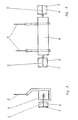
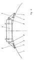
- the work platform 4 of an access system shown in FIG. 1 is only suspended from the superstructure 2 by means of the driving and guide ropes 3, which is mounted on the upper edge of a cylindrical structure. In a known manner, this superstructure 2 can make a circular trip around the edge of this cylindrical structure.
- the work platform 4 has an articulated boom 5 on each side, which carries a magnetic plate 6 at each end.
- the work platform 4 is held securely on the building surface 1 by means of the magnetic plates 6.
- Each magnetic plate 6 is guided on the building surface 1 by means of ball rollers 7.
- the work platform 4 has castors 8 which, as indicated schematically in FIG. 4, are placed transversely during horizontal travel. When moving vertically, these castors 8 are rotated by 90 °.
Description
- Die Erfindung betrifft eine Befahranlage nach dem Oberbegriff des Anspruchs 1.
- Derartige Befahranlagen werden insbesondere an Bauwerken mit gleichbleibendem oder veränderlichem kreisförmigen Grundriß eingesetzt, beispielsweise an Schornsteinen, die als Kreiszylinder oder Kegelstumpf, oder an Fernmeldetürmen, die als Rotationsparaboloid, oder Kühltürmen, die als Rotationshyperboloid gestaltet sind oder ähnlichen Bauwerken. Die Befahranlagen können beispielsweise zur Durchführung von Betonsanierungen oder an Stahlkonstruktionen zur Erneuerung des Korrisionsschutzes eingesetzt werden.
- Die bekannten Befahranlagen weisen eine Arbeitsbühne, insbesondere aus Leichtmetall auf, die mit Spezialwinden an Fahrseilen auf und ab bewegt werden kann. Am Oberrand des Bauwerkes ist ein Oberwagen (wie z.B. aus der DE-U-18 668 76 bekannt) vorgesehen, der eine Kreisfahrt ausführen kann. Die Arbeitsbühne ist mittels Fahr- und Führungsseilen am Oberwagen angehängt. Die bekannten Befahranlagen weisen ferner Spannseile auf, die verspannt werden und damit die Arbeitsbühne bei Windeinwirkung in ihrer Lage fixieren und gegen Pendeln sowohl radial als auch tangential sichern. Diese Spannseile sind am Fuß an Konsolen befestigt, die an Schienen verfahrbar sind.
- Die für den sicheren Betrieb erforderliche Vorspannkraft ist im wesentlichen von der Bauhöhe zwischen dem Oberwagen und den unteren Schienen abhängig. Erhöhte Vorspannkräfte sind beispielsweise bei Befahranlagen für die inneren Wandflächen von Kühltürmen erforderlich. In diesem Fällen muß ein zusätzlicher Anpressdruck der Arbeitsbühne in den Bereichen erzeugt werden, die gegenüber dem oberen Anhängepunkt nach außen versetzt liegen.
- Für Befahranlagen an den Außenflächen derartiger Bauwerke sind zusätzliche Hilfsanlagen erforderich, um die Arbeitsbühne an das Bauwerk anzudrücken.
- Aus der DE-OS 20 14 102 ist eine derartige Arbeitsbühne bekannt, die Gebläse aufweist, mittels derer zwischen der Hängebühne und der Wand eine Unterdruckzone erzeugt wird, um durch Saugwirkung diese Arbeitsbühne an der Wand zu halten. Alternativ kann mittels dieser Gebläse gegen die Wand geblasen werden, um zwischen der Wand und der Arbeitsbühne ein Druckluftkissen zu erzeugen, welches die Arbeitsbühne in einem bestimmten Abstand von der Wand hält.
- Die DE-G 85 31 513 U1 beschreibt eine Hilfskonstruktion, bei der an oder in der Arbeitsbühne mindestens eine, eine Schubkraft erzeugende Strömungsmaschine montiert ist, deren Druckseite an der der Wand abgewandten Seite der Arbeitsbühne angeordnet und von der Wand weggerichtet ist.
- Der Erfindung liegt die Aufgabe zugrunde, die Arbeitsbühne einer derartigen Befahranlage so zu gestalten, daß die bekannten Spannseile entfallen, die Arbeitsbühne aber dennoch an gekrümmten Flächen zuverlässig gegen das Bauwerk gedrückt, in zwei senkrecht zueinander stehenden Richtungen verfahrbar ist und ein Pendeln und Ausschwingen sicher verhindert wird.
- Erfindungsgemäß wird diese Aufgabe durch den Inhalt des Anspruchs 1 gelöst.
- Die Magnetplatten, die an beiden Seiten der Arbeitsbühne mittels Auslegern angelenkt sind, halten die Arbeitsbühne an Bauwerkflächen, die aus Stahlbeton oder Stahl bestehen, sicher fest. Die Magnetplatte ist mit Kugelrollen ausgerüstet, mittels derer sie auf der Bauwerksfläche geführt wird. Durch das Verhindern des Pendelns und Ausschwingens wird die Betriebssicherheit erhöht und die arbeitspsychologischen sowie physiologischen Bedingungen für die Arbeitskräfte auf der Arbeitsbühne verbessert. Die Spannseile, die eine erhebliche Eigenlast besitzen und insbesondere in großer Höhe eine beträchtliche Windangriffsfläche darstellen, können entfallen. Damit entfällt auch das aufwendige Vorspannen der Seile und die zur Konstanthaltung der Vorspannung erforderlichen Einrichtungen. Da das Vorspannen entfällt, kann der Oberwagen leichterer Bauweise ausgeführt werden. Dies ist hinsichtlich der Tragfähigkeit des Bauwerkes, insbesondere bei am Kopf von Schornsteinen oder Kühltürmen vorliegenden Schäden von besonderer Bedeutung.
- Ferner entfällt die aufwendige Herstellung und Anbringung der unteren Führungsschiene einschließlich der dafür notwendigen Stützkonsolen.
- Mit Vorteil ist die Magnetplatte als Permanent-Magnet ausgebildet. Bei dieser Ausführungsform ist keine Speisung erforderlich.
- Bei einer anderen vorteilhaften Ausführungsform ist in der Magnetplatte ein Elektromagnet und ein Stromspeicher eingebaut. Der Stromerzeuger für die Elektromagneten befindet sich in der Arbeitsbühne. Vorteilhafterweise kann der Stromspeicher bzw. der Stromerzeuger die Antriebe auch für die Vertikal- und Kreisfahrt speisen. Die Anordnung der Stromerzeuger oder Stromspeicher in der Arbeitsbühne hat den besonderen Vorteil, die Befahranlage ohne Versorgungskabel betreiben zu können.
- Die Magnetstärke ist von den jeweiligen Arbeitsbedingungen abhängig. Sie wird von den Bauwerksparametern wie beispielsweise der Höhe, der Form oder vom Material bestimmt.
- Die Arbeitsbühne ist mit Lenkrollen ausgerüstet, die bei der Horizontalfahrt quer und bei der Vertikalfahrt längst gestellt werden können. Wird die Befahranlage bei gekrümmten Bauwerkformen, beispielsweise an Kühltürmen eingesetzt, wird ein Neigungsausgleich durchgeführt. Bei extremen Bauwerkformen sind die Lenkrollen mit Vorteil als Kugelrollen ausgebildet.
- Ein Ausführungsbeispiel der Erfindung soll in der folgenden Beschreibung unter Bezugnahme auf die Fig. der Zeichnungen erläutert werden.
- Es zeigen:
- Fig. 1: eine schematische Ansicht einer, an einem zylindrischen Bauwerk montierten Befahranlage,
- Fig. 2: eine schematische Seitenansicht der Befahranlage,
- Fig. 3: ein schematische Vorderansicht der Befahranlage und
- Fig. 4: ein schematische Draufsicht auf eine an eine Kreiszylinderfläche angedrückte Befahranlage.
- Die in Fig. 1 dargestellte Arbeitsbühne 4 einer Befahranlage ist lediglich mittels der Fahr- und Führungsseile 3 am Oberwagen 2 aufgehängt, der am oberen Rand eines zylinderischen Bauwerkes montiert ist. In bekannter weise kann dieser Oberwagen 2 um den Rand dieses zylinderischen Bauwerkes herum eine Kreisfahrt durchführen.
- Die Arbeitsbühne 4 weist auf jeder Seite einen angelenkten Ausleger 5 auf, der an seinem Ende jeweils eine Magnetplatte 6 trägt.
- Wie die Fig. 1 und 4 zeigen, wird die Arbeitsbühne 4 mittels der Magnetplatten 6 sicher an der Bauwerkfläche 1 gehalten.
- Jede Magnetplatte 6 ist mittels Kugelrollen 7 auf der Bauwerksfläche 1 geführt.
- Die Arbeitsbühne 4 weist Lenkrollen 8 auf, die, wie in Fig. 4 schematisch angedeutet, bei Horizontalfahrt quer gestellt sind. Bei Vertikalfahrt werden diese Lenkrollen 8 um 90° gedreht.
Claims (6)
- Befahranlage für Außen- oder Innenwände von Bauwerken aus Stahlbeton oder Stahl, deren1. Arbeitsbühne (4) mittels Fahr- und Führungsseilen (3) an einem,2. am oberen Rand des Bauwerks verfahrbaren Oberwagen (2) angehängt und3. mittels eines Motorantriebes längs dieser Seile vertikal verfahrbar ist,
dadurch gekennzeichnet, daß4. an beiden Seiten der Arbeitsbühne (4) je ein Ausleger (5) angelenkt ist, der5. an seinem Ende eine Magnetplatte (6) trägt,5.1 die mit Kugelrollen (7) ausgerüstet ist mittels derer die Arbeitsbühne (4) auf der Bauwerksfläche (1) geführt wird. - Befahranlage nach Anspruch 1,
dadurch gekennzeichnet, daß5.1 die Magnetplatte (6) ein Permanent-Magnet ist. - Befahranlage nach Anspruch 1,
dadurch gekennzeichnet, daß5.2 die Magnetplatte (6) ein Elektromagnet ist. - Befahranlage nach Anspruch 3,
dadurch gekennzeichnet, daß5.2.1 ein Stromspeicher oder Stromerzeuger für die Elektromagneten in der Arbeitsbühne (4) montiert ist. - Befahranlage nach mindestens einem der Ansprüche 1 - 4,
dadurch gekennzeichnet, daß4.1 die Arbeitsbühne (4) mit Lenkrollen (8) ausgerüstet ist. - Befahranlage nach Anspruch 5,
dadurch gekennzeichnet, daß4.1.1 die Lenkrollen (8) als Kugelrollen ausgebildet sind.
Priority Applications (1)
| Application Number | Priority Date | Filing Date | Title |
|---|---|---|---|
| AT89730143T ATE81878T1 (de) | 1988-06-30 | 1989-06-14 | Befahranlage. |
Applications Claiming Priority (2)
| Application Number | Priority Date | Filing Date | Title |
|---|---|---|---|
| DE3822424 | 1988-06-30 | ||
| DE3822424A DE3822424A1 (de) | 1988-06-30 | 1988-06-30 | Befahranlage |
Publications (3)
| Publication Number | Publication Date |
|---|---|
| EP0349476A2 EP0349476A2 (de) | 1990-01-03 |
| EP0349476A3 EP0349476A3 (en) | 1990-05-09 |
| EP0349476B1 true EP0349476B1 (de) | 1992-10-28 |
Family
ID=6357813
Family Applications (1)
| Application Number | Title | Priority Date | Filing Date |
|---|---|---|---|
| EP89730143A Expired - Lifetime EP0349476B1 (de) | 1988-06-30 | 1989-06-14 | Befahranlage |
Country Status (7)
| Country | Link |
|---|---|
| US (1) | US4960185A (de) |
| EP (1) | EP0349476B1 (de) |
| AT (1) | ATE81878T1 (de) |
| CA (1) | CA1299222C (de) |
| DE (2) | DE3822424A1 (de) |
| ES (1) | ES2036368T3 (de) |
| GR (1) | GR3006835T3 (de) |
Families Citing this family (13)
| Publication number | Priority date | Publication date | Assignee | Title |
|---|---|---|---|---|
| DE3910484A1 (de) * | 1989-03-31 | 1990-10-04 | Siemens Ag | Loetvorrichtung |
| GB9908603D0 (en) * | 1999-04-16 | 1999-06-09 | W & R Lewis Limited | Access scaffolding scaffolding devices and method |
| ES2189671B2 (es) * | 2001-11-02 | 2004-09-16 | Servicios De Ingenieria Y Montaje, Alen, S.L. | Andamio para aerogeneradores con fuste de seccion variable. |
| ES2244292A1 (es) * | 2003-09-19 | 2005-12-01 | Peri, S.A. | Dispositivo elevador de personas por el fuste de un aerogenerador. |
| HK1172197A2 (en) * | 2012-06-01 | 2013-04-12 | Wls Intellectual Property Ltd | Improvements in building components and structures |
| DE102012105417B4 (de) * | 2012-06-21 | 2014-02-20 | GESTA Gesellschaft für Stahlrohrgerüste mit beschränkter Haftung | Befahranlage für überhängende oder konvex gekrümmte Wände |
| DE102012105420A1 (de) * | 2012-06-21 | 2013-12-24 | GESTA Gesellschaft für Stahlrohrgerüste mit beschränkter Haftung | Oberwagen einer Befahranlage |
| US9410331B2 (en) | 2013-06-17 | 2016-08-09 | Sky Climber Access Solutions Atlanta Llc | Magnetic anchor system for suspension work equipment, method of remotely attaching a suspended work platform to a work structure, and a system and device for same |
| CN103643789B (zh) * | 2013-12-17 | 2016-01-13 | 青海鹏盛电力器材有限公司 | 一种电力钢管塔可翻转安全检修平台 |
| CN104278828B (zh) * | 2014-09-30 | 2016-08-24 | 北京首钢建设集团有限公司 | 一种混凝土烟囱拆除操作平台 |
| US20190047824A1 (en) * | 2016-03-22 | 2019-02-14 | Vestas Wind Systems A/S | Wind turbine descent system |
| CN114704068B (zh) * | 2022-06-07 | 2022-08-19 | 中铁城建集团第一工程有限公司 | 附着式升降脚手架系统 |
| CN115419248B (zh) * | 2022-08-25 | 2023-06-13 | 广州德峰机电工程有限公司 | 一种空调外机用座架及其施工方法 |
Family Cites Families (17)
| Publication number | Priority date | Publication date | Assignee | Title |
|---|---|---|---|---|
| US2881029A (en) * | 1956-04-02 | 1959-04-07 | Lief W Tollefsen | Portable scaffolding |
| FR1158786A (fr) * | 1956-07-25 | 1958-06-19 | Nettoyeuse-brosseuse sous-marine | |
| GB1024741A (en) * | 1961-06-19 | 1966-04-06 | Borge Tage Hestehave | Process and apparatus for moulding hollow articles |
| DE1866876U (de) * | 1962-11-29 | 1963-02-07 | Emil Domes | Fahrbares haengegeruest mit spannvorrichtungen fuer fuehrungsseile. |
| US3114433A (en) * | 1963-01-04 | 1963-12-17 | Downs Cas Arnold | Traveling scaffold |
| US3375900A (en) * | 1966-06-13 | 1968-04-02 | George R. Conley | Worker support device |
| DE1759543A1 (de) * | 1967-05-15 | 1971-06-16 | Gen Conveyor Inc Of Northern C | Bewegliches Bau- oder Haengegeruest |
| US3537545A (en) * | 1968-10-23 | 1970-11-03 | James E Willis | Positioning device for elevated structures |
| GB1250131A (de) * | 1969-03-25 | 1971-10-20 | ||
| FR2145115A5 (de) * | 1971-07-06 | 1973-02-16 | Cemat | |
| US3837428A (en) * | 1973-06-27 | 1974-09-24 | L Gish | Safety scaffold with electromagnets |
| GB1512817A (en) * | 1974-11-14 | 1978-06-01 | Walcker & Co Kg | Transporting and retaining apparatus |
| SE7511712L (sv) * | 1975-10-20 | 1977-04-21 | Ralf Larson | Anordning for ytbehandling av foremal med stora ytor t ex fartyg, cisterner eller liknande |
| US4120378A (en) * | 1977-03-07 | 1978-10-17 | Mills Ernest E | Movable work support for cylindrical structures |
| US4355699A (en) * | 1980-11-24 | 1982-10-26 | Smith Jr Charles P | Emergency rescue system |
| US4421205A (en) * | 1982-02-01 | 1983-12-20 | The United States Of America As Represented By The Secretary Of The Navy | Magnetic ship's hog line holder |
| DE8531513U1 (de) * | 1985-11-05 | 1986-01-02 | Gesta Gesellschaft für Stahlrohrgerüste mbH, 1000 Berlin | Hängebühne für eine überhängende Wand |
-
1988
- 1988-06-30 DE DE3822424A patent/DE3822424A1/de active Granted
-
1989
- 1989-06-14 DE DE8989730143T patent/DE58902542D1/de not_active Expired - Fee Related
- 1989-06-14 AT AT89730143T patent/ATE81878T1/de not_active IP Right Cessation
- 1989-06-14 ES ES198989730143T patent/ES2036368T3/es not_active Expired - Lifetime
- 1989-06-14 EP EP89730143A patent/EP0349476B1/de not_active Expired - Lifetime
- 1989-06-29 US US07/373,866 patent/US4960185A/en not_active Expired - Fee Related
- 1989-06-30 CA CA000604638A patent/CA1299222C/en not_active Expired - Lifetime
-
1993
- 1993-01-21 GR GR930400086T patent/GR3006835T3/el unknown
Also Published As
| Publication number | Publication date |
|---|---|
| CA1299222C (en) | 1992-04-21 |
| ATE81878T1 (de) | 1992-11-15 |
| DE3822424A1 (de) | 1990-01-04 |
| GR3006835T3 (de) | 1993-06-30 |
| US4960185A (en) | 1990-10-02 |
| DE58902542D1 (de) | 1992-12-03 |
| ES2036368T3 (es) | 1993-05-16 |
| DE3822424C2 (de) | 1990-04-12 |
| EP0349476A3 (en) | 1990-05-09 |
| EP0349476A2 (de) | 1990-01-03 |
Similar Documents
| Publication | Publication Date | Title |
|---|---|---|
| EP0349476B1 (de) | Befahranlage | |
| EP1857670B1 (de) | Vorrichtung zum Errichten eines aus einzelnen Turmsegmenten zusammengesetzten Turms einer Windenergieanlage | |
| DE69822303T2 (de) | Teilweise einziehbare bauplattform | |
| EP0501140A1 (de) | In einem Aufzugsschacht verfahrbares Montagegerüst zur Montage von Schachtausrüstung | |
| DE4339638A1 (de) | Befahranlage für Außenwände von Bauwerken mit annähernd kreisförmigem, elliptischem bzw. vieleckigem Querschnitt aus Stahl, Stahlbeton oder anderen festen Stoffen, insbesondere für Windkraftanlagen mit nicht vertikaler Drehachse des Rotors | |
| EP2161236B1 (de) | Regalbediengerät mit einem Fahrwerk | |
| DE202021102638U1 (de) | Hebevorrichtung für Stahlschienen | |
| DE3420737A1 (de) | Zusatzeinrichtung fuer hoehenverstellbare arbeitsgerueste | |
| WO2018024297A1 (de) | Brückenstützeinrichtung zum abstützen eines brückensegments und verfahren zum betrieb von brückenstützeinrichtungen | |
| DE3911868C2 (de) | ||
| WO2020088979A1 (de) | Verfahren zum installieren einer aufzugsanlage | |
| DD244274A3 (de) | Geruest fuer reparaturarbeiten an fassaden und dachtraufen | |
| DE19803954B4 (de) | Verfahren und Vorrichtung zum Erhöhen von Masten | |
| EP0626339A1 (de) | Hängekran mit einer Arbeitsplattform-Konstruktion, insbesondere für die Flugzeugwartung | |
| WO2000004255A1 (de) | Vorrichtung zum abbrechen eines eine umlaufende wandung aufweisenden bauwerks wie einem schornstein oder einem kühlturm | |
| EP4172096A1 (de) | Verfahren zum errichten einer aufzugsanlage sowie zur durchführung des verfahrens geeignete aufzugsanlage | |
| EP1362821B1 (de) | Portalhubwagen | |
| DE4138559C2 (de) | Fahrbarer Konsolkran | |
| DE102019122021A1 (de) | Montagetraverse und Verfahren zum Einziehen von kabelförmigen Elementen, insbesondere von Spanngliedern, entlang eines Turms einer Windenergieanlage | |
| WO2004051002A2 (de) | Vorrichtung zum anlegen eines wasserfahrzeuges an einem wasserbauwerk | |
| DE2157669A1 (de) | Verfahren und vorrichtung zum montieren eines bauwerkes, insbesondere eines bockkranes | |
| EP1170189B1 (de) | Gleissysteme für eine Werkstatthalle | |
| EP1772413A1 (de) | Aufzug (Rucksackaufzug mit am Fahrkorbrahmen aufgehängter Kabine) | |
| DE102022110726A1 (de) | Kranaufbocksystem | |
| DD145850A3 (de) | Ausleger,insbesondere fuer einen e senbahnkran |
Legal Events
| Date | Code | Title | Description |
|---|---|---|---|
| PUAI | Public reference made under article 153(3) epc to a published international application that has entered the european phase |
Free format text: ORIGINAL CODE: 0009012 |
|
| AK | Designated contracting states |
Kind code of ref document: A2 Designated state(s): AT BE CH DE ES FR GB GR IT LI LU NL SE |
|
| PUAL | Search report despatched |
Free format text: ORIGINAL CODE: 0009013 |
|
| AK | Designated contracting states |
Kind code of ref document: A3 Designated state(s): AT BE CH DE ES FR GB GR IT LI LU NL SE |
|
| 17P | Request for examination filed |
Effective date: 19900702 |
|
| 17Q | First examination report despatched |
Effective date: 19910605 |
|
| GRAA | (expected) grant |
Free format text: ORIGINAL CODE: 0009210 |
|
| AK | Designated contracting states |
Kind code of ref document: B1 Designated state(s): AT BE CH DE ES FR GB GR IT LI LU NL SE |
|
| REF | Corresponds to: |
Ref document number: 81878 Country of ref document: AT Date of ref document: 19921115 Kind code of ref document: T |
|
| REF | Corresponds to: |
Ref document number: 58902542 Country of ref document: DE Date of ref document: 19921203 |
|
| ITF | It: translation for a ep patent filed |
Owner name: BUGNION S.P.A. |
|
| ET | Fr: translation filed | ||
| GBT | Gb: translation of ep patent filed (gb section 77(6)(a)/1977) |
Effective date: 19930114 |
|
| REG | Reference to a national code |
Ref country code: ES Ref legal event code: FG2A Ref document number: 2036368 Country of ref document: ES Kind code of ref document: T3 |
|
| REG | Reference to a national code |
Ref country code: GR Ref legal event code: FG4A Free format text: 3006835 |
|
| PLBE | No opposition filed within time limit |
Free format text: ORIGINAL CODE: 0009261 |
|
| STAA | Information on the status of an ep patent application or granted ep patent |
Free format text: STATUS: NO OPPOSITION FILED WITHIN TIME LIMIT |
|
| 26N | No opposition filed | ||
| EPTA | Lu: last paid annual fee | ||
| EAL | Se: european patent in force in sweden |
Ref document number: 89730143.8 |
|
| PGFP | Annual fee paid to national office [announced via postgrant information from national office to epo] |
Ref country code: FR Payment date: 19950517 Year of fee payment: 7 |
|
| PGFP | Annual fee paid to national office [announced via postgrant information from national office to epo] |
Ref country code: GB Payment date: 19950605 Year of fee payment: 7 |
|
| PGFP | Annual fee paid to national office [announced via postgrant information from national office to epo] |
Ref country code: CH Payment date: 19950621 Year of fee payment: 7 |
|
| PGFP | Annual fee paid to national office [announced via postgrant information from national office to epo] |
Ref country code: AT Payment date: 19950623 Year of fee payment: 7 |
|
| PGFP | Annual fee paid to national office [announced via postgrant information from national office to epo] |
Ref country code: SE Payment date: 19950626 Year of fee payment: 7 |
|
| PGFP | Annual fee paid to national office [announced via postgrant information from national office to epo] |
Ref country code: NL Payment date: 19950628 Year of fee payment: 7 |
|
| PGFP | Annual fee paid to national office [announced via postgrant information from national office to epo] |
Ref country code: GR Payment date: 19950630 Year of fee payment: 7 Ref country code: ES Payment date: 19950630 Year of fee payment: 7 Ref country code: DE Payment date: 19950630 Year of fee payment: 7 |
|
| PGFP | Annual fee paid to national office [announced via postgrant information from national office to epo] |
Ref country code: LU Payment date: 19950701 Year of fee payment: 7 |
|
| PGFP | Annual fee paid to national office [announced via postgrant information from national office to epo] |
Ref country code: BE Payment date: 19950712 Year of fee payment: 7 |
|
| PG25 | Lapsed in a contracting state [announced via postgrant information from national office to epo] |
Ref country code: LU Free format text: LAPSE BECAUSE OF NON-PAYMENT OF DUE FEES Effective date: 19960614 Ref country code: GB Effective date: 19960614 Ref country code: AT Effective date: 19960614 |
|
| PG25 | Lapsed in a contracting state [announced via postgrant information from national office to epo] |
Ref country code: SE Effective date: 19960615 Ref country code: ES Free format text: LAPSE BECAUSE OF EXPIRATION OF PROTECTION Effective date: 19960615 |
|
| PG25 | Lapsed in a contracting state [announced via postgrant information from national office to epo] |
Ref country code: LI Effective date: 19960630 Ref country code: CH Effective date: 19960630 Ref country code: BE Effective date: 19960630 |
|
| BERE | Be: lapsed |
Owner name: GESTA G.- FUR STAHLROHRGERUSTE M.B.H. Effective date: 19960630 |
|
| PG25 | Lapsed in a contracting state [announced via postgrant information from national office to epo] |
Ref country code: GR Free format text: THE PATENT HAS BEEN ANNULLED BY A DECISION OF A NATIONAL AUTHORITY Effective date: 19961231 |
|
| PG25 | Lapsed in a contracting state [announced via postgrant information from national office to epo] |
Ref country code: NL Effective date: 19970101 |
|
| REG | Reference to a national code |
Ref country code: GR Ref legal event code: MM2A Free format text: 3006835 |
|
| GBPC | Gb: european patent ceased through non-payment of renewal fee |
Effective date: 19960614 |
|
| REG | Reference to a national code |
Ref country code: CH Ref legal event code: PL |
|
| PG25 | Lapsed in a contracting state [announced via postgrant information from national office to epo] |
Ref country code: FR Effective date: 19970228 |
|
| EUG | Se: european patent has lapsed |
Ref document number: 89730143.8 |
|
| NLV4 | Nl: lapsed or anulled due to non-payment of the annual fee |
Effective date: 19970101 |
|
| REG | Reference to a national code |
Ref country code: FR Ref legal event code: ST |
|
| PG25 | Lapsed in a contracting state [announced via postgrant information from national office to epo] |
Ref country code: DE Effective date: 19970701 |
|
| REG | Reference to a national code |
Ref country code: ES Ref legal event code: FD2A Effective date: 20000601 |
|
| PG25 | Lapsed in a contracting state [announced via postgrant information from national office to epo] |
Ref country code: IT Free format text: LAPSE BECAUSE OF NON-PAYMENT OF DUE FEES;WARNING: LAPSES OF ITALIAN PATENTS WITH EFFECTIVE DATE BEFORE 2007 MAY HAVE OCCURRED AT ANY TIME BEFORE 2007. THE CORRECT EFFECTIVE DATE MAY BE DIFFERENT FROM THE ONE RECORDED. Effective date: 20050614 |