EP0349430B1 - Gerät mit rotierender Kopftrommel - Google Patents
Gerät mit rotierender Kopftrommel Download PDFInfo
- Publication number
- EP0349430B1 EP0349430B1 EP89401858A EP89401858A EP0349430B1 EP 0349430 B1 EP0349430 B1 EP 0349430B1 EP 89401858 A EP89401858 A EP 89401858A EP 89401858 A EP89401858 A EP 89401858A EP 0349430 B1 EP0349430 B1 EP 0349430B1
- Authority
- EP
- European Patent Office
- Prior art keywords
- rotary
- drum member
- stationary
- bore
- shaft
- Prior art date
- Legal status (The legal status is an assumption and is not a legal conclusion. Google has not performed a legal analysis and makes no representation as to the accuracy of the status listed.)
- Expired - Lifetime
Links
Images

Classifications
-
- G—PHYSICS
- G11—INFORMATION STORAGE
- G11B—INFORMATION STORAGE BASED ON RELATIVE MOVEMENT BETWEEN RECORD CARRIER AND TRANSDUCER
- G11B5/00—Recording by magnetisation or demagnetisation of a record carrier; Reproducing by magnetic means; Record carriers therefor
- G11B5/48—Disposition or mounting of heads or head supports relative to record carriers ; arrangements of heads, e.g. for scanning the record carrier to increase the relative speed
- G11B5/52—Disposition or mounting of heads or head supports relative to record carriers ; arrangements of heads, e.g. for scanning the record carrier to increase the relative speed with simultaneous movement of head and record carrier, e.g. rotation of head
- G11B5/53—Disposition or mounting of heads on rotating support
Definitions
- the present invention relates generally to a rotary head drum apparatus having rotary and stationary drum members, and more particularly is directed to an arrangement through which signals are transmitted between the stationary drum member and each magnetic head attached to the rotary drum member in a magnetic recording and reproducing apparatus such as a video tape recorder and the like.
- a video tape recorder generally includes a rotary head drum assembly or apparatus which comprises a rotary drum member having at least one magnetic head attached thereto and a stationary drum member located just below the rotary drum member, with a magnetic tape being helically wrapped around the rotary and stationary drum members.
- a rotary head drum assembly or apparatus which comprises a rotary drum member having at least one magnetic head attached thereto and a stationary drum member located just below the rotary drum member, with a magnetic tape being helically wrapped around the rotary and stationary drum members.
- the magnetic head and the rotor of the rotary transformer have to be electrically connected to each other.
- a joint base plate to which there are soldered a lead wire extending from the magnetic or video head and a lead wire extending from a rotor of the rotary transformer.
- a connector comprised of a plug pin and a plug socket which, when the head drum apparatus is assembled are electrically connected to each other.
- a relatively large force is required to insert the plug pin into the plug socket so that a load is applied to a bearing or the like. Therefore, a rotary head drum apparatus of this kind is undesirably influenced by such large insertion force which causes the magnetic head initially mounted on the rotary drum with high accuracy to be displaced from its desired position.
- the rotary head drum member has to be connected to ground through a cable extending between the head drum and a head amplifier.
- a joint base plate is attached to the lower surface of the stationary drum, for example, by a screw, and a ground contact is connected to the joint base plate.
- the head drum may be deformed thereby so that the tracking accuracy is deteriorated, and the resulting picture is disturbed accordingly.
- a support shaft has a press fit in a bore of the lower stationary drum member and the upper rotary drum member is rotatably supported by the support shaft via a bearing.
- a so-called shrink-fit process is employed.
- the stationary drum member is heated to 150°C or more so that its bore is diametrically expanded and, while the stationary drum member is in this heated condition, the support shaft is easily fitted into the bore of the stationary drum.
- the stationary drum member cools down to ambient temperature, the bore contracts on the support shaft and seizes the latter.
- the shrink-fit process has the following advantages. If the support shaft is press-fitted into the bore of the stationary drum member at room temperature, then the support shaft will dig into the inner surface of the bore of the stationary drum member. As a result, the support shaft cannot be precisely axially located in the bore of the stationary drum member. On the other hand, when the stationary drum member is heated so as to temporarily increase the inner diameter of the bore, the support shaft can be fitted into the bore with a small inserting force. Hence, the inner surface of the bore of the stationary drum member can be protected from being scored or cut, and the support shaft can be fitted into the bore with a high degree of accuracy in the axial or vertical direction.
- the shrink-fit process cannot avoid the following defects. If the stationary drum is heated in order to fit the support shaft into the bore thereof, as in the shrink-fit process, then the coil of the rotary transformer attached to the stationary drum member may be burned. Further, the shrink-fit process decreases the bonding force of the bonding agent which secures the rotary transformer to the stationary drum member. There is then a possibility that the rotary transformer will be detached from the stationary drum member. Therefore, the shrink-fit process cannot be applied to a rotary head drum apparatus of the type in which the rotary transformer is secured to the stationary drum member by an adhesive or bonding agent.
- the means defined in sub-claim 9 enable a stationary drum member to be positively connected to ground without being warped or distorted, as when a joint base plate having a ground contact pin is attached to the lower surface of the stationary drum member by screws or the like.
- a support shaft can be fitted into a bore of a stationary drum member at room temperature so that a rotary transformer having its stator attached to the stationary drum member will not be affected thereby.
- the support shaft can be fitted into a bore of a stationary drum member with high accuracy in the vertical direction.
- the present rotary head drum apparatus is particularly suited for incorporation in a magnetic recording and reproducing apparatus, such as a video tape recorder and the like.
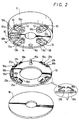
- a rotary head drum apparatus generally comprises a rotary drum member 11 having at least one magnetic head 10 mounted thereon, and a stationary drum member 12 that is disposed coaxially below the rotary drum member 11.
- Each magnetic head 10 is mounted at the radially outer end of a respective head base 13 which is secured to the lower surface of the rotary drum member 11 by a screw 14.
- a contactor 16 is attached to a terminal plate 15 for each magnetic head 10 for electrically connecting the respective magnetic head 10 with a rotor 18 of a rotary transformer 17.
- the rotary transformer 17 is used to transmit signals between the rotary drum member 11 and the stationary drum member 12.
- the rotor 18 of the rotary transformer 17 is attached to the rotary drum member 11 for rotation with the latter, while its stator 19 is attached to the stationary drum member 12.
- the rotor 18 and the stator 19 are axially opposed to each other with a very small air gap therebetween.
- each magnetic head 10 mounted on the rotary drum member 11 and the rotor 18 of the rotary transformer 17 will now be further described in detail with reference to Fig. 2 (and, in particular, with reference to the enlarged, side view encircled by an elliptical solid line in Fig. 2) and to Fig. 3.
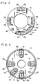
- the contactor 16 provided on the terminal plate 15 for each magnetic head 10 is formed of two leaf springs 16 a and 16 b each having an L-shaped configuration.
- a signal is transmitted between the magnetic head 10 and the rotor 18 of the rotary transformer 17.
- the contact surfaces of springs 16 a and 16 b and the contact portions 13 a and 13 b on the respective head base are plated with gold for increasing the conductivity therebetween.
- the head 10 may be simultaneously electrically connected to the rotor 18 of the rotary transformer 17.
- the terminal plate 15 is adhesively bonded or otherwise attached to the upper surface of the rotor 18 of the rotary transformer 17, and lead wires (not shown) extend from coils 18 a (Fig. 1) of the rotor 18 and are soldered to terminals 21 a and 21 b formed on the terminal plate 15 between each pair of the contactor springs 16 a and 16 b and being electrically connected thereto.
- the terminal plate 15 has an upwardly directed positioning pin 15a extending therefrom and being engageable in a positioning aperture 11a provided in the rotary drum member 11 for circumferentially positioning the terminal plate 15 in respect to the rotary drum member 11.
- Such circumferential positioning of the terminal plate 15 relative to the rotary drum member 11 ensures that, upon assembly of the rotary head drum apparatus, the pairs of contactor springs 16 a and 16 b which are angularly spaced apart around the terminal plate 15, as shown on Fig. 2 will be angularly aligned with the respective angularly spaced apart heads 10 on the rotary head member 11, and thus will be engageable with the associated contact portions 13 a and 13 b on the head bases 13.
- the rotary drum member 11 with the magnetic heads 10 mounted thereon is assembled on the boss 20 and secured to the latter by means of a screw 23.
- the boss 20 is rotatably mounted by means of ball bearings 24 and 25 on the upper portion of a supporting shaft 26.
- the lower end portion of the supporting shaft 26 is axially press-fitted into a bore 27 extending axially through the center of the stationary drum member 12.
- a flexible printed circuit board 28 has a terminal plate 29 mounted on an end portion thereof for attachment to the underside of the stationary drum member 12, as shown on Fig. 1.
- Signal transmitting pins 30 and ground contact pins 31 for grounding the stationary drum member 12 are implanted in the terminal plate 29 and will be hereinafter further described in detail.
- a motor 34 (Fig. 1) is located within the rotary drum member 11 for effecting rotation of the latter about the supporting shaft 26 relative to the stationary drum member 12. More specifically, the motor 34 is shown to include a stator yoke 35 which is secured to the rotary drum member 11 by a screw 36 and a magnet 37 adhesively bonded or otherwise secured to the stator yoke 35.
- a printed circuit board 38 located above the magnet 37 is fixed by a screw 40 to a boss 39 which is fixedly located on the upper end portion of the supporting shaft 26.
- the printed circuit board 38 includes a coil (not shown) which is in operative opposing relation to the magnet 37.
- a terminal plate 42 attached to an end portion of a flexible base plate 41 is also secured to the boss 39 by means of the screw 40, and the previously mentioned coil formed on the printed circuit board 38 receives the driving current for the motor 34 by way of suitable leads on the flexible base plate 41.
- the electrical connections between the magnetic heads 10 and the rotor 18 of the rotary transformer 17 are not provided by a soldering process that has to be conducted near to the rotary head drum apparatus, there is no danger that flux or solder balls will undesirably enter the rotary head drum apparatus.
- the springs 16 a and 16 b of the contactors 16 are flexed to engage the respective contact portions 13 a and 13 b on the head bases with relatively light resilient contacting forces, the magnetic heads 10 can be reliably and accurately mounted on the respective head bases 13 without the danger that such head bases will be warped or distorted by excessive forces applied thereto in achieving the necessary contacts.
- the contact portions 13 a and 13 b are formed on the bases 13 supporting the magnetic heads 10 and the respective resilient contactors 16 are provided on the terminal plate 15 positioned above the rotor 18 of the rotary transformer 17 in the illustrated embodiment of the invention, it will be apparent that the positions of the contact portions 13 a and 13 b and the resilient contactors 16 may be reversed.
- the resilient contactors 16 can depend from the undersides of the head bases 13 for resiliently engaging the contact portions 13 a and 13 b which, in that case, are provided on the terminal plate 15.
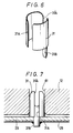
- each ground contact pin 31 is formed of a conductive metal sheet material and preferably includes a generally cylindrical body having diametrically opposed longitudinally directed slits 31A and 31′A.
- the slit 31A as shown on Figs. 6 and 7, extends along the entire length of the cylindrical body while the opposing slit 31′A extends only along the upper portion of the cylindrical body which is radial resilient by reason of the slits 31A and 31′A.
- a lead portion 31B is directed downwardly from the lower end of the cylindrical body of the pin 31, preferably at the side of the latter having the partial slit 31′A.
- the lead portion 31B extends downwardly through the terminal plate 29 and the flexible printed circuit board 28, as shown on Figs. 5 and 7, and is soldered to a respective portion of the printed circuit on the board 28.
- the signal transmitting pins 30 directed upwardly from the terminal plate 29 and being similarly connected, as by solder, to the printed circuit on the board 28, are engaged in respective connectors 60 extending from the underside of the stator 19 in response to the positioning of the terminal plate 29 against the bottom surface of the stationary drum member 12.
- the longitudinally slit cylindrical bodies of the ground contact pins 31 are fitted axially into corresponding apertures 61 formed in the stationary drum member 12.
- the stationary drum member 12 is connected to ground by way of the pins 31 suitably electrically connected with the printed circuit on the board 28.
- the cylindrical bodies of the pins 31 are desirably normally dimensioned so that the axial insertion thereof into the apertures 61 is accompanied by radial contraction of the contact pins 31.
- the ground contact pins 31 are pressed against the surfaces of the respective apertures 61 by their resilient restoring forces for ensuring reliable electrical contact of the pins 31 with the stationary drum member 12 which is desirably formed of aluminum.
- the stationary drum member 12 can be conveniently and reliably connected to ground merely by the axial insertion of the pins 31 in the respective apertures 61, and without the need to employ screws for maintaining the engagement of the pins 31 in the apertures 61.
- the tracking accuracy of the magnetic head or heads can be ensured for avoiding disturbance of a video image to be reproduced by a VTR having the rotary head drum apparatus embodying this invention.
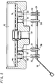
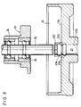
- the bore 27 extending axially through the center of the stationary drum member 12 is formed with two vertically spaced apart concave or undercut annuli 27A and 27B so as to define annular seating portions or lands 27C, 27D and 27E which are located axially above the concave annulus 27A, intermediate the concave annuli 27A and 27B, and below the concave annulus 27B, respectively.
- the supporting shaft 26 By reason of the concave annuli 27A and 27B at which the surface of the bore 27 is relieved, the supporting shaft 26, when being pressed axially downward into the bore 27, engages the surface of the bore only at the seating or land portions 27C, 27D and 27E in succession.
- the shaft 26 has a press fit within the bore 27 for suitably securing the shaft 26 relative to the stationary drum member 12, seizing or scoring of the shaft 26 or of the surface of the bore 27 is avoided during insertion of the shaft 26 into the bore 27. More specifically, as the supporting shaft 26 is urged axially downward into the bore 27, the shaft 26 initially only engages the surface of the land 27C.
- the axial dimensions of the first and second lands 27C and 27D are desirably in the range from about 0.1 to 0.3 mm, and the axial force that has to be applied to the shaft 26 for moving the latter downwardly past the lands 27C and 27D is preferably less than 10 kg.
- Such insertion of the shaft 26 to the extent required for engagement with the land 27D as well as with the land 27C is referred to as a preliminary fitting operation and ensures that, as the lower end of the shaft 26 nears the lowermost seating portion or land 27E, the shaft 26 will be precisely in axial alignment with the bore 27 and not canted in respect to the latter.
- the preliminary fitting operation during which the surface of the supporting shaft 26 engages only the relatively small areas of the lands 27C and 27D of relatively small area is effected with a relatively small axial force being applied to the shaft 26, the accurate axial alignment of the shaft 26 with the bore 27 can be reliably maintained.
- the fact that the shaft 26 is not inclined or canted relative to the bore 27 ensures that the main fitting operation can be smoothly and accurately carried out.
- the desired vertical position of the shaft 26, and hence of the heads 10 carried by the drum member 12 supported by the shaft can be achieved within a tolerance of only 2 »m.
- the supporting shaft may be inclined or canted relative to the axis of the bore into which it is being press-fitted and high accuracy in the vertical positioning of the shaft cannot be realized.
- magnetic tape is suitably guided so as to be wrapped around the outer peripheral surfaces of the rotary drum member 10 and the stationary drum member 12 which are coaxial with each other.
- the magnetic heads 10 extending from the bases 13 mounted on the rotary drum member 11 scan tracks extending obliquely across the magnetic tape for effecting helical scanning of the latter.
- signals are supplied from stationary recording circuits through the rotary transformer 17 to the magnetic heads 10 and are thereby recorded in the scanned tracks on the magnetic tape.
- signals recorded in the oblique tracks on the magnetic tape are read out therefrom by the magnetic heads scanning such tracks and the reproduced signals are supplied through the rotary transformer 17 to stationary reproducing circuits.
Landscapes
- Recording Or Reproducing By Magnetic Means (AREA)
Claims (12)
- Drehkopftrommelgerät, bei welchem wenigstens ein Magnetkopf (10) an einem Drehtrommelteil (11) zur Drehung relativ zu einer stationären Struktur (12) angebracht ist und ein Drehwandler (17) zur Übertragung elektrischer Signale zwischen dem Magnetkopf (10) und der stationären Struktur (12) vorgesehen ist und einen relativ zum Drehtrommelteil (11) fixierten Rotor (18) und einen relativ zur stationären Struktur (12) fixierten Stator (19) sowie jeweilige Spulen (18a, 19a) aufweist, dadurch gekennzeichnet, daß Mittel zum Verbinden des Magnetkopfes (10) mit der Spule des Rotors (18) des Drehwandlers (17) vorgesehen sind, die auf dem Drehtrommelteil (11) oder dem Rotor (18) befestigte elastischen Kontaktgebermittel (16a, 16b) und auf dem Rotor (18) bzw. dem Drehtrommelteil (11) Kontaktstückmittel (13a, 13b) für einen Kontakt mit den Kontaktgebermitteln (16a, 16b) aufweisen, wobei die Kontaktgebermittel (16a, 16b) in Abhängigkeit von einem Zusammensetzen des Drehtrommelteils (11) und des Drehwandlers (17) elastisch gegen die Kontaktstückmittel gedrückt sind,
dadurch gekennzeichnet,
daß die Kontaktelemente (16a, 16b) im wesentlichen L-förmig sind und zueinander gerichtete freie Endabschnitte aufweisen. - Drehkopftrommelgerät nach Anspruch 1, dadurch gekennzeichnet, daß die Kontaktstückmittel (13a, 13b) in einer Ebene senkrecht zur Drehachse des Drehtrommelteils (11) sich erstreckende Kontaktflächen aufweisen, daß die Kontaktgebermittel (16a, 16b) in Kontakt gegen die Kontaktflächen (13a, 13b) bringbar sind und in zur Drehachse parallelen Richtungen elastisch flexibel sind, und daß das Zusammensetzen des Drehtrommelteils (11) und des Drehwandlers (17) durch eine Verschiebung des Drehtrommelteils (11) relativ zur stationären Struktur (12) in Richtung der Drehachse, um die Kontaktgebermittel (16a, 16b) gegen die Kontaktflächen (13a, 13b) elastisch zu verbiegen, bewirkt wird.
- Drehkopftrommelgerät nach Anspruch 2, dadurch gekennzeichnet, daß die Kontaktgebermittel (16a, 16b) zwei Kontaktelemente mit Abschnitten aufweist, die in den zur zur Drehachse parallelen Richtungen elastisch flexibel sind.
- Drehkopftrommelgerät nach Anspruch 3, dadurch gekennzeichnet, daß die Kontaktgebermittel (16a, 16b) Anschlußteile (21a, 21b) zum Anschluß an eine Spule (18a) des Rotors (18) mittels Lot aufweist.
- Drehkopftrommelgerät nach Anspruch 4, dadurch gekennzeichnet, daß die Anschlußteile (21a, 21b) zwischen den Kontaktgeberelementen (16a, 16b) angeordnet sind.
- Drehkopftrommelgerät nach Anspruch 1, dadurch gekennzeichnet, daß die stationäre Struktur (12) ein mit dem Drehkopftrommelteil (11) koaxiales stationäres Trommelteil (11) und eine sich axial in dem stationären Trommelteil (12) erstreckende zentrale Bohrung (27) aufweist, daß ein Halterungsschaft (26) mit Preßsitz axial in die Bohrung (27) eingesetzt ist, und daß Lagermittel (24, 25) das Drehtrommelteil (11) drehbar auf dem Halterungsschaft (26) halten, wobei die Bohrung (27) ringförmige Vertiefungsmittel (27A, 27B) aufweist, um die Fläche der Bohrung (27) in axial mit Abstand voneinander angeordnete Stege (27C, 27D, 27E) zu unterteilen, so daß beim axialen Einsetzen des Schaftes (26) in die Bohrung (27) die Stege (27C, 27D, 27E) sukzessive von der Schaftoberfläche kontaktiert werden.
- Drehkopftrommelgerät nach Anspruch 6, dadurch gekennzeichnet, daß die ringförmigen Vertiefungsmittel zwei axial im Abstand voneinander angeordnete konkave ringförmige Vertiefungen (27A, 27B) aufweisen, welche die Fläche der Bohrung (27) in zwei axial im Abstand voneinander angeordnete, relativ schmale Stege (27C, 27D) unterteilen, die zu Beginn von der Schaftfläche kontaktiert werden, um den Schaft (26) axial zur Bohrung (27) auszurichten, wenn der Schaft (26) in die Bohrung (27) eingesetzt wird, und daß schließlich ein relativ breiter Steg (27E) von der Schaftfläche kontaktiert wird, wenn das Einsetzen des Schaftes (26) in die Bohrung (27) zum Befestigen des Schaftes (26) in der Bohrung (27) vollendet wird.
- Drehkopftrommelgerät nach Anspruch 6, dadurch gekennzeichnet, daß das stationäre Trommelteil (12) eine Endfläche mit einer durch die Endfläche sich erstreckenden Öffnung (21) und Erdekontaktmittel (31) mit einem Körperabschnitt aufweist, der radial elastisch ist und in der Öffnung reibschlüssig anliegt, um das stationären Trommelteil (12) mit Erde zu verbinden.
- Drehkopftrommelgerät nach Anspruch 1, dadurch gekennzeichnet, daß die stationäre Struktur ein mit dem Drehtrommelteil (11) koaxiales stationäres Trommelteil (12) aufweist und einen Halterungsschaft (26) trägt, auf dem das Drehtrommelteil (11) so befestigt ist, daß eine äußere Umfangsfläche des Drehtrommelteils und stationären Trommelteils eine Führungsfläche für ein vom Kopf (10) abzutastendes Aufzeichnungsband bilden, und daß die stationäre Trommel (12) eine Endfläche mit einer darin ausgebildeten Öffnung (61) sowie Erdekontaktmittel (31) mit einem Körperabschnitt aufweist, der radial elastisch ist und in der Öffnung (61) reibschlüssig anliegt, um das stationären Trommelteil (12) mit Erde zu verbinden.
- Drehkopftrommelgerät nach Anspruch 9, dadurch gekennzeichnet, daß der Körperabschnitt (31) der Erdekontaktmittel zylindrisch ist und Längsschlitze (31A, 31′A) aufweist.
- Drehkopftrommelgerät nach Anspruch 9, gekennzeichnet durch eine gegenüber der Endfläche angeordnete gedruckte Schaltungsplatte (28), in welcher die Erdekontaktmittel (31) implantiert sind.
- Drehkopftrommelgerät nach Anspruch 8, dadurch gekennzeichnet, daß die Öffnung (61) in der Endfläche des stationären Trommelteils (12) mit radialem Abstand vom Halterungsschaft (26) angeordnet ist.
Applications Claiming Priority (6)
| Application Number | Priority Date | Filing Date | Title |
|---|---|---|---|
| JP159943/88 | 1988-06-28 | ||
| JP63159942A JP2595665B2 (ja) | 1988-06-28 | 1988-06-28 | 回転ヘッド装置 |
| JP159942/88 | 1988-06-28 | ||
| JP63159944A JP2805706B2 (ja) | 1988-06-28 | 1988-06-28 | ヘッドドラム装置 |
| JP63159943A JP2565266B2 (ja) | 1988-06-28 | 1988-06-28 | 固定ドラムのアース装置 |
| JP159944/88 | 1988-06-28 |
Publications (3)
| Publication Number | Publication Date |
|---|---|
| EP0349430A2 EP0349430A2 (de) | 1990-01-03 |
| EP0349430A3 EP0349430A3 (de) | 1992-02-26 |
| EP0349430B1 true EP0349430B1 (de) | 1995-05-17 |
Family
ID=27321599
Family Applications (1)
| Application Number | Title | Priority Date | Filing Date |
|---|---|---|---|
| EP89401858A Expired - Lifetime EP0349430B1 (de) | 1988-06-28 | 1989-06-28 | Gerät mit rotierender Kopftrommel |
Country Status (4)
| Country | Link |
|---|---|
| US (2) | US5010432A (de) |
| EP (1) | EP0349430B1 (de) |
| DE (1) | DE68922662T2 (de) |
| ES (1) | ES2072309T3 (de) |
Cited By (1)
| Publication number | Priority date | Publication date | Assignee | Title |
|---|---|---|---|---|
| US6408307B1 (en) | 1995-01-11 | 2002-06-18 | Civix-Ddi, Llc | System and methods for remotely accessing a selected group of items of interest from a database |
Families Citing this family (34)
| Publication number | Priority date | Publication date | Assignee | Title |
|---|---|---|---|---|
| US5010432A (en) * | 1988-06-28 | 1991-04-23 | Sony Corporation | Rotary head drum apparatus comprising resilient electrical connectors |
| US5483401A (en) * | 1990-08-08 | 1996-01-09 | Canon Kabushiki Kaisha | Rotary head drum having a connecting member for providing electrical conduction |
| JPH081775B2 (ja) * | 1990-11-28 | 1996-01-10 | 三菱電機株式会社 | 電磁接触器 |
| DE4104264C2 (de) * | 1991-02-13 | 1996-09-26 | Broadcast Television Syst | Rotierende Abtasteinrichtung für ein Magnetbandgerät |
| JPH04319501A (ja) * | 1991-04-19 | 1992-11-10 | Hitachi Ltd | 回転磁気ヘッド装置とそれに用いる回転トランス |
| JPH04351710A (ja) * | 1991-05-30 | 1992-12-07 | Sony Corp | 回転ヘッドドラム装置 |
| FR2677792B1 (fr) * | 1991-06-12 | 1993-09-24 | Schlumberger Ind Sa | Dispositif et methode pour l'enregistrement et/ou la lecture d'informations sur une bande magnetique. |
| US5579535A (en) * | 1991-07-01 | 1996-11-26 | Motorola, Inc. | Personal communication system providing supplemental information mode |
| JP3060623B2 (ja) * | 1991-07-12 | 2000-07-10 | ソニー株式会社 | 回転ヘッドドラムの組立装置 |
| KR0178552B1 (ko) * | 1992-11-25 | 1999-04-15 | 사또오 후미오 | 회전 자기 헤드 장치 및 이 장치에 사용하는 접속장치 |
| DE4314423A1 (de) * | 1993-05-03 | 1994-11-10 | Philips Patentverwaltung | Magnetbandgerät |
| US5442506A (en) * | 1993-05-31 | 1995-08-15 | Daewoo Electronics Co., Ltd. | Head drum ground system having a resiliently mounted conductive brush |
| US5311400A (en) * | 1993-06-16 | 1994-05-10 | Gec-Marconi Electronic Systems Corp. | Low profile header assembly for an encapsulated instrument |
| US5764442A (en) * | 1993-08-17 | 1998-06-09 | Kabushiki Kaisha Sankyo Seiko Seisakusho | Rotary head drum with shielding of heads and rotary transformers |
| JPH0757201A (ja) * | 1993-08-19 | 1995-03-03 | Toshiba Corp | 回転ヘッド装置 |
| KR950006824A (ko) * | 1993-08-24 | 1995-03-21 | 배순훈 | 광 디스크 장치 |
| GB2282906B (en) | 1993-10-13 | 1996-11-06 | Dataquill Ltd | Data enty systems |
| KR950015299U (ko) * | 1993-11-29 | 1995-06-17 | 비디오 카세트 레코더의 전폭소거헤드 접속구조 | |
| US5515220A (en) * | 1993-12-30 | 1996-05-07 | Alioth; Henry L. | Multielement disk-shaped rotary magnetic media scanners for magnetic media player-recorders |
| US5646806A (en) * | 1994-02-09 | 1997-07-08 | Minnesota Mining And Manufacturing Company | Edge tensioning sloping tape guide for arcuately scanning tape drive |
| KR0115136Y1 (ko) * | 1994-06-13 | 1998-04-18 | 강진구 | 헤드드럼접속구조 |
| KR0151476B1 (ko) * | 1995-04-29 | 1998-10-15 | 배순훈 | 헤드드럼 조립체 및 그 조립방법 |
| KR19980017840A (ko) * | 1996-08-31 | 1998-06-05 | 배순훈 | 헤드드럼 조립체의 헤드베이스 고정구조 |
| KR100215417B1 (ko) * | 1997-03-26 | 1999-08-16 | 전주범 | 브이씨알의 헤드베이스 체결구조 |
| USD433407S (en) * | 1997-07-11 | 2000-11-07 | Sony Corporation | Drum for video tape recorder |
| KR20000003059A (ko) * | 1998-06-25 | 2000-01-15 | 윤종용 | 테이프 레코더의 헤드드럼 조립체 |
| WO2001073766A1 (en) * | 2000-03-27 | 2001-10-04 | Koninklijke Philips Electronics N.V. | Apparatus having a disc-shaped component support force-coupled to a drive shaft |
| US6588120B2 (en) * | 2000-11-29 | 2003-07-08 | Athan Corporation | Method and apparatus for aligning a drum assembly used in a video recording device |
| US7100265B2 (en) * | 2000-11-29 | 2006-09-05 | Athan Corporation | Method for aligning a drum assembly used in a video recording device |
| KR100451555B1 (ko) * | 2002-09-26 | 2004-10-08 | 삼성전자주식회사 | 테이프 레코더의 캡스턴 모터 접속구조 |
| US7260884B2 (en) * | 2003-04-15 | 2007-08-28 | Athan Corporation | Method of manufacturing a drum assembly associated with video tape machine |
| JP2004342249A (ja) * | 2003-05-16 | 2004-12-02 | Mitsumi Electric Co Ltd | 回転ヘッドドラム装置 |
| US20080304185A1 (en) * | 2007-06-06 | 2008-12-11 | George Athanasiou | Drum assembly associated with video tape machine |
| WO2020184108A1 (ja) * | 2019-03-12 | 2020-09-17 | アルプスアルパイン株式会社 | 電磁駆動装置及び操作装置 |
Family Cites Families (9)
| Publication number | Priority date | Publication date | Assignee | Title |
|---|---|---|---|---|
| NL7906478A (nl) * | 1979-08-29 | 1981-03-03 | Philips Nv | Inrichting ten behoeve van het magnetisch inschrijven en uitlezen van signalen van grote bandbreedte. |
| JPS5819729A (ja) * | 1981-07-29 | 1983-02-04 | Hitachi Ltd | 磁気ヘツドドラム装置 |
| JPS6085715U (ja) * | 1983-11-18 | 1985-06-13 | アルプス電気株式会社 | 磁気テ−プ案内ドラム |
| AT382976B (de) * | 1985-07-15 | 1987-05-11 | Philips Nv | Aufzeichnungs- und/oder wiedergabegeraet |
| JPS6332704A (ja) * | 1986-07-26 | 1988-02-12 | Sony Corp | 回転磁気ヘツド装置 |
| JPH0629762Y2 (ja) * | 1986-11-05 | 1994-08-10 | 株式会社日立製作所 | 回転磁気ヘツド装置 |
| JPH01302501A (ja) * | 1988-05-31 | 1989-12-06 | Canon Inc | 磁気記録再生装置 |
| US5010432A (en) * | 1988-06-28 | 1991-04-23 | Sony Corporation | Rotary head drum apparatus comprising resilient electrical connectors |
| JP2565266B2 (ja) * | 1988-06-28 | 1996-12-18 | ソニー株式会社 | 固定ドラムのアース装置 |
-
1989
- 1989-06-26 US US07/371,293 patent/US5010432A/en not_active Expired - Lifetime
- 1989-06-28 ES ES89401858T patent/ES2072309T3/es not_active Expired - Lifetime
- 1989-06-28 EP EP89401858A patent/EP0349430B1/de not_active Expired - Lifetime
- 1989-06-28 DE DE68922662T patent/DE68922662T2/de not_active Expired - Lifetime
-
1990
- 1990-11-13 US US07/612,415 patent/US5113298A/en not_active Expired - Lifetime
Non-Patent Citations (1)
| Title |
|---|
| PATENT ABSTRACTS OF JAPAN vol. 9, no. 97 (P-352)(1820), 26 April 1985; & JP - A - 59223906 (HITACHI SEISAKUSHO K.K.) 15.12.1984 * |
Cited By (2)
| Publication number | Priority date | Publication date | Assignee | Title |
|---|---|---|---|---|
| US6408307B1 (en) | 1995-01-11 | 2002-06-18 | Civix-Ddi, Llc | System and methods for remotely accessing a selected group of items of interest from a database |
| US6415291B2 (en) | 1995-01-11 | 2002-07-02 | Civix-Ddi, Llc | System and methods for remotely accessing a selected group of items of interest from a database |
Also Published As
| Publication number | Publication date |
|---|---|
| DE68922662T2 (de) | 1995-10-05 |
| EP0349430A3 (de) | 1992-02-26 |
| EP0349430A2 (de) | 1990-01-03 |
| US5113298A (en) | 1992-05-12 |
| US5010432A (en) | 1991-04-23 |
| ES2072309T3 (es) | 1995-07-16 |
| DE68922662D1 (de) | 1995-06-22 |
Similar Documents
| Publication | Publication Date | Title |
|---|---|---|
| EP0349430B1 (de) | Gerät mit rotierender Kopftrommel | |
| US5781380A (en) | Swing-type actuator assembly having internal conductors | |
| US6528914B2 (en) | Snap on flexible printed circuit connector | |
| US5321569A (en) | Rotary magnetic head drum assembly | |
| US4823218A (en) | Balance compensated rotary magnetic head device | |
| EP0494640B1 (de) | Drehkopfanordnung | |
| KR0178552B1 (ko) | 회전 자기 헤드 장치 및 이 장치에 사용하는 접속장치 | |
| US6875026B2 (en) | Hard disk drive with connectors that simplify assembly | |
| JPH029012A (ja) | 回転ヘッド装置 | |
| KR0178802B1 (ko) | 회전 실린더 전력 공급 장치 | |
| JP2574886B2 (ja) | 回転ドラム装置 | |
| KR0154974B1 (ko) | 고정 드럼의 접지장치 | |
| JPH0850743A (ja) | 回転ドラム装置 | |
| US5682283A (en) | Rotary head apparatus having short distance between magnetic heads and rotary transformer | |
| JP2003308604A (ja) | 回転ヘッドドラム装置 | |
| JPH07336004A (ja) | 回路基板の接続構造 | |
| JPH06195605A (ja) | 回転ヘッドドラム装置 | |
| JP2814508B2 (ja) | 回転ヘッド装置 | |
| JP2595665C (de) | ||
| JP2002042316A (ja) | 回路基板取付構造及び回転ドラム装置 | |
| KR100249371B1 (ko) | 자기기록재생기의 실린더 장치 | |
| JPS6236717A (ja) | 回転磁気ヘツド装置 | |
| JPH06259703A (ja) | 回転ヘッドドラム | |
| JPH10188245A (ja) | 回転ドラム装置 | |
| JPS61145704A (ja) | 回転磁気記録再生装置 |
Legal Events
| Date | Code | Title | Description |
|---|---|---|---|
| PUAI | Public reference made under article 153(3) epc to a published international application that has entered the european phase |
Free format text: ORIGINAL CODE: 0009012 |
|
| AK | Designated contracting states |
Kind code of ref document: A2 Designated state(s): DE ES FR GB NL |
|
| PUAL | Search report despatched |
Free format text: ORIGINAL CODE: 0009013 |
|
| AK | Designated contracting states |
Kind code of ref document: A3 Designated state(s): DE ES FR GB NL |
|
| 17P | Request for examination filed |
Effective date: 19920812 |
|
| 17Q | First examination report despatched |
Effective date: 19930504 |
|
| GRAA | (expected) grant |
Free format text: ORIGINAL CODE: 0009210 |
|
| AK | Designated contracting states |
Kind code of ref document: B1 Designated state(s): DE ES FR GB NL |
|
| REF | Corresponds to: |
Ref document number: 68922662 Country of ref document: DE Date of ref document: 19950622 |
|
| REG | Reference to a national code |
Ref country code: ES Ref legal event code: FG2A Ref document number: 2072309 Country of ref document: ES Kind code of ref document: T3 |
|
| ET | Fr: translation filed | ||
| PLBE | No opposition filed within time limit |
Free format text: ORIGINAL CODE: 0009261 |
|
| STAA | Information on the status of an ep patent application or granted ep patent |
Free format text: STATUS: NO OPPOSITION FILED WITHIN TIME LIMIT |
|
| 26N | No opposition filed | ||
| REG | Reference to a national code |
Ref country code: GB Ref legal event code: IF02 |
|
| PGFP | Annual fee paid to national office [announced via postgrant information from national office to epo] |
Ref country code: DE Payment date: 20080703 Year of fee payment: 20 Ref country code: ES Payment date: 20080717 Year of fee payment: 20 Ref country code: NL Payment date: 20080603 Year of fee payment: 20 |
|
| PGFP | Annual fee paid to national office [announced via postgrant information from national office to epo] |
Ref country code: FR Payment date: 20080617 Year of fee payment: 20 |
|
| PGFP | Annual fee paid to national office [announced via postgrant information from national office to epo] |
Ref country code: GB Payment date: 20080702 Year of fee payment: 20 |
|
| REG | Reference to a national code |
Ref country code: GB Ref legal event code: PE20 Expiry date: 20090627 |
|
| PG25 | Lapsed in a contracting state [announced via postgrant information from national office to epo] |
Ref country code: NL Free format text: LAPSE BECAUSE OF EXPIRATION OF PROTECTION Effective date: 20090628 |
|
| REG | Reference to a national code |
Ref country code: ES Ref legal event code: FD2A Effective date: 20090629 |
|
| NLV7 | Nl: ceased due to reaching the maximum lifetime of a patent |
Effective date: 20090628 |
|
| PG25 | Lapsed in a contracting state [announced via postgrant information from national office to epo] |
Ref country code: ES Free format text: LAPSE BECAUSE OF EXPIRATION OF PROTECTION Effective date: 20090629 |
|
| PG25 | Lapsed in a contracting state [announced via postgrant information from national office to epo] |
Ref country code: GB Free format text: LAPSE BECAUSE OF EXPIRATION OF PROTECTION Effective date: 20090627 |