EP0347573A2 - Vefahren und Vorrichtung zum Heranführen des Anfanges einer Materialbahn, insbesondere einer Papierbahn, von unten an eine Rollmaschinenwalze - Google Patents
Vefahren und Vorrichtung zum Heranführen des Anfanges einer Materialbahn, insbesondere einer Papierbahn, von unten an eine Rollmaschinenwalze Download PDFInfo
- Publication number
- EP0347573A2 EP0347573A2 EP89108464A EP89108464A EP0347573A2 EP 0347573 A2 EP0347573 A2 EP 0347573A2 EP 89108464 A EP89108464 A EP 89108464A EP 89108464 A EP89108464 A EP 89108464A EP 0347573 A2 EP0347573 A2 EP 0347573A2
- Authority
- EP
- European Patent Office
- Prior art keywords
- web
- guide plate
- roller
- blow
- compressed air
- Prior art date
- Legal status (The legal status is an assumption and is not a legal conclusion. Google has not performed a legal analysis and makes no representation as to the accuracy of the status listed.)
- Granted
Links
Images
Classifications
-
- B—PERFORMING OPERATIONS; TRANSPORTING
- B65—CONVEYING; PACKING; STORING; HANDLING THIN OR FILAMENTARY MATERIAL
- B65H—HANDLING THIN OR FILAMENTARY MATERIAL, e.g. SHEETS, WEBS, CABLES
- B65H19/00—Changing the web roll
- B65H19/22—Changing the web roll in winding mechanisms or in connection with winding operations
- B65H19/28—Attaching the leading end of the web to the replacement web-roll core or spindle
-
- B—PERFORMING OPERATIONS; TRANSPORTING
- B65—CONVEYING; PACKING; STORING; HANDLING THIN OR FILAMENTARY MATERIAL
- B65H—HANDLING THIN OR FILAMENTARY MATERIAL, e.g. SHEETS, WEBS, CABLES
- B65H2301/00—Handling processes for sheets or webs
- B65H2301/40—Type of handling process
- B65H2301/41—Winding, unwinding
- B65H2301/414—Winding
- B65H2301/41419—Starting winding process
- B65H2301/41425—Starting winding process involving blowing means, e.g. air blast
-
- B—PERFORMING OPERATIONS; TRANSPORTING
- B65—CONVEYING; PACKING; STORING; HANDLING THIN OR FILAMENTARY MATERIAL
- B65H—HANDLING THIN OR FILAMENTARY MATERIAL, e.g. SHEETS, WEBS, CABLES
- B65H2301/00—Handling processes for sheets or webs
- B65H2301/40—Type of handling process
- B65H2301/41—Winding, unwinding
- B65H2301/414—Winding
- B65H2301/4148—Winding slitting
-
- B—PERFORMING OPERATIONS; TRANSPORTING
- B65—CONVEYING; PACKING; STORING; HANDLING THIN OR FILAMENTARY MATERIAL
- B65H—HANDLING THIN OR FILAMENTARY MATERIAL, e.g. SHEETS, WEBS, CABLES
- B65H2301/00—Handling processes for sheets or webs
- B65H2301/50—Auxiliary process performed during handling process
- B65H2301/52—Auxiliary process performed during handling process for starting
- B65H2301/522—Threading web into machine
Definitions
- the invention relates to a method for leading the beginning of a material web, in particular a paper web, from below to a rolling machine roller according to the preamble of claim 1 and a device for carrying out the method.
- the invention has for its object to provide a generic method that ensures safe vertical transport with the lowest possible compressed air supply. Another object is to provide a device for carrying out a method according to the invention.
- the first object is achieved with the measures of claim 1. It has been shown that a laminar flow which is essentially parallel to a baffle plate and adheres to its surface ensures safe transport of the beginning of the web.
- the second object is achieved with the features of claim 2.
- the liftable and lowerable guide plate according to claim 5 enables the web to be guided vertically between the knives of a slitter.
- the material web 1 - a paper web - is fed from below to a support roller 2 designed as a suction roller.
- a support roller 2 designed as a suction roller.
- Three guide rollers 3, 4, 5 are used to guide the paper web Web 1 is directed upwards by the guide roller 3, by the guide roller 4 into the vertical and by the guide roller 5 tangentially to the support roller 2.
- a longitudinal cutting device In the area of the vertical web guide between the guide rollers 4 and 5 there is a longitudinal cutting device with several pairs of circular knives arranged on a parallel to the support roller axis.
- the pairs of circular knives consisting of the upper knife 6 and the lower knife 7 serve to divide the web 1 into individual webs, the upper knives 6 being movable away from the lower knives 7 with a short stroke.
- a belt rocker 8 which can be pivoted onto the circumference of the guide roller 3 and a sheet 9 which adjoins it in an aligned manner steer the start of the web in the direction of the guide roller 4.
- a short distance apart from the guide roller 4 is a means of a pneumatic Piston-cylinder unit 10 vertically movable, vertically extending over a part of the working width guide plate arranged, which extends in the raised position from the guide roller 4 through the knives 6, 7 to the guide roller 5.
- the upper edge of the guide plate 11 is approximately at the height of the guide roller 4.
- the guide plate 11, which is arranged centrally, transverse to the direction of travel is approximately 500 mm wide in order to guide a web start of approximately 300-400 mm in width .
- 11 flat jet nozzles 12 are arranged at regular intervals from one another across the width of the guide plate and are fed from a compressed air supply, not shown.
- the approximately 50 mm wide flat jet nozzles 12 each have a plurality of discharge openings arranged next to one another with a diameter of approximately 1 mm, from which the compressed air emerges in a laminar flow.
- the basic structure of such flat jet nozzles is described in DE-PS 24 13 614.
- the flat jet nozzles 12 - in the present example there are three - parallel to the guide plate 11 and at a very short distance from arranged this. It has been shown that the distance of the blow-out openings from the guide plate 11 must be less than 10 mm, preferably it is between 0.5 and 1 mm.
- a further nozzle 13 directs the start of the web in the tangential direction to the support roller 2.
- a belt rocker 14 which can be placed on the support roller 2 is arranged on this side .
- the belt arms 8, 14 are pivoted away from the respective rollers 3, 2, the guide plate 11 is in the lowest position outside the longitudinal cutting device 6, 7 so that the upper knife 6 is in contact with the lower knife 7 in the working position, and the nozzles 12, 13 are out of operation .
- the knives 6, 7 are first moved apart so that the guide plate 11 can then be moved into its upper position. In this position, it extends along the entire route on which the new start of the path must be guided vertically.
- the ribbon arms 8, 14 are applied to the rollers 3, 12, and the nozzles 12, 13 are fed with compressed air.
- the width of the beginning of the web to be introduced is reduced to approx. 300 - 400 mm by tearing off at the edges.
- the length of the narrowed web start corresponds approximately to the conveyor path guide roller 3 - support roller 2, in the present example approximately 1500 mm.
- the new start of the web is then guided with conveyor belts, not shown, from the unwind to the guide roller 3, where it is deflected upwards by the adjacent rocker arm 8 via the sheet 9 into the area of the air flow of the flat jet nozzles 12.
- the flat jet nozzles 12 blow compressed air vertically upwards in a laminar flow along the surface of the guide plate 11. Due to the increased flow speed compared to the transport speed of the beginning of the path, a negative pressure is created between the guide plate 11 and the path 1, which leads the path 1 directly to the guide plate 11. In addition, due to the roughness of the paper surface, a force component acting vertically upward acting on the web is formed, which the web 1 transports upwards in cooperation with the feeding conveyor belts.
Landscapes
- Replacement Of Web Rolls (AREA)
- Advancing Webs (AREA)
- Unwinding Webs (AREA)
- Paper (AREA)
Abstract
Description
- Die Erfindung betrifft ein Verfahren zum Heranführen des Anfanges einer Materialbahn, insbesondere einer Papierbahn, von unten an eine Rollmaschinenwalze gemäß dem Oberbegriff des Patentanspruchs 1 und eine Vorrichtung zur Durchführung des Verfahrens.
- Bei Rollmaschinen mit Bahnzufuhr von unten an die einzelnen Aufwickelstationen ist der Einzug einer neuen Papierbahn - z.B. beim Wechsel einer Vorratsrolle oder bei Bahnrissen - relativ zeitaufwendig. Dazu muß bei Stützwalzen-Rollmaschinen eine Bedienungsperson in den Unterflur liegenden, schwer zugänglichen Bereich unterhalb der Stützwalze herabsteigen, um manuell den Anfang der Bahn senkrecht nach oben durch die in diesem Bereich angeordnete Längsschneideeinrichtung zu führen und an der Unterseite der Stützwalze anzulegen. Die Messer der Längsschneidevorrichtung können dazu mit geringem Hub auseinandergefahren werden. Die weitere Führung des Bahnanfanges zu den Aufwickelstationen erfolgt anschließend mit der Stützwalze, die zu diesem Zweck Saugöffnungen aufweist und während des Einzuges mit Unterdruck beaufschlagt wird. Eine Stützwalzen-Rollmaschine mit Bahnzufuhr von unten ist in der DE-PS 31 02 894 beschrieben.
- Aus der DE-OS 31 17 094 ist ein gattungsgemäßes Verfahren bekannt, bei dem aus einem sich in Förderrichtung der Bahn erstreckenden, heb- und senkbaren Bahnführungstisch aus einer Mehrzahl von Ausblasöffnungen Druckluft gegen die Bahn und/oder mit mindestens einer Komponente der Strömungsrichtung in Bahnförderrichtung strömt. In der Praxis hat sich jedoch das dort beschriebene Verfahren als unbefriedigend gezeigt. Selbst bei Zufuhr von erheblichen Druckluftmengen bei hohem Drücken ist die dort gezeigte Vorrichtung nicht in der Lage, den Bahnanfang sicher über die geforderte Strecke senkrecht nach oben zu fördern.
- Der Erfindung liegt die Aufgabe zugrunde, ein gattungsgemäßes Verfahren zu schaffen, das einen sicheren senkrechten Transport bei möglichst geringer Druckluftzufuhr gewährleistet. Eine weitere Aufgabe liegt in der Bereitstellung einer Vorrichtung zur Durchführung eines erfindungsgemäßen Verfahrens.
- Die erste Aufgabe wird mit den Maßnahmen des Patentanspruchs 1 gelöst. Es hat sich gezeigt, daß eine zu einem Leitblech im wesentlichen parallele, an dessen Oberfläche anhaftende und laminare Strömung einen sicheren Transport des Bahnanfanges gewährleistet.
- Die zweite Aufgabe wird mit den Merkmalen des Anspruchs 2 gelöst.
- Die Unteransprüche enthalten bevorzugte Ausführungsformen einer Vorrichtung nach Anspruch 2:
- Während das Merkmal des Anspruchs 4 den zum Transport erforderlichen Druck vermindert, ermöglicht der heb- und senkbare Leitblech nach Anspruch 5 die senkrechte Führung der Bahn zwischen den Messern einer Längsschneideeinrichtung hindurch.
- Die Zeichnung dient zur Erläuterung der Erfindung anhand eines vereinfacht dargestellten Ausführungsbeispiels.
- Figur 1
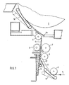
zeigt schematisch eine erfindungsgemäße Vorrichtung in Seitenansicht. - Bei der in Fig. 1 ausschnittsweise gezeigten Rollmaschine erfolgt die Zuführung der Materialbahn 1 - eine Papierbahn - von unten an eine als Saugwalze ausgebildete Stützwalze 2. Zur Papierbahnführung dienen drei Leitwalzen 3, 4, 5. Die von einer nicht dargestellten Abrollung in etwa waagerecht ankommende Bahn 1 wird von der Leitwalze 3 nach oben, von der Leitwalze 4 in die senkrechte und von der Leitwalze 5 tangential an die Stützwalze 2 gelenkt.
- Im Bereich der senkrechten Bahnführung zwischen den Leitwalzen 4 und 5 befindet sich eine Längsschneideeinrichtung mit mehreren, auf einer Parallelen zur Stützwalzenachse angeordneten Kreismesserpaaren. Die aus Obermesser 6 und Untermesser 7 bestehenden Kreismesserpaare dienen zum Aufteilen der Bahn 1 in Einzelbahnen, wobei die Obermesser 6 mit kurzem Hub von den Untermessern 7 wegbewegbar sind.
- Zum automatischen Heranführen eines neuen Bahnanfangs an die Stützwalze 2 dienen folgende zusätzlichen Elemente:
- Eine an den Umfang der Leitwalze 3 anschwenkbare Bänderschwinge 8 und ein fluchtend sich daran anschließendes Blech 9 lenken den Bahnanfang in Richtung der Leitwalze 4. Mit kurzem Abstand neben der Leitwalze 4 ist ein mittels einer pneumatischen Kolben-Zylinder-Einheit 10 vertikal beweglicher, sich senkrecht über einen Teil der Arbeitsbreite erstreckendes Leitblech angeordnet, das in hochgefahrener Position von der Leitwalze 4 durch die Messer 6, 7 bis zur Leitwalze 5 reicht. In niedergefahrener Position befindet sich die Oberkante des Leitblechs 11 etwa in Höhe der Leitwalze 4. Im vorliegenden Ausführungsbeispiel ist das - quer zur Laufrichtung - zentral angeordnete Leitblech 11 ca. 500 mm breit, um einen Bahnanfang von ca. 300 - 400 mm Breite zu führen.
- Im Bereich zwischen Leitblech 11 und Blech 9 sind mit regelmäßigem Abstand voneinander über die Breite des Leitblechs 11 Flachstrahldüsen 12 angeordnet, die aus einer nicht dargestellten Druckluftversorgung gespeist werden. Die etwa 50 mm breiten Flachstrahldüsen 12 weisen jeweils mehrere, nebeneinander angeordnete Ausblasöffnungen mit ca. 1 mm Durchmesser auf, aus denen die Druckluft in laminarer Strömung austritt. Der prinzipielle Aufbau derartiger Flachstrahldüsen ist in der DE-PS 24 13 614 beschrieben. Die Anordnung der Flachstrahldüsen 12, und damit die Strömungsrichtung der Druckluft, ist für den Transport der Bahn 1 senkrecht nach oben von entscheidender Bedeutung: Dazu sind die Flachstrahldüsen 12 - im vorliegenden Beispiel sind es drei - parallel zum Leitblech 11 und in sehr geringem Abstand zu diesem angeordnet. Es hat sich gezeigt, daß der Abstand der Ausblasöffnungen vom Leitblech 11 geringer als 10 mm sein muß, vorzugsweise beträgt er zwischen 0,5 und 1 mm.
- Am oberen Ende des senkrechten Teils der Förderstrecke im Bereich der Leitwalze 5 lenkt eine weitere Düse 13 den Bahnanfang in tangentialer Richtung zur Stützwalze 2. Für eine sichere Anlage des Bahnanfangs an die Stützwalze 2 ist an dieser Seite eine an die Stützwalze 2 anlegbare Bänderschwinge 14 angeordnet.
- Während des Aufwickelns der durch die Längsschneide-einrichtung 6, 7 erzeugten Einzelbahnen auf Wickelrollen, die sich auf dem oberen Teil der Stützwalze 2 abstützen, befinden sich die Elemente zur Einführung eines neuen Bahnanfangs in Ruhestellung, so daß sie die Bahnführung und damit den Wickelvorgang nicht behindern:
- Die Bänderschwingen 8, 14 sind von den jeweiligen Walzen, 3, 2 weggeschwenkt, das Leitblech 11 steht in unterster Position außerhalb der Längsschneideeinrichtung 6, 7 so daß das Obermesser 6 in Arbeitsstellung am Untermesser 7 anliegt, und die Düsen 12, 13 sind außer Betrieb.
- Zum Heranführen eines neuen Bahnanfangs, z.B. bei einer neuen Vorratsrolle in der Abrollung, werden zunächst die Messer 6, 7 auseinandergefahren, damit anschließend das Leitblech 11 in seine obere Position bewegt werden kann. Es erstreckt sich in dieser Position entlang der gesamten Strecke, auf der der neue Bahnanfang senkrecht geführt werden muß. Zusätzlich werden die Bänderschwingen 8, 14 an die Walzen 3, 12 angelegt, und die Düsen 12, 13 werden mit Druckluft gespeist.
- Im Bereich der Abrollung wird die Breite des einzuführenden Bahnanfangs durch Abreißen an den Rändern auf ca. 300 - 400 mm verringert. Die Länge des geschmälerten Bahnanfangs entspricht in etwa der Förderstrecke Leitwalze 3 - Stützwalze 2, im vorliegenden Beispiel ca. 1500 mm. Der neue Bahnanfang wird anschließend mit nicht dargestellten Förderbändern von der Abrollung zu der Leitwalze 3 geführt, wo er von der anliegenden Bänderschwinge 8 nach oben, über das Blech 9 in den Bereich der Luftströmung der Flachstrahldüsen 12 umgelenkt wird.
- Aufgrund ihres kurzen Abstandes vom Leitblech 11 blasen die Flachstrahldüsen 12 Druckluft in einer laminaren Strömung entlang der Oberfläche des Leitbleches 11 senkrecht nach oben. Aufgrund der - gegenüber der Transportgeschwindigkeit des Bahnanfangs - erhöhten Strömungsgeschwindigkeit entsteht zwischen dem Leitblech 11 und der Bahn 1 ein Unterdruck, der die Bahn 1 unmittelbar am Leitblech 11 führt. Zusätzlich bildet sich aufgrund der Rauheit der Papieroberfläche eine auf die Bahn wirkende, senkrecht nach oben weisende Kraftkomponente, die die Bahn 1 im Zusammenwirken mit den nachschiebenden Förderbändern nach oben transportiert.
- Wenn der Bahnanfang den Bereich der Leitwalze 5 erreicht hat, wird er von der aus der Düse 13 ausströmenden Druckluft in Richtung zur Bänderschwinge 14 umgelenkt und legt sich mit deren Hilfe an der Stützwalze 2 an. Sobald der an der Stützwalze anliegende, von dieser durch Ansaugen gehaltene Bahnanfang ausreichend groß ist, werden die Bänderschwingen 8, 14 wieder abgeschwenkt, das Leitblech 11 wird in seine untere Position gefahren, und die Messer 6, 7 werden in Arbeitsstellung bewegt. Nachdem die neuen Bahnanfänge der Einzelbahnen an Wickelhülsen befestigt wurden, kann die Rollmaschine auf ihre maximale Wickelgeschwindigkeit beschleunigt werden.
Claims (5)
bei dem der Bahnanfang mittels Druckluft an einem senkrechten, plattenförmigen Bahnführungselement nach oben bewegt wird, dadurch gekennzeichnet, daß die Druckluft in einer im wesentlichen laminaren Strömung entlang der Oberfläche eines Leitbleches und im wesentlichen parallel zu dieser nach oben geblasen wird.
Priority Applications (1)
| Application Number | Priority Date | Filing Date | Title |
|---|---|---|---|
| AT89108464T ATE86585T1 (de) | 1988-06-21 | 1989-05-11 | Vefahren und vorrichtung zum heranfuehren des anfanges einer materialbahn, insbesondere einer papierbahn, von unten an eine rollmaschinenwalze. |
Applications Claiming Priority (2)
| Application Number | Priority Date | Filing Date | Title |
|---|---|---|---|
| DE3820846 | 1988-06-21 | ||
| DE3820846A DE3820846A1 (de) | 1988-06-21 | 1988-06-21 | Verfahren und vorrichtung zum heranfuehren des anfanges einer materialbahn, insbesondere einer papierbahn, von unten an eine rollmaschinenwalze |
Publications (3)
| Publication Number | Publication Date |
|---|---|
| EP0347573A2 true EP0347573A2 (de) | 1989-12-27 |
| EP0347573A3 EP0347573A3 (en) | 1990-11-07 |
| EP0347573B1 EP0347573B1 (de) | 1993-03-10 |
Family
ID=6356879
Family Applications (1)
| Application Number | Title | Priority Date | Filing Date |
|---|---|---|---|
| EP89108464A Expired - Lifetime EP0347573B1 (de) | 1988-06-21 | 1989-05-11 | Vefahren und Vorrichtung zum Heranführen des Anfanges einer Materialbahn, insbesondere einer Papierbahn, von unten an eine Rollmaschinenwalze |
Country Status (8)
| Country | Link |
|---|---|
| US (1) | US5328136A (de) |
| EP (1) | EP0347573B1 (de) |
| JP (1) | JPH0243153A (de) |
| AT (1) | ATE86585T1 (de) |
| CA (1) | CA1333917C (de) |
| DE (2) | DE3820846A1 (de) |
| ES (1) | ES2039745T3 (de) |
| FI (1) | FI95684C (de) |
Cited By (4)
| Publication number | Priority date | Publication date | Assignee | Title |
|---|---|---|---|---|
| EP0741103A3 (de) * | 1995-05-05 | 1997-10-15 | Wifag Maschf | Vorrichtung zum Überführen eines Bahnanfangs einer Materialbahn in einer Rollenrotationsmaschine |
| WO1999028227A1 (en) * | 1997-12-01 | 1999-06-10 | Valmet Corporation | Change device of a reel-up and method for changing a roll |
| DE10338781A1 (de) * | 2003-08-23 | 2005-03-17 | Voith Paper Patent Gmbh | Verfahren und Vorrichtung zum Überführen einer Materialbahn |
| IT202100014702A1 (it) * | 2021-06-07 | 2022-12-07 | A Celli Paper Spa | Svolgitore per materiale nastriforme con sistemi per ridurre il vuoto dinamico durante lo svolgimento e metodo |
Families Citing this family (14)
| Publication number | Priority date | Publication date | Assignee | Title |
|---|---|---|---|---|
| DE3820846A1 (de) * | 1988-06-21 | 1989-12-28 | Jagenberg Ag | Verfahren und vorrichtung zum heranfuehren des anfanges einer materialbahn, insbesondere einer papierbahn, von unten an eine rollmaschinenwalze |
| DE3933861A1 (de) * | 1989-10-11 | 1991-04-18 | Jagenberg Ag | Verfahren und vorrichtung zum einfuehren einer materialbahn in eine verarbeitungsmaschine |
| DE4018883C1 (de) * | 1990-06-13 | 1991-10-10 | J.M. Voith Gmbh, 7920 Heidenheim, De | |
| DE4029914A1 (de) * | 1990-09-21 | 1992-03-26 | Jagenberg Ag | Tragwalzen-wickelmaschine |
| US5318237A (en) * | 1992-10-08 | 1994-06-07 | Fmc Corporation | Air horn for web winding machine |
| DE9414449U1 (de) * | 1994-09-06 | 1996-01-11 | Beloit Technologies, Inc., Wilmington, Del. | Wickelmaschine |
| DE19848812A1 (de) * | 1998-10-22 | 2000-04-27 | Voith Sulzer Papiertech Patent | Vorrichtung und Verfahren zum Aufführen einer Materialbahn |
| DE10137252A1 (de) * | 2001-07-31 | 2003-02-13 | Voith Paper Patent Gmbh | Verfahren zum Aufwickeln einer laufenden Materialbahn sowie Wickelmaschine zur Durchführung des Verfahrens |
| US20110240706A1 (en) * | 2010-03-30 | 2011-10-06 | Brian Christopher Schwamberger | Web diverting apparatus |
| CN102730454B (zh) * | 2012-06-29 | 2014-08-27 | 上海纺印印刷包装有限公司 | 一种分切边料的回收设备 |
| US10071871B2 (en) * | 2013-03-14 | 2018-09-11 | Gpcp Ip Holdings Llc | Air knife configured to improve rolling of paper product |
| US10040583B2 (en) * | 2015-07-23 | 2018-08-07 | Perpetual Machine Company | Carpet wrapping apparatus and method of using same |
| CN111703932B (zh) * | 2020-06-12 | 2022-09-13 | 石狮梵源服饰有限公司 | 一种加工用复卷边线头剪切机械 |
| DE102022113463A1 (de) * | 2022-05-27 | 2023-11-30 | Sprick Gmbh Bielefelder Papier- Und Wellpappenwerke & Co. | System zum umwandeln eines bahnförmigen ausgangsmaterials in verpackungstaschen |
Family Cites Families (5)
| Publication number | Priority date | Publication date | Assignee | Title |
|---|---|---|---|---|
| CA983063A (en) * | 1973-05-03 | 1976-02-03 | Reed International Limited | Web feeding apparatus |
| DE2413614C3 (de) * | 1974-03-21 | 1978-08-10 | Elring Dichtungswerke Kg, 7417 Dettingen | Mehrkanal-Düse zum Werkstücktransport von Kleinteilen |
| DE3102894C2 (de) * | 1981-01-29 | 1983-01-20 | Jagenberg-Werke AG, 4000 Düsseldorf | Vorrichtung zum getrennten Aufwickeln längsgeteilter Bahnen |
| DE3117094A1 (de) * | 1981-04-30 | 1982-11-18 | Jagenberg-Werke AG, 4000 Düsseldorf | Bahneinfuehrungsvorrichtung an wickelmaschinen |
| DE3820846A1 (de) * | 1988-06-21 | 1989-12-28 | Jagenberg Ag | Verfahren und vorrichtung zum heranfuehren des anfanges einer materialbahn, insbesondere einer papierbahn, von unten an eine rollmaschinenwalze |
-
1988
- 1988-06-21 DE DE3820846A patent/DE3820846A1/de active Granted
-
1989
- 1989-05-11 EP EP89108464A patent/EP0347573B1/de not_active Expired - Lifetime
- 1989-05-11 ES ES198989108464T patent/ES2039745T3/es not_active Expired - Lifetime
- 1989-05-11 AT AT89108464T patent/ATE86585T1/de not_active IP Right Cessation
- 1989-05-11 DE DE8989108464T patent/DE58903696D1/de not_active Expired - Lifetime
- 1989-06-20 CA CA000603278A patent/CA1333917C/en not_active Expired - Fee Related
- 1989-06-20 FI FI893015A patent/FI95684C/fi active IP Right Grant
- 1989-06-21 JP JP1156952A patent/JPH0243153A/ja active Pending
-
1991
- 1991-04-25 US US07/692,807 patent/US5328136A/en not_active Expired - Lifetime
Cited By (5)
| Publication number | Priority date | Publication date | Assignee | Title |
|---|---|---|---|---|
| EP0741103A3 (de) * | 1995-05-05 | 1997-10-15 | Wifag Maschf | Vorrichtung zum Überführen eines Bahnanfangs einer Materialbahn in einer Rollenrotationsmaschine |
| WO1999028227A1 (en) * | 1997-12-01 | 1999-06-10 | Valmet Corporation | Change device of a reel-up and method for changing a roll |
| DE10338781A1 (de) * | 2003-08-23 | 2005-03-17 | Voith Paper Patent Gmbh | Verfahren und Vorrichtung zum Überführen einer Materialbahn |
| IT202100014702A1 (it) * | 2021-06-07 | 2022-12-07 | A Celli Paper Spa | Svolgitore per materiale nastriforme con sistemi per ridurre il vuoto dinamico durante lo svolgimento e metodo |
| WO2022258504A1 (en) * | 2021-06-07 | 2022-12-15 | A.Celli Paper S.P.A. | Unwinder for web material, provided with systems for reducing dynamic vacuum during unwinding, and related method |
Also Published As
| Publication number | Publication date |
|---|---|
| FI893015A0 (fi) | 1989-06-20 |
| JPH0243153A (ja) | 1990-02-13 |
| EP0347573A3 (en) | 1990-11-07 |
| ATE86585T1 (de) | 1993-03-15 |
| DE3820846A1 (de) | 1989-12-28 |
| FI95684B (fi) | 1995-11-30 |
| FI893015A7 (fi) | 1989-12-22 |
| FI95684C (fi) | 1996-03-11 |
| US5328136A (en) | 1994-07-12 |
| EP0347573B1 (de) | 1993-03-10 |
| CA1333917C (en) | 1995-01-10 |
| DE58903696D1 (de) | 1993-04-15 |
| DE3820846C2 (de) | 1990-03-29 |
| ES2039745T3 (es) | 1993-10-01 |
Similar Documents
| Publication | Publication Date | Title |
|---|---|---|
| EP0347573B1 (de) | Vefahren und Vorrichtung zum Heranführen des Anfanges einer Materialbahn, insbesondere einer Papierbahn, von unten an eine Rollmaschinenwalze | |
| EP1245729B1 (de) | Vorrichtung zum Überführen einer Bahn | |
| EP0252418B1 (de) | Planschneidemaschine | |
| DE19723749A1 (de) | Verfahren und Vorrichtung zum Quertrennen von laufenden Bedruckstoffbahnen | |
| DE2600718B2 (de) | Vorrichtung zum Unterteilen von Flachmaterialbahnen in Längsstreifen von gewünschter Breite | |
| DE4334394A1 (de) | Luftblasstutzen für Bahnaufwickelmaschinen | |
| EP0288814A1 (de) | Vorrichtung zum Unterteilen einer endlosen Papierbahn mit Zickzackfalzung | |
| DE2238370A1 (de) | Einrichtung und verfahren zum richten eines metallbandes | |
| CH680363A5 (de) | ||
| DE2909736B2 (de) | Verfahren und Doppeltragwalzenroller zum Aufrollen von endlos zugeführten Bahnen | |
| DE69601056T2 (de) | In Abschnitte unterteilte Tänzerwalze und Fördermechanismus für bahnförmiges Material | |
| EP0697989B1 (de) | Vorrichtung zum schuppen und ablegen von bogen auf einen stapel | |
| DE19729530C2 (de) | Rollenschneider | |
| DE4408713A1 (de) | Verfahren und Vorrichtung zum Führen einer Materialbahn | |
| EP0461495B1 (de) | Vorrichtung zum Heranführen des Anfangs einer Papierbahn von unten her an eine Rollenwalze | |
| DE3125553C2 (de) | Querschneidvorrichtung | |
| DE3901854A1 (de) | Vorrichtung zum verbinden von materialbahnen | |
| DE3933861A1 (de) | Verfahren und vorrichtung zum einfuehren einer materialbahn in eine verarbeitungsmaschine | |
| EP1970334A2 (de) | Bogen bearbeitende Maschine mit pneumatischer Transportvorrichtung | |
| EP0188452B1 (de) | Einrichtung zur herstellung von schnittschablonen | |
| DE4305579A1 (de) | Vorrichtung zum Ansammeln von Papierbogen | |
| EP1065313A2 (de) | Vorrichtung zum Trennen und Überführen eines Einführstreifens | |
| DE2407848C2 (de) | Vorrichtung zum Einebnen und ebenflächigen Weiterführen von einer oder mehreren in Papierverarbeitungsmaschinen freischwebend geführten Materialbahnen | |
| EP1200329B1 (de) | Verfahren und vorrichtung zum kürzen der fahne im anschluss an einen fliegenden rollenwechsel | |
| DD255710A1 (de) | Verfahren und vorrichtung zur stabilisierung von extrem duennem packmittel |
Legal Events
| Date | Code | Title | Description |
|---|---|---|---|
| PUAI | Public reference made under article 153(3) epc to a published international application that has entered the european phase |
Free format text: ORIGINAL CODE: 0009012 |
|
| AK | Designated contracting states |
Kind code of ref document: A2 Designated state(s): AT CH DE ES FR GB IT LI NL SE |
|
| PUAL | Search report despatched |
Free format text: ORIGINAL CODE: 0009013 |
|
| AK | Designated contracting states |
Kind code of ref document: A3 Designated state(s): AT CH DE ES FR GB IT LI NL SE |
|
| 17P | Request for examination filed |
Effective date: 19901012 |
|
| 17Q | First examination report despatched |
Effective date: 19920611 |
|
| GRAA | (expected) grant |
Free format text: ORIGINAL CODE: 0009210 |
|
| ITF | It: translation for a ep patent filed | ||
| AK | Designated contracting states |
Kind code of ref document: B1 Designated state(s): AT CH DE ES FR GB IT LI NL SE |
|
| PG25 | Lapsed in a contracting state [announced via postgrant information from national office to epo] |
Ref country code: NL Effective date: 19930310 |
|
| REF | Corresponds to: |
Ref document number: 86585 Country of ref document: AT Date of ref document: 19930315 Kind code of ref document: T |
|
| REF | Corresponds to: |
Ref document number: 58903696 Country of ref document: DE Date of ref document: 19930415 |
|
| GBT | Gb: translation of ep patent filed (gb section 77(6)(a)/1977) |
Effective date: 19930324 |
|
| ET | Fr: translation filed | ||
| PG25 | Lapsed in a contracting state [announced via postgrant information from national office to epo] |
Ref country code: LI Effective date: 19930531 Ref country code: CH Effective date: 19930531 |
|
| NLV1 | Nl: lapsed or annulled due to failure to fulfill the requirements of art. 29p and 29m of the patents act | ||
| REG | Reference to a national code |
Ref country code: ES Ref legal event code: FG2A Ref document number: 2039745 Country of ref document: ES Kind code of ref document: T3 |
|
| PLBE | No opposition filed within time limit |
Free format text: ORIGINAL CODE: 0009261 |
|
| STAA | Information on the status of an ep patent application or granted ep patent |
Free format text: STATUS: NO OPPOSITION FILED WITHIN TIME LIMIT |
|
| REG | Reference to a national code |
Ref country code: CH Ref legal event code: PL |
|
| 26N | No opposition filed | ||
| EAL | Se: european patent in force in sweden |
Ref document number: 89108464.2 |
|
| REG | Reference to a national code |
Ref country code: GB Ref legal event code: IF02 |
|
| PGFP | Annual fee paid to national office [announced via postgrant information from national office to epo] |
Ref country code: GB Payment date: 20030422 Year of fee payment: 15 |
|
| PGFP | Annual fee paid to national office [announced via postgrant information from national office to epo] |
Ref country code: FR Payment date: 20030522 Year of fee payment: 15 |
|
| PGFP | Annual fee paid to national office [announced via postgrant information from national office to epo] |
Ref country code: AT Payment date: 20030523 Year of fee payment: 15 |
|
| PG25 | Lapsed in a contracting state [announced via postgrant information from national office to epo] |
Ref country code: AT Free format text: LAPSE BECAUSE OF NON-PAYMENT OF DUE FEES Effective date: 20040511 Ref country code: GB Free format text: LAPSE BECAUSE OF NON-PAYMENT OF DUE FEES Effective date: 20040511 |
|
| GBPC | Gb: european patent ceased through non-payment of renewal fee |
Effective date: 20040511 |
|
| PG25 | Lapsed in a contracting state [announced via postgrant information from national office to epo] |
Ref country code: FR Free format text: LAPSE BECAUSE OF NON-PAYMENT OF DUE FEES Effective date: 20050131 |
|
| REG | Reference to a national code |
Ref country code: FR Ref legal event code: ST |
|
| PG25 | Lapsed in a contracting state [announced via postgrant information from national office to epo] |
Ref country code: IT Free format text: LAPSE BECAUSE OF NON-PAYMENT OF DUE FEES;WARNING: LAPSES OF ITALIAN PATENTS WITH EFFECTIVE DATE BEFORE 2007 MAY HAVE OCCURRED AT ANY TIME BEFORE 2007. THE CORRECT EFFECTIVE DATE MAY BE DIFFERENT FROM THE ONE RECORDED. Effective date: 20050511 |
|
| PGFP | Annual fee paid to national office [announced via postgrant information from national office to epo] |
Ref country code: SE Payment date: 20050512 Year of fee payment: 17 |
|
| PGFP | Annual fee paid to national office [announced via postgrant information from national office to epo] |
Ref country code: ES Payment date: 20050513 Year of fee payment: 17 |
|
| PG25 | Lapsed in a contracting state [announced via postgrant information from national office to epo] |
Ref country code: ES Free format text: LAPSE BECAUSE OF NON-PAYMENT OF DUE FEES Effective date: 20060512 Ref country code: SE Free format text: LAPSE BECAUSE OF NON-PAYMENT OF DUE FEES Effective date: 20060512 |
|
| EUG | Se: european patent has lapsed | ||
| REG | Reference to a national code |
Ref country code: ES Ref legal event code: FD2A Effective date: 20060512 |
|
| REG | Reference to a national code |
Ref country code: FR Ref legal event code: TP |
|
| PGFP | Annual fee paid to national office [announced via postgrant information from national office to epo] |
Ref country code: DE Payment date: 20080523 Year of fee payment: 20 |