EP0346911B1 - Anzeigemedium, Anzeigeverfahren und -vorrichtung - Google Patents
Anzeigemedium, Anzeigeverfahren und -vorrichtung Download PDFInfo
- Publication number
- EP0346911B1 EP0346911B1 EP89110908A EP89110908A EP0346911B1 EP 0346911 B1 EP0346911 B1 EP 0346911B1 EP 89110908 A EP89110908 A EP 89110908A EP 89110908 A EP89110908 A EP 89110908A EP 0346911 B1 EP0346911 B1 EP 0346911B1
- Authority
- EP
- European Patent Office
- Prior art keywords
- display
- layer
- liquid crystal
- temperature
- layers
- Prior art date
- Legal status (The legal status is an assumption and is not a legal conclusion. Google has not performed a legal analysis and makes no representation as to the accuracy of the status listed.)
- Expired - Lifetime
Links
- 238000000034 method Methods 0.000 title claims description 27
- 239000005264 High molar mass liquid crystal Substances 0.000 claims description 75
- 239000004973 liquid crystal related substance Substances 0.000 claims description 34
- 230000009477 glass transition Effects 0.000 claims description 28
- 239000004990 Smectic liquid crystal Substances 0.000 claims description 18
- 230000003287 optical effect Effects 0.000 claims description 18
- 230000007704 transition Effects 0.000 claims description 15
- 239000011295 pitch Substances 0.000 claims description 10
- 238000000149 argon plasma sintering Methods 0.000 claims description 9
- 239000000203 mixture Substances 0.000 claims description 8
- 239000010410 layer Substances 0.000 description 206
- 229920000642 polymer Polymers 0.000 description 77
- 239000000758 substrate Substances 0.000 description 26
- 238000001816 cooling Methods 0.000 description 19
- 238000010438 heat treatment Methods 0.000 description 15
- 230000000694 effects Effects 0.000 description 12
- 239000003086 colorant Substances 0.000 description 10
- 238000011282 treatment Methods 0.000 description 10
- 229920001721 polyimide Polymers 0.000 description 9
- 230000003098 cholesteric effect Effects 0.000 description 7
- -1 p-terephthalic acid Chemical compound 0.000 description 7
- 239000000243 solution Substances 0.000 description 7
- SCYULBFZEHDVBN-UHFFFAOYSA-N 1,1-Dichloroethane Chemical compound CC(Cl)Cl SCYULBFZEHDVBN-UHFFFAOYSA-N 0.000 description 6
- 239000004642 Polyimide Substances 0.000 description 6
- 150000001875 compounds Chemical class 0.000 description 6
- 238000009826 distribution Methods 0.000 description 6
- LIVNPJMFVYWSIS-UHFFFAOYSA-N silicon monoxide Chemical compound [Si-]#[O+] LIVNPJMFVYWSIS-UHFFFAOYSA-N 0.000 description 6
- 238000007740 vapor deposition Methods 0.000 description 6
- 239000004372 Polyvinyl alcohol Substances 0.000 description 5
- 239000006096 absorbing agent Substances 0.000 description 5
- 230000008859 change Effects 0.000 description 5
- 239000011248 coating agent Substances 0.000 description 5
- 238000000576 coating method Methods 0.000 description 5
- 229920002451 polyvinyl alcohol Polymers 0.000 description 5
- 239000011241 protective layer Substances 0.000 description 5
- 229920005989 resin Polymers 0.000 description 5
- 239000011347 resin Substances 0.000 description 5
- 238000002834 transmittance Methods 0.000 description 5
- 239000004793 Polystyrene Substances 0.000 description 4
- VYPSYNLAJGMNEJ-UHFFFAOYSA-N Silicium dioxide Chemical compound O=[Si]=O VYPSYNLAJGMNEJ-UHFFFAOYSA-N 0.000 description 4
- MCMNRKCIXSYSNV-UHFFFAOYSA-N Zirconium dioxide Chemical compound O=[Zr]=O MCMNRKCIXSYSNV-UHFFFAOYSA-N 0.000 description 4
- 239000002253 acid Substances 0.000 description 4
- 230000015572 biosynthetic process Effects 0.000 description 4
- 238000010586 diagram Methods 0.000 description 4
- 238000001035 drying Methods 0.000 description 4
- 230000005684 electric field Effects 0.000 description 4
- 238000005227 gel permeation chromatography Methods 0.000 description 4
- 239000011521 glass Substances 0.000 description 4
- 229920000728 polyester Polymers 0.000 description 4
- 229920002223 polystyrene Polymers 0.000 description 4
- 230000000717 retained effect Effects 0.000 description 4
- 239000000126 substance Substances 0.000 description 4
- 239000004986 Cholesteric liquid crystals (ChLC) Substances 0.000 description 3
- LYCAIKOWRPUZTN-UHFFFAOYSA-N Ethylene glycol Chemical compound OCCO LYCAIKOWRPUZTN-UHFFFAOYSA-N 0.000 description 3
- 229920000106 Liquid crystal polymer Polymers 0.000 description 3
- 229910052799 carbon Inorganic materials 0.000 description 3
- 230000003247 decreasing effect Effects 0.000 description 3
- MTHSVFCYNBDYFN-UHFFFAOYSA-N diethylene glycol Chemical compound OCCOCCO MTHSVFCYNBDYFN-UHFFFAOYSA-N 0.000 description 3
- 230000006870 function Effects 0.000 description 3
- 238000010008 shearing Methods 0.000 description 3
- 0 *Oc(cc1)ccc1C(O)=O Chemical compound *Oc(cc1)ccc1C(O)=O 0.000 description 2
- SYEOWUNSTUDKGM-UHFFFAOYSA-N 3-methyladipic acid Chemical compound OC(=O)CC(C)CCC(O)=O SYEOWUNSTUDKGM-UHFFFAOYSA-N 0.000 description 2
- SQAJRDHPLTWZQT-UHFFFAOYSA-N 3-methylhexane-1,6-diol Chemical compound OCCC(C)CCCO SQAJRDHPLTWZQT-UHFFFAOYSA-N 0.000 description 2
- 229920000178 Acrylic resin Polymers 0.000 description 2
- 239000004925 Acrylic resin Substances 0.000 description 2
- 229910052582 BN Inorganic materials 0.000 description 2
- PZNSFCLAULLKQX-UHFFFAOYSA-N Boron nitride Chemical compound N#B PZNSFCLAULLKQX-UHFFFAOYSA-N 0.000 description 2
- YCKRFDGAMUMZLT-UHFFFAOYSA-N Fluorine atom Chemical compound [F] YCKRFDGAMUMZLT-UHFFFAOYSA-N 0.000 description 2
- QIGBRXMKCJKVMJ-UHFFFAOYSA-N Hydroquinone Chemical compound OC1=CC=C(O)C=C1 QIGBRXMKCJKVMJ-UHFFFAOYSA-N 0.000 description 2
- JVTAAEKCZFNVCJ-REOHCLBHSA-N L-lactic acid Chemical compound C[C@H](O)C(O)=O JVTAAEKCZFNVCJ-REOHCLBHSA-N 0.000 description 2
- OFOBLEOULBTSOW-UHFFFAOYSA-N Malonic acid Chemical compound OC(=O)CC(O)=O OFOBLEOULBTSOW-UHFFFAOYSA-N 0.000 description 2
- 239000004962 Polyamide-imide Substances 0.000 description 2
- 229910052581 Si3N4 Inorganic materials 0.000 description 2
- DHKHKXVYLBGOIT-UHFFFAOYSA-N acetaldehyde Diethyl Acetal Natural products CCOC(C)OCC DHKHKXVYLBGOIT-UHFFFAOYSA-N 0.000 description 2
- 150000001241 acetals Chemical class 0.000 description 2
- 230000009471 action Effects 0.000 description 2
- WNLRTRBMVRJNCN-UHFFFAOYSA-N adipic acid Chemical compound OC(=O)CCCCC(O)=O WNLRTRBMVRJNCN-UHFFFAOYSA-N 0.000 description 2
- 150000001721 carbon Chemical group 0.000 description 2
- 230000015556 catabolic process Effects 0.000 description 2
- 239000003054 catalyst Substances 0.000 description 2
- 229910000420 cerium oxide Inorganic materials 0.000 description 2
- QCCDYNYSHILRDG-UHFFFAOYSA-K cerium(3+);trifluoride Chemical compound [F-].[F-].[F-].[Ce+3] QCCDYNYSHILRDG-UHFFFAOYSA-K 0.000 description 2
- 238000006731 degradation reaction Methods 0.000 description 2
- 150000001991 dicarboxylic acids Chemical class 0.000 description 2
- 150000002009 diols Chemical class 0.000 description 2
- ZUOUZKKEUPVFJK-UHFFFAOYSA-N diphenyl Chemical compound C1=CC=CC=C1C1=CC=CC=C1 ZUOUZKKEUPVFJK-UHFFFAOYSA-N 0.000 description 2
- 239000011737 fluorine Substances 0.000 description 2
- 229910052731 fluorine Inorganic materials 0.000 description 2
- 229910052736 halogen Inorganic materials 0.000 description 2
- 150000002367 halogens Chemical class 0.000 description 2
- 230000031700 light absorption Effects 0.000 description 2
- 239000007788 liquid Substances 0.000 description 2
- 239000000463 material Substances 0.000 description 2
- 229910052751 metal Inorganic materials 0.000 description 2
- 239000002184 metal Substances 0.000 description 2
- CKFGINPQOCXMAZ-UHFFFAOYSA-N methanediol Chemical compound OCO CKFGINPQOCXMAZ-UHFFFAOYSA-N 0.000 description 2
- BDJRBEYXGGNYIS-UHFFFAOYSA-N nonanedioic acid Chemical compound OC(=O)CCCCCCCC(O)=O BDJRBEYXGGNYIS-UHFFFAOYSA-N 0.000 description 2
- WLJVNTCWHIRURA-UHFFFAOYSA-N pimelic acid Chemical compound OC(=O)CCCCCC(O)=O WLJVNTCWHIRURA-UHFFFAOYSA-N 0.000 description 2
- 229920003055 poly(ester-imide) Polymers 0.000 description 2
- 229920000052 poly(p-xylylene) Polymers 0.000 description 2
- 229920002312 polyamide-imide Polymers 0.000 description 2
- 229920000515 polycarbonate Polymers 0.000 description 2
- 239000004417 polycarbonate Substances 0.000 description 2
- 238000006068 polycondensation reaction Methods 0.000 description 2
- 239000004810 polytetrafluoroethylene Substances 0.000 description 2
- 229920001343 polytetrafluoroethylene Polymers 0.000 description 2
- CXMXRPHRNRROMY-UHFFFAOYSA-N sebacic acid Chemical compound OC(=O)CCCCCCCCC(O)=O CXMXRPHRNRROMY-UHFFFAOYSA-N 0.000 description 2
- 239000000377 silicon dioxide Substances 0.000 description 2
- 235000012239 silicon dioxide Nutrition 0.000 description 2
- HQVNEWCFYHHQES-UHFFFAOYSA-N silicon nitride Chemical compound N12[Si]34N5[Si]62N3[Si]51N64 HQVNEWCFYHHQES-UHFFFAOYSA-N 0.000 description 2
- 239000002904 solvent Substances 0.000 description 2
- TYFQFVWCELRYAO-UHFFFAOYSA-N suberic acid Chemical compound OC(=O)CCCCCCC(O)=O TYFQFVWCELRYAO-UHFFFAOYSA-N 0.000 description 2
- 229920002554 vinyl polymer Polymers 0.000 description 2
- ZGCUJZRGGAOOLD-UHFFFAOYSA-N (2,3-dihydroxyphenyl)imino-oxido-phenylazanium Chemical compound OC=1C(=C(C=CC1)N=[N+]([O-])C1=CC=CC=C1)O ZGCUJZRGGAOOLD-UHFFFAOYSA-N 0.000 description 1
- LCZVSXRMYJUNFX-CIUDSAMLSA-N (2s)-2-[(2s)-2-[(2s)-2-hydroxypropoxy]propoxy]propan-1-ol Chemical compound C[C@H](O)CO[C@@H](C)CO[C@@H](C)CO LCZVSXRMYJUNFX-CIUDSAMLSA-N 0.000 description 1
- DUFKCOQISQKSAV-WDSKDSINSA-N (2s)-2-[(2s)-2-hydroxypropoxy]propan-1-ol Chemical compound C[C@H](O)CO[C@@H](C)CO DUFKCOQISQKSAV-WDSKDSINSA-N 0.000 description 1
- DNIAPMSPPWPWGF-GSVOUGTGSA-N (R)-(-)-Propylene glycol Chemical compound C[C@@H](O)CO DNIAPMSPPWPWGF-GSVOUGTGSA-N 0.000 description 1
- OFUIFLZWMQEMFY-UHFFFAOYSA-N 1,2-dihydropyridazine-3,4-dione Chemical compound O=C1C=CNNC1=O OFUIFLZWMQEMFY-UHFFFAOYSA-N 0.000 description 1
- RTBFRGCFXZNCOE-UHFFFAOYSA-N 1-methylsulfonylpiperidin-4-one Chemical compound CS(=O)(=O)N1CCC(=O)CC1 RTBFRGCFXZNCOE-UHFFFAOYSA-N 0.000 description 1
- IIZPXYDJLKNOIY-JXPKJXOSSA-N 1-palmitoyl-2-arachidonoyl-sn-glycero-3-phosphocholine Chemical compound CCCCCCCCCCCCCCCC(=O)OC[C@H](COP([O-])(=O)OCC[N+](C)(C)C)OC(=O)CCC\C=C/C\C=C/C\C=C/C\C=C/CCCCC IIZPXYDJLKNOIY-JXPKJXOSSA-N 0.000 description 1
- PLYZRRVRRKNGRW-UHFFFAOYSA-N 2-(2-oxohydrazinyl)benzoic acid Chemical compound ON=NC1=CC=CC=C1C(O)=O PLYZRRVRRKNGRW-UHFFFAOYSA-N 0.000 description 1
- UVSDRKFNFKQZOD-UHFFFAOYSA-N 2-[1-(2-hydroxyphenoxy)ethoxy]phenol Chemical compound C=1C=CC=C(O)C=1OC(C)OC1=CC=CC=C1O UVSDRKFNFKQZOD-UHFFFAOYSA-N 0.000 description 1
- AKWFJQNBHYVIPY-UHFFFAOYSA-N 2-[2-[2-[2-[2-[2-[2-[2-[2-[2-[2-[2-(2-hydroxyethoxy)ethoxy]ethoxy]ethoxy]ethoxy]ethoxy]ethoxy]ethoxy]ethoxy]ethoxy]ethoxy]ethoxy]ethanol Chemical compound OCCOCCOCCOCCOCCOCCOCCOCCOCCOCCOCCOCCOCCO AKWFJQNBHYVIPY-UHFFFAOYSA-N 0.000 description 1
- KXTAOXNYQGASTA-UHFFFAOYSA-N 2-benzylidenepropanedioic acid Chemical compound OC(=O)C(C(O)=O)=CC1=CC=CC=C1 KXTAOXNYQGASTA-UHFFFAOYSA-N 0.000 description 1
- YZDMGNJPLDORQM-UHFFFAOYSA-N 2-hydroxy-6-(2-phenylethenyl)benzoic acid Chemical compound OC(=O)C1=C(O)C=CC=C1C=CC1=CC=CC=C1 YZDMGNJPLDORQM-UHFFFAOYSA-N 0.000 description 1
- CJMKSYKFEDJPMM-UHFFFAOYSA-N 2-hydroxy-6-phenylbenzoic acid Chemical compound OC(=O)C1=C(O)C=CC=C1C1=CC=CC=C1 CJMKSYKFEDJPMM-UHFFFAOYSA-N 0.000 description 1
- SJTKQIPAACOOGS-UHFFFAOYSA-N 3,3-dimethylbutane-1,2,4-triol Chemical compound OCC(C)(C)C(O)CO SJTKQIPAACOOGS-UHFFFAOYSA-N 0.000 description 1
- RMGZZGUIMNISKP-UHFFFAOYSA-N 3-(2,3-dihydroxyphenoxy)benzene-1,2-diol Chemical compound OC1=CC=CC(OC=2C(=C(O)C=CC=2)O)=C1O RMGZZGUIMNISKP-UHFFFAOYSA-N 0.000 description 1
- OONPLQJHBJXVBP-UHFFFAOYSA-N 3-(2-phenylethenyl)phthalic acid Chemical compound OC(=O)C1=CC=CC(C=CC=2C=CC=CC=2)=C1C(O)=O OONPLQJHBJXVBP-UHFFFAOYSA-N 0.000 description 1
- XHWWJYJRLKMVDZ-UHFFFAOYSA-N 3-(2-phenylphenyl)benzene-1,2-diol Chemical group OC1=CC=CC(C=2C(=CC=CC=2)C=2C=CC=CC=2)=C1O XHWWJYJRLKMVDZ-UHFFFAOYSA-N 0.000 description 1
- DAWHTISAONTGQE-UHFFFAOYSA-N 3-(2-phenylphenyl)phthalic acid Chemical compound OC(=O)C1=CC=CC(C=2C(=CC=CC=2)C=2C=CC=CC=2)=C1C(O)=O DAWHTISAONTGQE-UHFFFAOYSA-N 0.000 description 1
- WGKYSFRFMQHMOF-UHFFFAOYSA-N 3-bromo-5-methylpyridine-2-carbonitrile Chemical compound CC1=CN=C(C#N)C(Br)=C1 WGKYSFRFMQHMOF-UHFFFAOYSA-N 0.000 description 1
- HSSYVKMJJLDTKZ-UHFFFAOYSA-N 3-phenylphthalic acid Chemical compound OC(=O)C1=CC=CC(C=2C=CC=CC=2)=C1C(O)=O HSSYVKMJJLDTKZ-UHFFFAOYSA-N 0.000 description 1
- FJKROLUGYXJWQN-UHFFFAOYSA-N 4-hydroxybenzoic acid Chemical compound OC(=O)C1=CC=C(O)C=C1 FJKROLUGYXJWQN-UHFFFAOYSA-N 0.000 description 1
- 229930182843 D-Lactic acid Natural products 0.000 description 1
- FBPFZTCFMRRESA-KVTDHHQDSA-N D-Mannitol Chemical compound OC[C@@H](O)[C@@H](O)[C@H](O)[C@H](O)CO FBPFZTCFMRRESA-KVTDHHQDSA-N 0.000 description 1
- JVTAAEKCZFNVCJ-UWTATZPHSA-N D-lactic acid Chemical compound C[C@@H](O)C(O)=O JVTAAEKCZFNVCJ-UWTATZPHSA-N 0.000 description 1
- LFQSCWFLJHTTHZ-UHFFFAOYSA-N Ethanol Chemical compound CCO LFQSCWFLJHTTHZ-UHFFFAOYSA-N 0.000 description 1
- KRHYYFGTRYWZRS-UHFFFAOYSA-M Fluoride anion Chemical compound [F-] KRHYYFGTRYWZRS-UHFFFAOYSA-M 0.000 description 1
- WHUUTDBJXJRKMK-UHFFFAOYSA-N Glutamic acid Natural products OC(=O)C(N)CCC(O)=O WHUUTDBJXJRKMK-UHFFFAOYSA-N 0.000 description 1
- FBPFZTCFMRRESA-BXKVDMCESA-N L-mannitol Chemical compound OC[C@H](O)[C@H](O)[C@@H](O)[C@@H](O)CO FBPFZTCFMRRESA-BXKVDMCESA-N 0.000 description 1
- 239000004977 Liquid-crystal polymers (LCPs) Substances 0.000 description 1
- 229920000877 Melamine resin Polymers 0.000 description 1
- 239000004640 Melamine resin Substances 0.000 description 1
- CERQOIWHTDAKMF-UHFFFAOYSA-N Methacrylic acid Chemical compound CC(=C)C(O)=O CERQOIWHTDAKMF-UHFFFAOYSA-N 0.000 description 1
- RNSZTXYUIYQDBP-UHFFFAOYSA-N OC1=C(C(=CC=C1)C=1C(=CC=CC1)C1=CC=CC=C1)C(=O)O Chemical compound OC1=C(C(=CC=C1)C=1C(=CC=CC1)C1=CC=CC=C1)C(=O)O RNSZTXYUIYQDBP-UHFFFAOYSA-N 0.000 description 1
- BELSCVNBVPBHEO-UHFFFAOYSA-N OC=1C(=C(C(=C(C1)N=[N+]([O-])C1=CC=CC=C1)C)C)O Chemical compound OC=1C(=C(C(=C(C1)N=[N+]([O-])C1=CC=CC=C1)C)C)O BELSCVNBVPBHEO-UHFFFAOYSA-N 0.000 description 1
- AEFRZZBBXJWPCS-UHFFFAOYSA-N OC=1C(=C(C=CC1C)N=NC1=CC=C(C=C1)C)O Chemical compound OC=1C(=C(C=CC1C)N=NC1=CC=C(C=C1)C)O AEFRZZBBXJWPCS-UHFFFAOYSA-N 0.000 description 1
- ZFAHTWRWOFMODY-UHFFFAOYSA-N O[N+]([O-])=NC1=C(C=CC=C1)C(=O)O Chemical compound O[N+]([O-])=NC1=C(C=CC=C1)C(=O)O ZFAHTWRWOFMODY-UHFFFAOYSA-N 0.000 description 1
- 239000004952 Polyamide Substances 0.000 description 1
- DNIAPMSPPWPWGF-UHFFFAOYSA-N Propylene glycol Chemical compound CC(O)CO DNIAPMSPPWPWGF-UHFFFAOYSA-N 0.000 description 1
- BLRPTPMANUNPDV-UHFFFAOYSA-N Silane Chemical compound [SiH4] BLRPTPMANUNPDV-UHFFFAOYSA-N 0.000 description 1
- KDYFGRWQOYBRFD-UHFFFAOYSA-N Succinic acid Natural products OC(=O)CCC(O)=O KDYFGRWQOYBRFD-UHFFFAOYSA-N 0.000 description 1
- UWHCKJMYHZGTIT-UHFFFAOYSA-N Tetraethylene glycol, Natural products OCCOCCOCCOCCO UWHCKJMYHZGTIT-UHFFFAOYSA-N 0.000 description 1
- 241001296405 Tiso Species 0.000 description 1
- 229920001807 Urea-formaldehyde Polymers 0.000 description 1
- 239000001361 adipic acid Substances 0.000 description 1
- 235000011037 adipic acid Nutrition 0.000 description 1
- 229910052782 aluminium Inorganic materials 0.000 description 1
- VXAUWWUXCIMFIM-UHFFFAOYSA-M aluminum;oxygen(2-);hydroxide Chemical compound [OH-].[O-2].[Al+3] VXAUWWUXCIMFIM-UHFFFAOYSA-M 0.000 description 1
- JFCQEDHGNNZCLN-UHFFFAOYSA-N anhydrous glutaric acid Natural products OC(=O)CCCC(O)=O JFCQEDHGNNZCLN-UHFFFAOYSA-N 0.000 description 1
- 239000007864 aqueous solution Substances 0.000 description 1
- QVGXLLKOCUKJST-UHFFFAOYSA-N atomic oxygen Chemical compound [O] QVGXLLKOCUKJST-UHFFFAOYSA-N 0.000 description 1
- 235000010290 biphenyl Nutrition 0.000 description 1
- 239000004305 biphenyl Substances 0.000 description 1
- VCCBEIPGXKNHFW-UHFFFAOYSA-N biphenyl-4,4'-diol Chemical group C1=CC(O)=CC=C1C1=CC=C(O)C=C1 VCCBEIPGXKNHFW-UHFFFAOYSA-N 0.000 description 1
- KDYFGRWQOYBRFD-NUQCWPJISA-N butanedioic acid Chemical compound O[14C](=O)CC[14C](O)=O KDYFGRWQOYBRFD-NUQCWPJISA-N 0.000 description 1
- FAPWYRCQGJNNSJ-UBKPKTQASA-L calcium D-pantothenic acid Chemical compound [Ca+2].OCC(C)(C)[C@@H](O)C(=O)NCCC([O-])=O.OCC(C)(C)[C@@H](O)C(=O)NCCC([O-])=O FAPWYRCQGJNNSJ-UBKPKTQASA-L 0.000 description 1
- 229960002079 calcium pantothenate Drugs 0.000 description 1
- 239000006229 carbon black Substances 0.000 description 1
- BVKZGUZCCUSVTD-UHFFFAOYSA-N carbonic acid Chemical class OC(O)=O BVKZGUZCCUSVTD-UHFFFAOYSA-N 0.000 description 1
- 238000005266 casting Methods 0.000 description 1
- WKODVHZBYIBMOC-UHFFFAOYSA-N chembl116175 Chemical compound C1=CC(O)=CC=C1N=NC1=CC=C(O)C=C1 WKODVHZBYIBMOC-UHFFFAOYSA-N 0.000 description 1
- 239000003795 chemical substances by application Substances 0.000 description 1
- 229920001577 copolymer Polymers 0.000 description 1
- 239000013078 crystal Substances 0.000 description 1
- QYQADNCHXSEGJT-UHFFFAOYSA-N cyclohexane-1,1-dicarboxylate;hydron Chemical compound OC(=O)C1(C(O)=O)CCCCC1 QYQADNCHXSEGJT-UHFFFAOYSA-N 0.000 description 1
- INSRQEMEVAMETL-UHFFFAOYSA-N decane-1,1-diol Chemical compound CCCCCCCCCC(O)O INSRQEMEVAMETL-UHFFFAOYSA-N 0.000 description 1
- 238000009792 diffusion process Methods 0.000 description 1
- IMHDGJOMLMDPJN-UHFFFAOYSA-N dihydroxybiphenyl Natural products OC1=CC=CC=C1C1=CC=CC=C1O IMHDGJOMLMDPJN-UHFFFAOYSA-N 0.000 description 1
- 238000007598 dipping method Methods 0.000 description 1
- KPUWHANPEXNPJT-UHFFFAOYSA-N disiloxane Chemical class [SiH3]O[SiH3] KPUWHANPEXNPJT-UHFFFAOYSA-N 0.000 description 1
- 238000004090 dissolution Methods 0.000 description 1
- GTZOYNFRVVHLDZ-UHFFFAOYSA-N dodecane-1,1-diol Chemical compound CCCCCCCCCCCC(O)O GTZOYNFRVVHLDZ-UHFFFAOYSA-N 0.000 description 1
- 238000005530 etching Methods 0.000 description 1
- RTZKZFJDLAIYFH-UHFFFAOYSA-N ether Substances CCOCC RTZKZFJDLAIYFH-UHFFFAOYSA-N 0.000 description 1
- 239000004744 fabric Substances 0.000 description 1
- 235000019256 formaldehyde Nutrition 0.000 description 1
- 235000013922 glutamic acid Nutrition 0.000 description 1
- 239000004220 glutamic acid Substances 0.000 description 1
- 229910052737 gold Inorganic materials 0.000 description 1
- 238000007756 gravure coating Methods 0.000 description 1
- MHIBEGOZTWERHF-UHFFFAOYSA-N heptane-1,1-diol Chemical compound CCCCCCC(O)O MHIBEGOZTWERHF-UHFFFAOYSA-N 0.000 description 1
- ACCCMOQWYVYDOT-UHFFFAOYSA-N hexane-1,1-diol Chemical compound CCCCCC(O)O ACCCMOQWYVYDOT-UHFFFAOYSA-N 0.000 description 1
- 229930005346 hydroxycinnamic acid Natural products 0.000 description 1
- 235000010359 hydroxycinnamic acids Nutrition 0.000 description 1
- 239000012535 impurity Substances 0.000 description 1
- 238000002347 injection Methods 0.000 description 1
- 239000007924 injection Substances 0.000 description 1
- 229910010272 inorganic material Inorganic materials 0.000 description 1
- 239000011147 inorganic material Substances 0.000 description 1
- 238000010884 ion-beam technique Methods 0.000 description 1
- 239000000787 lecithin Substances 0.000 description 1
- 229940067606 lecithin Drugs 0.000 description 1
- 235000010445 lecithin Nutrition 0.000 description 1
- 229920002521 macromolecule Polymers 0.000 description 1
- ORUIBWPALBXDOA-UHFFFAOYSA-L magnesium fluoride Chemical compound [F-].[F-].[Mg+2] ORUIBWPALBXDOA-UHFFFAOYSA-L 0.000 description 1
- 229910001635 magnesium fluoride Inorganic materials 0.000 description 1
- 230000007246 mechanism Effects 0.000 description 1
- 238000002844 melting Methods 0.000 description 1
- 230000008018 melting Effects 0.000 description 1
- 239000000113 methacrylic resin Substances 0.000 description 1
- NXPPAOGUKPJVDI-UHFFFAOYSA-N naphthalene-1,2-diol Chemical compound C1=CC=CC2=C(O)C(O)=CC=C21 NXPPAOGUKPJVDI-UHFFFAOYSA-N 0.000 description 1
- FVXBCDWMKCEPCL-UHFFFAOYSA-N nonane-1,1-diol Chemical compound CCCCCCCCC(O)O FVXBCDWMKCEPCL-UHFFFAOYSA-N 0.000 description 1
- 229920000847 nonoxynol Polymers 0.000 description 1
- OEIJHBUUFURJLI-UHFFFAOYSA-N octane-1,8-diol Chemical compound OCCCCCCCCO OEIJHBUUFURJLI-UHFFFAOYSA-N 0.000 description 1
- 239000011368 organic material Substances 0.000 description 1
- TWNQGVIAIRXVLR-UHFFFAOYSA-N oxo(oxoalumanyloxy)alumane Chemical compound O=[Al]O[Al]=O TWNQGVIAIRXVLR-UHFFFAOYSA-N 0.000 description 1
- BMMGVYCKOGBVEV-UHFFFAOYSA-N oxo(oxoceriooxy)cerium Chemical compound [Ce]=O.O=[Ce]=O BMMGVYCKOGBVEV-UHFFFAOYSA-N 0.000 description 1
- 229910052760 oxygen Inorganic materials 0.000 description 1
- 239000001301 oxygen Substances 0.000 description 1
- 238000000059 patterning Methods 0.000 description 1
- FDUBTTQMOFEVRB-UHFFFAOYSA-N pentadecane-1,1-diol Chemical compound CCCCCCCCCCCCCCC(O)O FDUBTTQMOFEVRB-UHFFFAOYSA-N 0.000 description 1
- UWJJYHHHVWZFEP-UHFFFAOYSA-N pentane-1,1-diol Chemical compound CCCCC(O)O UWJJYHHHVWZFEP-UHFFFAOYSA-N 0.000 description 1
- 238000005191 phase separation Methods 0.000 description 1
- 238000000206 photolithography Methods 0.000 description 1
- 229920002120 photoresistant polymer Polymers 0.000 description 1
- 239000000049 pigment Substances 0.000 description 1
- 229920003023 plastic Polymers 0.000 description 1
- 239000004033 plastic Substances 0.000 description 1
- 229920002647 polyamide Polymers 0.000 description 1
- 229920006254 polymer film Polymers 0.000 description 1
- 238000006116 polymerization reaction Methods 0.000 description 1
- 229920001296 polysiloxane Polymers 0.000 description 1
- 229920002635 polyurethane Polymers 0.000 description 1
- 239000004814 polyurethane Substances 0.000 description 1
- 229920000915 polyvinyl chloride Polymers 0.000 description 1
- 239000004800 polyvinyl chloride Substances 0.000 description 1
- 230000008569 process Effects 0.000 description 1
- 102000004196 processed proteins & peptides Human genes 0.000 description 1
- 108090000765 processed proteins & peptides Proteins 0.000 description 1
- ULWHHBHJGPPBCO-UHFFFAOYSA-N propane-1,1-diol Chemical compound CCC(O)O ULWHHBHJGPPBCO-UHFFFAOYSA-N 0.000 description 1
- 230000005855 radiation Effects 0.000 description 1
- 230000004044 response Effects 0.000 description 1
- 238000007761 roller coating Methods 0.000 description 1
- 238000007650 screen-printing Methods 0.000 description 1
- 239000004065 semiconductor Substances 0.000 description 1
- 238000000926 separation method Methods 0.000 description 1
- 238000007086 side reaction Methods 0.000 description 1
- 229910000077 silane Inorganic materials 0.000 description 1
- HBMJWWWQQXIZIP-UHFFFAOYSA-N silicon carbide Chemical compound [Si+]#[C-] HBMJWWWQQXIZIP-UHFFFAOYSA-N 0.000 description 1
- 229910010271 silicon carbide Inorganic materials 0.000 description 1
- 229920002050 silicone resin Polymers 0.000 description 1
- 238000004528 spin coating Methods 0.000 description 1
- 238000004544 sputter deposition Methods 0.000 description 1
- CQTBQILMJBCTRS-UHFFFAOYSA-N tetradecane-1,1-diol Chemical compound CCCCCCCCCCCCCC(O)O CQTBQILMJBCTRS-UHFFFAOYSA-N 0.000 description 1
- NGSWKAQJJWESNS-ZZXKWVIFSA-N trans-4-coumaric acid Chemical compound OC(=O)\C=C\C1=CC=C(O)C=C1 NGSWKAQJJWESNS-ZZXKWVIFSA-N 0.000 description 1
- ZUDWINGCBFUXNG-UHFFFAOYSA-N tridecane-1,1-diol Chemical compound CCCCCCCCCCCCC(O)O ZUDWINGCBFUXNG-UHFFFAOYSA-N 0.000 description 1
- ZIBGPFATKBEMQZ-UHFFFAOYSA-N triethylene glycol Chemical compound OCCOCCOCCO ZIBGPFATKBEMQZ-UHFFFAOYSA-N 0.000 description 1
- GRXOWOKLKIZFNP-UHFFFAOYSA-N undecane-1,1-diol Chemical compound CCCCCCCCCCC(O)O GRXOWOKLKIZFNP-UHFFFAOYSA-N 0.000 description 1
- 230000000007 visual effect Effects 0.000 description 1
Images


Classifications
-
- G—PHYSICS
- G02—OPTICS
- G02F—OPTICAL DEVICES OR ARRANGEMENTS FOR THE CONTROL OF LIGHT BY MODIFICATION OF THE OPTICAL PROPERTIES OF THE MEDIA OF THE ELEMENTS INVOLVED THEREIN; NON-LINEAR OPTICS; FREQUENCY-CHANGING OF LIGHT; OPTICAL LOGIC ELEMENTS; OPTICAL ANALOGUE/DIGITAL CONVERTERS
- G02F1/00—Devices or arrangements for the control of the intensity, colour, phase, polarisation or direction of light arriving from an independent light source, e.g. switching, gating or modulating; Non-linear optics
- G02F1/01—Devices or arrangements for the control of the intensity, colour, phase, polarisation or direction of light arriving from an independent light source, e.g. switching, gating or modulating; Non-linear optics for the control of the intensity, phase, polarisation or colour
- G02F1/13—Devices or arrangements for the control of the intensity, colour, phase, polarisation or direction of light arriving from an independent light source, e.g. switching, gating or modulating; Non-linear optics for the control of the intensity, phase, polarisation or colour based on liquid crystals, e.g. single liquid crystal display cells
- G02F1/132—Thermal activation of liquid crystals exhibiting a thermo-optic effect
-
- C—CHEMISTRY; METALLURGY
- C09—DYES; PAINTS; POLISHES; NATURAL RESINS; ADHESIVES; COMPOSITIONS NOT OTHERWISE PROVIDED FOR; APPLICATIONS OF MATERIALS NOT OTHERWISE PROVIDED FOR
- C09K—MATERIALS FOR MISCELLANEOUS APPLICATIONS, NOT PROVIDED FOR ELSEWHERE
- C09K19/00—Liquid crystal materials
- C09K19/04—Liquid crystal materials characterised by the chemical structure of the liquid crystal components, e.g. by a specific unit
- C09K19/38—Polymers
- C09K19/3833—Polymers with mesogenic groups in the side chain
- C09K19/3842—Polyvinyl derivatives
- C09K19/3852—Poly(meth)acrylate derivatives
- C09K19/3857—Poly(meth)acrylate derivatives containing at least one asymmetric carbon atom
-
- C—CHEMISTRY; METALLURGY
- C09—DYES; PAINTS; POLISHES; NATURAL RESINS; ADHESIVES; COMPOSITIONS NOT OTHERWISE PROVIDED FOR; APPLICATIONS OF MATERIALS NOT OTHERWISE PROVIDED FOR
- C09K—MATERIALS FOR MISCELLANEOUS APPLICATIONS, NOT PROVIDED FOR ELSEWHERE
- C09K19/00—Liquid crystal materials
- C09K19/04—Liquid crystal materials characterised by the chemical structure of the liquid crystal components, e.g. by a specific unit
- C09K19/38—Polymers
- C09K19/3833—Polymers with mesogenic groups in the side chain
- C09K19/3842—Polyvinyl derivatives
- C09K19/3852—Poly(meth)acrylate derivatives
- C09K19/3866—Poly(meth)acrylate derivatives containing steroid groups
-
- C—CHEMISTRY; METALLURGY
- C09—DYES; PAINTS; POLISHES; NATURAL RESINS; ADHESIVES; COMPOSITIONS NOT OTHERWISE PROVIDED FOR; APPLICATIONS OF MATERIALS NOT OTHERWISE PROVIDED FOR
- C09K—MATERIALS FOR MISCELLANEOUS APPLICATIONS, NOT PROVIDED FOR ELSEWHERE
- C09K19/00—Liquid crystal materials
- C09K19/04—Liquid crystal materials characterised by the chemical structure of the liquid crystal components, e.g. by a specific unit
- C09K19/38—Polymers
- C09K19/3833—Polymers with mesogenic groups in the side chain
- C09K19/389—Polypeptides
-
- C—CHEMISTRY; METALLURGY
- C09—DYES; PAINTS; POLISHES; NATURAL RESINS; ADHESIVES; COMPOSITIONS NOT OTHERWISE PROVIDED FOR; APPLICATIONS OF MATERIALS NOT OTHERWISE PROVIDED FOR
- C09K—MATERIALS FOR MISCELLANEOUS APPLICATIONS, NOT PROVIDED FOR ELSEWHERE
- C09K19/00—Liquid crystal materials
- C09K19/04—Liquid crystal materials characterised by the chemical structure of the liquid crystal components, e.g. by a specific unit
- C09K19/40—Liquid crystal materials characterised by the chemical structure of the liquid crystal components, e.g. by a specific unit containing elements other than carbon, hydrogen, halogen, oxygen, nitrogen or sulfur, e.g. silicon, metals
- C09K19/406—Liquid crystal materials characterised by the chemical structure of the liquid crystal components, e.g. by a specific unit containing elements other than carbon, hydrogen, halogen, oxygen, nitrogen or sulfur, e.g. silicon, metals containing silicon
- C09K19/408—Polysiloxanes
-
- G—PHYSICS
- G02—OPTICS
- G02F—OPTICAL DEVICES OR ARRANGEMENTS FOR THE CONTROL OF LIGHT BY MODIFICATION OF THE OPTICAL PROPERTIES OF THE MEDIA OF THE ELEMENTS INVOLVED THEREIN; NON-LINEAR OPTICS; FREQUENCY-CHANGING OF LIGHT; OPTICAL LOGIC ELEMENTS; OPTICAL ANALOGUE/DIGITAL CONVERTERS
- G02F1/00—Devices or arrangements for the control of the intensity, colour, phase, polarisation or direction of light arriving from an independent light source, e.g. switching, gating or modulating; Non-linear optics
- G02F1/01—Devices or arrangements for the control of the intensity, colour, phase, polarisation or direction of light arriving from an independent light source, e.g. switching, gating or modulating; Non-linear optics for the control of the intensity, phase, polarisation or colour
- G02F1/13—Devices or arrangements for the control of the intensity, colour, phase, polarisation or direction of light arriving from an independent light source, e.g. switching, gating or modulating; Non-linear optics for the control of the intensity, phase, polarisation or colour based on liquid crystals, e.g. single liquid crystal display cells
- G02F1/133—Constructional arrangements; Operation of liquid crystal cells; Circuit arrangements
- G02F1/1333—Constructional arrangements; Manufacturing methods
- G02F1/133365—Cells in which the active layer comprises a liquid crystalline polymer
-
- G—PHYSICS
- G02—OPTICS
- G02F—OPTICAL DEVICES OR ARRANGEMENTS FOR THE CONTROL OF LIGHT BY MODIFICATION OF THE OPTICAL PROPERTIES OF THE MEDIA OF THE ELEMENTS INVOLVED THEREIN; NON-LINEAR OPTICS; FREQUENCY-CHANGING OF LIGHT; OPTICAL LOGIC ELEMENTS; OPTICAL ANALOGUE/DIGITAL CONVERTERS
- G02F1/00—Devices or arrangements for the control of the intensity, colour, phase, polarisation or direction of light arriving from an independent light source, e.g. switching, gating or modulating; Non-linear optics
- G02F1/01—Devices or arrangements for the control of the intensity, colour, phase, polarisation or direction of light arriving from an independent light source, e.g. switching, gating or modulating; Non-linear optics for the control of the intensity, phase, polarisation or colour
- G02F1/13—Devices or arrangements for the control of the intensity, colour, phase, polarisation or direction of light arriving from an independent light source, e.g. switching, gating or modulating; Non-linear optics for the control of the intensity, phase, polarisation or colour based on liquid crystals, e.g. single liquid crystal display cells
- G02F1/133—Constructional arrangements; Operation of liquid crystal cells; Circuit arrangements
- G02F1/1333—Constructional arrangements; Manufacturing methods
- G02F1/1347—Arrangement of liquid crystal layers or cells in which the final condition of one light beam is achieved by the addition of the effects of two or more layers or cells
- G02F1/13476—Arrangement of liquid crystal layers or cells in which the final condition of one light beam is achieved by the addition of the effects of two or more layers or cells in which at least one liquid crystal cell or layer assumes a scattering state
Definitions
- the present invention relates to a display medium, a display method and a display apparatus for outputting and displaying images based on image signals received from a floppy disk, an optical disk, an opto-magnetic memory medium, a computer, etc., or other image signals such as facsimile signals. More particularly, the present invention relates to a display medium, display method and a display apparatus for outputting a diversity of color images.
- motion picture outputs of a television receiver or a VTR (video tape recorder) or outputs through conversational operation with a computer have been displayed on a display monitor such as a CRT (cathode ray tube) or a TN (twisted nematic)-type liquid crystal panel, while fine images such as characters or figures outputted from a word processor or a facsimile machine have been printed out on paper to provide a hard copy.
- a display monitor such as a CRT (cathode ray tube) or a TN (twisted nematic)-type liquid crystal panel
- a CRT provides a beautiful image for a motion picture output but causes a degradation in observability due to flickering or scanning fringes because of insufficient resolution.
- a conventional liquid crystal display using a TN-liquid crystal as described above provides a thin apparatus but involves problems, such as troublesome steps including a step of sandwiching a liquid crystal between glass substrates and a darkness of a picture.
- the CRT and TN-liquid crystal panel do not have a stable image memory characteristic, so that it is necessary to always effect beam scanning or application of pixel voltages even for output of still images as described above.
- a hard copy image outputted on paper can be obtained as a stable memory image, but frequent use thereof is accompanied with the necessity of a large space for filing, and the loss of resources caused by a large amount of disposal provides another problem.
- Japanese Laid-Open Patent Applications (KOKAI) Nos. 14114/1987, 278530/1987 and 278529/1987 reports another type of display medium, which however is not sufficient for displaying color images.
- the US-A-4 246 302 discloses a multi-layer liquid crystal film laminate including plural polyurethane layers containing encapsulated liquid crystals having different colors or temperature-responsive characteristics.
- an object of the present invention is to provide a display medium capable of providing a highly fine image display which can be of full color and can control the color and density for each pixel without color deviation.
- Another object of the present invention is to provide a display medium capable of displaying highly fine color images with a clarity comparable to that obtained by a hard copy and capable of repetitively displaying and erasing color images.
- a further object of the present invention is to provide a display method and a display apparatus using such a display medium.
- the color and density of a layer can be selected independently from another layer, so that a sufficient gradational display or full color display becomes possible.
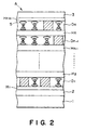
- Figures 1A, 1B and 2 respectively illustrate a laminar structure of a display medium according to the present invention.
- Figure 3 is a diagram showing a temperature control pattern for selecting and erasing each layer of a display medium independently from the other layers.
- Figures 4 and 5 are schematic views illustrating display methods using a display medium of Example 1 and Example 2, respectively.
- Figure 6 is an illustration of a thermal head used in the present invention and Figure 7 is a plan view showing an example of a split pattern of such a thermal head.
- Figure 8 is a view illustrating a laminar structure of a second embodiment of the display medium according to the present invention.
- Figure 9 is a diagram showing a relationship between a temperature and a transmittance (or a scattering intensity) of a polymer liquid crystal used in a second polymer layer.
- Figures 10 and 12 respectively show a relationship between mesomorphic temperature ranges of first and second polymer layers.
- Figures 11 and 13 respectively show an energy pulse pattern applied to a thermal head in first and second steps in a display method of the present invention.
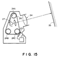
- Figures 14A, 14B and 15 are schematic views for illustrating display apparatus using display media of the present invention.
- Figures 1A and 1B are schematic views each illustrating a laminar structure of a display medium according to the present invention.
- a display medium of the present invention comprises a substrate 1 and a first display layer D 1 and a second display layer D 2 disposed in this order on the substrate 1.
- the display medium can comprise an intermediate layer H between the first and second display layers ( Figure 2).
- the first display layer D 1 and the second display layer D 2 respectively comprise a polymer liquid crystal.
- Each of the first (D 1 ) and second (D 2 ) display layers has has its own mesomorphic (phase) temperature range, i.e., a temperature range between its glass transition temperature and the upper limit temperature of a liquid crystal phase to be used for display, preferably a temperature range between its glass transition temperature and its mesomorphic-isotropic phase transition temperature.
- the upper limit temperature of a liquid crystal phase for display can be defined within a single liquid crystal phase (e.g., cholesteric phase) as a temperature providing different visual effects below and above the temperature (because of a change in cholesteric pitch).
- the first and second display layers (D 1 and D 2 ) are required to have mesomorphic temperature ranges which are distinct from (i.e., not overlapping) each other between the first and second display layers.
- the difference between two mesomorphic temperature ranges may preferably be 5 o C or more.
- each display layer comprises a different polymer liquid crystal comprising different glass transition temperature and phase-transition temperature.
- a display layer comprises a mixture of, e.g., two or more polymer liquid crystals, it is sufficient that the display layer shows a different glass transition temperature and a phase transition temperature as the mixture.
- the polymer liquid crystal used in the present invention may be a thermotropic main chain-type or side chain-type polymer liquid crystal showing a mesomorphic phase, such as nematic phase, smectic phase, chiral nematic phase or chiral smectic phase within a temperature range of from 0 °C to 300 °C. Below 0 °C, the temperature control becomes difficult, and above 300 °C, an excessively large energy is required. It is important for the polymer liquid crystal to have a glass transition point so that its mesomorphic or liquid crystal texture can be fixed without a particular holding operation in order to provide a display with a memory characteristic.
- the polymer liquid crystal used in the present invention may preferably have 5 or more recurring units.
- the polymer liquid crystal showing chiral nematic phase or chiral smectic phase may also be of a side chain-type having a mesogen unit in its side chain or a main chain-type having a mesogen unit in its main chain.
- the main chain-type polymer liquid crystal may comprise a mesogen unit, a flexible chain and an optically active group, which have been combined into a polymer by the medium of, e.g., an ester bond, amide bond, peptide bond, urethane bond or ether bond.
- An ester bond may preferably be used.
- Example compounds used as mesogen unit sources may include: dicarboxylic acids, such as terphenyldicarboxylic acid, p-terephthalic acid, biphenyldicarboxylic acid, stilbenedicarboxylic acid, azobenzenedicarboxylic acid, azoxybenzenedicarboxylic acid, cyclohexanedicarboxylic acid, biphenyl etherdicarboxylic acid, biphenoxyethanedicarboxylic acid, and carboxycinnamic acid; diols, such as hydroquinone, dihydroxybiphenyl, dihydroxyterphenyl, dihydroxyazobenzene, dihydroxyazoxybenzene, dihydroxydimethylazobenzene, dihydroxydimethylazoxybenzene, dihydroxypyridazine, dihydroxynaphthalene, dihydroxyphenyl ether, and bis(hydroxyphenoxy)ethane; and hydroxycarboxylic acids, such as hydroxybenzoic acid
- Example compounds used as flexible chain sources may include: diols, such as methylene glycol, ethylene glycol, propanediol, butandiol, pentanediol, hexanediol, heptanediol, octanediol, nonanediol, decanediol, undecanediol, dodecanediol, tridecanediol, tetradecanediol, pentadecanediol, diethylene glycol, triethylene glycol, tetraethylene glycol, nonaethylene glycol, and tridecaethylene glycol; and dicarboxylic acids, such as malonic acid, succinic acid, glutaric acid, adipic acid, pimelic acid, suberic acid, azelaic acid, and sebacic acid.
- diols such as methylene glycol, ethylene glycol, propanediol,
- Source compounds for providing an optically active group may preferably be difunctional ones, examples of which may include the following: (+)-3-methyl-1,6-hexanediol, (-)-3-methyl-1,6-hexandiol, (+)-3-methyladipic acid, (-)-3-methyladipic acid, (D)-mannitol, (L)-mannitol, (+)-pantothenic acid, (+)-1,2,4-trihydroxy-3,3-dimethylbutane, (-)-1,2-propanediol, (+)-1,2-propanediol, (+)-lactic acid, (-) lactic acid, (2S,5S)-2-methyl-3-oxahexane-1,5-diol, (2S, 5S, 8S)-2,5-dimethyl-3,6-dioxanonane-1,8-diol.
- the polymer liquid crystal having an asymmetric carbon atom may be obtained by polycondensation of a mesogen unit-source compound, a flexible chain-source compound and an optically active group-source compound selected from those described above.
- a catalyst it is possible to use a catalyst in order to increase the degree of polymerization and decrease impurities due to side reactions, etc. In such a case, it is desirable to remove the catalyst after completion of the polycondensation.
- Examples of the main chain-type polymer liquid crystal may include those represented by the following formulas (13) - (25), wherein n is 5 - 1000.
- the polymer liquid crystal showing a nematic or smectic phase may also be of a main chain-type or a side chain-type. Such a polymer liquid crystal does not have an optically active group so that it does not show a helical structure.
- a composition comprising a polymer liquid crystal as described above and a low-molecular weight liquid crystal mixed in appropriate proportions under heating or in the presence of a common solvent.
- the low-molecular weight liquid crystal should be compatible with a polymer liquid crystal and may preferably be one having an asymmetric carbon center. Specific examples thereof may include chiral liquid crystals represented by the following formulas (35) - (49), but these are not exhaustive. In the following formulas, the respective symbols denote the following phases.
- polymer liquid crystal composition comprising a polymer liquid crystal and a low-molecular weight liquid crystal
- the polymer liquid crystal is contained in a proportion of 50 wt. % or more, preferably 70 wt. % or more. Below 50 wt. %, it is difficult to effect sufficient fixation of a display state.
- various polymer liquid crystals such as discotic polymer liquid crystals and thermotropic mesomorphic glutamic acid copolymers, may also be used.
- laser light when used as a heating means, it is effective to add a light-absorbing agent corresponding to the wavelength of the laser light.
- Such a polymer liquid crystal or a polymer liquid crystal composition obtained from such a polymer liquid crystal may be used in a separate film or may be formed in a layer disposed on a substrate.
- Each polymer liquid crystal layer may have a thickness of 1 - 200 microns, preferably 5 - 100 microns.
- the substrate 1 used in the present invention may be composed of an arbitrary material, such as glass, plastic or metal, and a transparent electrode of, e.g., ITO film or a patterned electrode can be formed thereon as desired.
- a transparent electrode of, e.g., ITO film or a patterned electrode can be formed thereon as desired.
- the display layer D 1 or D 2 may be formed on such a substrate 1 by forming a coating liquid of a polymer liquid crystal or its composition as by heat melting or dissolution in a solvent and applying the coating liquid on the substrate by spin coating, casting, dipping, bar coating, roller coating, gravure coating, doctor blade, etc.
- polymer liquid crystals having different helical pitches can be used.
- screen printing, patterning by using a photoresist or the like may be suitably used.
- a display medium having a plurality of display layers, D 1 , D 2 , ... having different mesomorphic temperature ranges can be formed by repeating the above-mentioned application step.
- an intermediate layer H can be inserted between adjacent display layers, D 1 , D 2 ... comprising polymer liquid crystals ( Figure 2).
- the intermediate layer H may be used to prevent a direct contact between adjacent display layers.
- the intermediate layer can be composed of an electrode but may generally be formed as an insulating layer composed of an inorganic material, such as silicon monoxide, silicon dioxide, aluminum dioxide, zirconia, magnesium fluorides cerium oxide, cerium fluoride, silicon nitride, or boron nitride; or an organic material, such as polyvinyl alcohol, polyimide, polyamide-imide, polyester-imide, polyparaxylylene, polyester, polycarbonate, and polyvinyl acetal.
- an inorganic material such as silicon monoxide, silicon dioxide, aluminum dioxide, zirconia, magnesium fluorides cerium oxide, cerium fluoride, silicon nitride, or boron nitride
- organic material such as polyvinyl alcohol, polyimide, polyamide-imide, polyester-imide, polyparaxylylene, polyester, polycarbonate, and polyvinyl acetal.
- the intermediate layer H may have a thickness in the range of 0.1 - 100 microns. Below 0.1 micron, a sufficient separation effect cannot be attained. In excess of 100 microns, a sufficient heat transfer between adjacent display layers cannot be effect and a heat diffusion is caused in the intermediate layer so that color deviation of written parts occurs between the adjacent display layers.
- the intermediate layer may preferably have a thickness in the range of 0.5 - 10 microns.
- the intermediate layer can also be composed as an alignment layer of an insulating film provided with an alignment control function.
- Such an alignment film is used particularly effectively when a chiral display layer is used for color image display.
- the alignment film may preferably be one subjected to a homogeneous orientation or aligning treatment.
- the homogeneous aligning treatment may be performed by stretching under the action of a mechanical force, roller stretching, shearing, application of an electric field or magnetic field or interfacial control.
- a homogeneous aligning treatment by interfacial control is particularly preferred.
- homogeneous aligning treatment by interfacial control may include the following.
- a substrate is coated with an alignment control film by forming a film of, e.g., an inorganic insulating substance, such as silicon monoxide, silicon dioxide, aluminum oxide, zirconia, magnesium fluoride, cerium oxide, cerium fluoride, silicon nitride, silicon carbide or boron nitride; or an organic insulating substance, such as polyvinyl alcohol, polyimide, polyamide-imide, polyester-imide, polyparaxylylene, polyester, polycarbonate, polyvinyl acetal, polyvinyl chloride, polyamide, polystyrene, cellulosic resin, melamine resin, urea resin or acrylic resin, by application of a solution, vapor deposition or sputtering.
- an inorganic insulating substance such as silicon monoxide, silicon dioxide, aluminum oxide, zirconia, magnesium fluoride, cerium oxide, cerium fluoride, silicon nitride, silicon carbide or boron nitride
- the alignment control film formed as a film of an inorganic insulating substance or organic insulating substance as described above may then be rubbed in one direction with velvet, cloth or paper on the surface thereof.
- An oxide such as SiO, a fluoride, or a metal such as Au or Al or its oxide, is vapor-deposited on a substrate in a direction forming an angle inclined with respect to the substrate.
- An organic or inorganic insulating film as described in (1) above formed on a substrate is etched by radiation with an ion beam or oxygen plasma incident in an oblique direction.
- a film of obtained by stretching a film of a polymer such as polyester or polyvinyl alcohol also shows a good orientation characteristic.
- Grooves are formed on a substrate surface by photolithography, stampling or injection, so that liquid crystal molecules are aligned along the grooves.
- the alignment film may preferably be one subjected to a homeotropic orientation or aligning treatment.
- the homeotropic aligning treatment may be performed by stretching under the action of a mechanical force, roller stretching, shearing, application of an electric field or magnetic field, or interfacial control.
- a homeotropic aligning treatment by interfacial control is particularly preferred.
- homeotropic aligning treatment by interfacial control may include the following.
- a substrate surface is coated with a layer of an organic silane, lecithin or PTFE (polytetrafluoroethylene) having a homeotropic orientation characteristic.
- organic silane lecithin
- PTFE polytetrafluoroethylene
- Oblique vapor deposition is performed on a substrate while the substrate is rotated and the vapor deposition angle is appropriately selected to provide a homeotropic orientation characteristic. Further, it is also possible to apply a homeotropic aligning agent as shown in (1) above after the oblique vapor deposition.
- orientation or aligning treatments as described above may be used singly or in combination of two or more methods.
- the optical densities of the respective display layers can be independently controlled. Further, if each layer is controlled to assume a transparent, opaque or intermediate color state, more levels of intermediate tones can be displayed.
- FIG. 2 is a schematic sectional view illustrating a display medium A comprising display layers in which helical structures are formed.
- the display medium A according to the present invention comprises a substrate 1 having thereon a light-absorbing layer 2 on which are successively further disposed a first alignment layer H 1 , a first display layer D 1 , a second alignment layer H 2 , a second display layer D 2 , ... an n-th alignment layer H n , an n-th display layer D n , an (n+1)th alignment layer H n+1 , and a surface protective layer 3.
- the polymer liquid crystals having a chiral phase and constituting the first to n-th display layers have mutually distinct mesomorphic temperature ranges each defined as a temperature range from a glass transition temperature to the upper limit of a liquid crystal phase used for display.
- a light-absorbing layer 2 may be disposed so as to provide an increased contrast by absorbing light other than that given by selective scattering.
- a light-absorbing layer is constituted to have an optical density of 1.0 or higher, e.g., as a resin layer containing a black pigment such as carbon black.
- the surface protective layer 3 may be disposed so that the surface of the display layer is not damaged as by thermal degradation or thermal distortion, e.g., when writing or erasure is effected by a thermal head.
- a surface protective layer may be composed of three-dimensionally crosslinked fluorine-containing resin, polysiloxane resin, acrylic resin or methacrylic resin.
- the thickness of the protective layer may be 0.1 micron to 100 microns.
- the n-th display layer D n is assumed to have a glass transition temperature TG n and a liquid crystal phase upper limit temperature TC n .
- An n-th layer is assumed to be heated to TAn and an (n-1)th layer having, e.g., a lower mesomorphic temperature range than the n-th layer is assumed to be heated to TA n-1, respectively, e.g., by a thermal head.
- TA n > TC n > TG n ⁇ TA n-1 the number ( n ) of display layers need not be laminated in the order of their mesomorphic temperature ranges but can be laminated in a random order.
- a pixel concerned is heated up to TA n and cooled to the temperature of TC n and then gradually cooled to TG n , followed by rapid cooling, so that the pixel in the n-th display layer is fixed in the liquid crystal phase.
- pixels other than the pixel concerned are heated to TA n and then rapidly cooled so that all the layers including the n-th layer are fixed in their amorphous phase to provide a transparent state and allow a light absorption at the light-absorbing layer 2.
- a pixel concerned is heated to TA n-1 and then rapidly cooled to TC n-1 , followed by gradual cooling down to TG n-1 and then rapid cooling, to fix the (n-1)th layer in a light-scattering liquid crystal state while the layers other than the (n-1)th layer are fixed in a transparent amorphous state so as to allow a light absorption at the light-absorbing layer 2.
- the three display layers include a display layer (® layer) showing a selective scattering at around 650 nm, a display layer (G layer) showing a selective scattering at around 550 nm, and a display layer (B layer) showing a selective scattering at around 450 nm.
- the respective layers are assumed to have glass transition temperatures TG ®, TG G and TG B and liquid crystal phase transition temperatures (to a high temperature phase, e.g., isotropic phase) TC®, TC G and TC B. Further, these layers are are assumed to be heated to three levels of temperatures TA 1 , TA 2 and TA 3 .
- Figure 3 shows a temperature control pattern for independently selecting (writing in a scattering state) or erasing (into a transparent state) the ®, G and B layers when the following relationship is satisfied: TA 3 > TC ® > TG ® ⁇ TA 2 > TC G ⁇ > TG G ⁇ ⁇ TA 1 > TC B ⁇ > TG B ⁇
- the selection (into a light scattering state) and erasure (into a transparent state) of the respective layers can be effected.
- the degree of liquid-crystallinity of each layer can be controlled by changing the heating temperature, holding time and cooling rate of the layer, so that optical density of the layer can be controlled continuously.
- a gradational display of R, G and B can be effected for each pixel, and a highly fine image display with a full color can be effected without color deviation.
- the present invention by arranging two or more heating means, such as thermal heads 4 in the direction of sequentially performing recording and erasure on a display medium A as shown in Figure 6, so that the pixels in the display layer are sequentially selected by the heating means to effect the temperature modulation of a polymer liquid crystal therein, whereby the optical density of each layer can be controlled independently for each pixel.
- thermal head used in the present invention can be a split-type one having a plurality of split heating elements as shown in Figure 7 so as to effect a multi-level heating.
- a display apparatus used in a display method as described above may preferably comprise a display medium as described above, means for sequentially selecting a pixel in a display layer of the display medium and heating means comprising two or more thermal heads arranged in the direction of sequentially effecting recording and erasure on the display medium.
- the present invention also provides a display medium as shown in Figure 8, which comprises on a substrate 1, a first polymer layer 21 comprising a chiral polymer liquid crystal (as a first display layer D 1 in Figure 1) and a second polymer layer 22 capable of providing a light-scattering state (as a second display layer D 2 ).
- the first polymer layer 21 may suitably comprise a side chain-type or main chain-type polymer liquid crystal showing cholesteric liquid crystal phase or chiral smectic liquid crystal phase as a mesomorphic phase, which can select a state of reflecting or transmitting a selected wavelength of visible light and fix the state by changing the temperature.
- the second polymer layer 22 may suitably comprise a side chain-type or main chain-type thermotropic polymer liquid crystal comprising, as a main chain, methacrylic acid polymer, siloxane polymer, polyester-type polymer or polyamide-type polymer and a low-molecular weight liquid crystal or mesogen unit in its side chain in a pendant form or in its main chain.
- the second polymer layer 22 may assume a mesomorphic phase of smectic, chiral smectic, nematic or cholesteric phase, or further a discotic phase.
- Specific polymer liquid crystals constituting the first polymer layer or the second polymer layer can be selected from the above-mentioned examples (1) - (34) (and can also be combined with low-molecular weight liquid crystal examples (35) - (49)) depending on the desired conditions. Further, examples suitable to constitute the second polymer layer may include those represented by the following formulas (50) - (53):
- the function of the second polymer layer 22 will now be explained based on a specific example wherein a polymer liquid crystal of the above formula (50) was used.
- the above polymer liquid crystal (50) was dissolved in dichloroethane at a concentration of 20 wt. % and the solution was applied by an applicator on a polyester transparent substrate washed with alcohol, followed by standing at 95 °C for 10 minutes to form a white scattering film in a thickness of about 10 microns.
- the thus obtained white sheet was scanned in a pattern of character or figure by a thermal head, whereby a white pattern corresponding to the scanned pattern was fixed.
- a white pattern corresponding to the scanned pattern was fixed.
- a clear black display was obtained against the white background.
- the sheet was projected by means of an ordinary overhead projector (OHP), whereby a clear white image was displayed on a screen.
- OHP ordinary overhead projector
- the whole area of the above sheet having the above-mentioned pattern was heated to about 120 °C and then heated at about 90 °C for several seconds, whereby the original white scattering state was restored on the whole area and stably retained even if cooled to room temperature as it was, so that additional recording and display were possible.
- the above series of phenomena can be controlled based on the fact that the above-mentioned polymer liquid crystal can assume at least three states including a film state below the glass transition point where it retains a stable memory state, a liquid crystal state where it can be transformed into a substantially optical scattering state and an isotropic film state at a higher temperature where it assumes an isotropic molecular alignment.
- the above-mentioned scattering state corresponds to a state 1.
- a heating means such as a thermal head or laser light
- T 2 isotropic state transition temperature
- a light-transmissive state as shown by 3 similar to the isotropic state is fixed.
- “rapid cooling” means cooling at a rate sufficiently large as to fix the state before the cooling without substantial growth of an intermediate or mesomorphic state, such as a lower-temperature liquid crystal phase.
- Such a rapid cooling condition can be realized without a particular cooling means and by having the recording medium stand in air for natural cooling.
- the thus-fixed isotropic state is stable at a temperature below T 1 (Tg: glass transition point), such as room temperature or natural temperature, and is stably used as an image memory.
- the polymer liquid crystal layer heated to above T 2 as indicated by a curve is held at a liquid crystal temperature between T 1 and T 2 for a period of, e.g., 1 second to several seconds, the polymer liquid crystal layer increases the scattering intensity during the holding period as indicated by a curve to be restored to the original scattering state 1 room temperature.
- the resultant state is stably retained at a temperature below T 1 .
- the polymer liquid crystal layer is cooled while taking a liquid crystal temperature between T 1 - T 2 for a period of, e.g., about 10 milliseconds to 1 second as indicated by curves 2, an intermediate transmissive state is obtained at room temperature, thus providing a gradation.
- the resultant transmittance or scattering intensity may be controlled by controlling the holding period at a liquid crystal temperature after heating into an isotropic state and until cooling to room temperature.
- the resultant state may be stably retained below T 1 .
- the velocity of restoring to the original scattering state is larger at a temperature closer to T 2 in the liquid crystal temperature range. If the medium is held at a temperature within the liquid crystal temperature range for a relatively long period, the scattering state 1 can be restored without heating once into isotropic phase or regardless of the previous state.
- a polymer liquid crystal showing an optical scattering state and a transparent state in the above-described manner is optimally used to constitute the second polymer layer.
- a phase separation polymer or another phase transition polymer showing a light-scattering effect through another known mechanism can also be used to constitute the second polymer layer.
- the display medium comprising a chiral first polymer layer and a second polymer layer capable of showing a light-scattering state
- the display medium is supplied with thermally controlled image data to control the chiral pitch of the first polymer layer so as to provide a desired wavelength for selective scattering reflection or transmittance while providing the second polymer layer with a light-transmissive state.
- either one of the first and second polymer layers having a higher mesomorphic range is first subjected to selection of a display state.
- a thermal signal for controlling the chiral pitch of the first polymer layer to provide a desired color may be applied in a first step, and a thermal signal for determining the transmissive state of the second polymer layer may be applied in a second step.
- the thermal signal for determining the transmissive state of the second polymer layer applied in the second step may preferably be one comprising gradation data ( Figures 10 and 11).
- a thermal signal for determining the transmissive state of the second polymer layer may be applied in a first step, and a thermal signal for controlling the chiral pitch of the first polymer layer to provide a desired color may be applied in a second step.
- the thermal signal for determining the transmissive state of the second polymer layer applied in the first step may preferably be one comprising gradation data ( Figures 12 and 13).
- the above-mentioned display or color presentation function of the display medium according to the present invention may be attained in both of a case wherein the second polymer layer is disposed on the first polymer layer and a thermal means is actuated from the side of the second polymer layer, and a case wherein the first polymer layer is disposed on the second polymer layer and a thermal means is actuated from the side of the first polymer layer.
- the thermal means is a thermal head
- a thin protective layer of silicone resin, fluorine-containing resin, polyimide, etc. may be disposed on an upper one of the first and second polymer layers.
- the first polymer layer is disposed as a lower layer on a substrate 1
- a uniaxial aligning treatment such as rubbing or a homeotropic alignment layer
- a display medium of the present invention as shown in Figure 1A, 1B, 2 or 8 described above may be incorporated in a display apparatus as shown in Figure 14A, 14B or 15 to provide a display of a direct view-type or projection-type.
- a display apparatus shown in Figure 14A comprises a display medium 26 as described above, a thermal head 23 of a multi-head type, a drive roller 24, a backing plate 25 of a chromatic color or black, a planar heater 27, a temperature sensor 28, a temperature sensor 29, a halogen lamp 30, a roller (halogen heater) 31, and a display zone 32.
- the lower part of the apparatus shown in Figure 14A can be modified to comprise a thermal head 33 of a serial head-type and a platen 34 as shown in Figure 14B.
- a display apparatus shown in Figure 15 comprises a display medium 26 as described above in the form of an endless belt wrapped around drive rollers 24A - 24C, a thermal head 23, a projection optical system 34 and a screen 35.
- a color image displayed on a white background may be directly observed.
- a luminescent color image is displayed on the background of a dark color. This is attained as an effect the second polymer layer disposed as a light-scattering layer.
- a thermal head 4 movably mounted on a head driver 7 and controlled by a thermal head temperature controller 6 was actuated to heat a display pixel to 290 o C and turned off to cool the pixel to 100 °C. Then, the thermal head 4 was controlled to gradually cool the pixel to room temperature in 30 seconds, whereby a red color was displayed at the pixel.
- the thermal head 4 was actuated to heat and hold a pixel at 270 o C and then turned off to rapidly cool the pixel to room temperature, whereby a green color was displayed.
- the thermal head 4 was actuated to heat a pixel to 290 o C and then the energy thereto was gradually decreased to zero in 5 minutes, whereby a yellow color was displayed. When the energy was decreased to zero in 1 minute, a reddish yellow color was displayed.
- IR-750 infrared absorber
- Mw 20000 (calculated as polystyrene) based on GPC) mixed with 1 wt. % thereof of an infrared absorber (IR-759), followed by drying to form an about 20 micron-thick display layer (IV layer).
- the laminate thus formed was held at 90 o C for 5 hours and observed through a polarizing microscope, whereby SmC* (chiral smectic C phase) was observed in the display layer (IV layer).
- the display medium A thus obtained was incorporated in a system as shown in Figure 5 and illuminated with laser light having a wavelength of 780 nm generated from and a semiconductor laser 9 driven by a laser driver 13 and passed through a collimator lens 10 and a condenser (objective) lens 11 driven by a driver 12.
- the laser light was incident at a power of 10 mW for a spot diameter of 5 microns, once turned off and then again caused to be incident at a power of 1 mW, whereby a record of a blue-white color was displayed only at the III layer.
- the laser light was incident at 10 mW, gradually decreased to 8 mW and then turned off, whereby a white-colored record was displayed only at the V layer. Then, the laser light was first incident at 10 mW, once turned off, again incident at 5 mW and then again turned off, whereby a yellow-white record was formed only at the IV layer.
- the laser light was first incident at 10 mW and gradually turned off in 5 minutes, whereby a white color was displayed. On the other hand, when the laser light was turned off in 30 sec, a blue black color was displayed.
- Tg 2 glass transition temperature
- Tm 2 mesomorphic range upper limit
- the second polymer layer of the formula (50) showing a light-scattering state in the mesomorphic phase assumed a transparent isotropic state above 120 °C.
- the display medium having a structure as shown in Figure 8 prepared above was heated to 140 °C, held thereat for 30 °C and rapidly cooled to room temperature at a rate of more than 100 °C/min, whereby a green display was obtained.
- a green display was obtained.
- a red display was obtained when the medium was held at 150 °C followed by rapid cooling
- a blue display was obtained when the medium was held at 130 °C followed by rapid cooling.
- a temperature distribution image in a range exceeding 120 °C imparted to the display medium could be converted into a color image.
- the method (3) is particularly effective.
- a second step is provided for selecting a temperature above Tg 2 of the second polymer layer or the time for keeping the temperature to substantially fix the color of the first polymer layer and control the transmissivity of the second polymer layer depending on given gradation data.
- Figure 11 is a diagram schematically illustrating the above procedure in the form an energy pulse level applied to a thermal head.
- the mesomorphic temperature ranges of the first and second polymer layers can overlap each other to some extent, but a relationship of Tm 2 (isotropic transition temperature of the second polymer layer) ⁇ Tg 1 (glass transition temperature of the first polymer layer) may preferably be satisfied in order to provide a better control in image formation.
- the images formed in Examples 3 and 4 can be erased by heating the display medium once at least above the isotropic transition temperature of the second polymer layer, followed by gradual cooling to provide a superficially uniform white scattering state.
- thermotropic polymer liquid crystal of the above formula (VII) is a liquid crystal showing a cholesteric phase in the range of 110 °C to a little higher than 200 °C in which the liquid crystal shows a dynamic range of about 110 - 135 °C for selective scattering or transmittance in visible region.
- the second polymer layer of the formula (53) showing a light-scattering in the mesomorphic state assumes a transparent isotropic state above 200 °C. Accordingly, when the display medium in a laminated structure shown in Figure 8 is heated to an appropriate temperature and then rapidly cooled to a temperature below the glass transition point of the second polymer layer, the second polymer layer 22 is fixed in a transparent state. Alternatively, when the heating temperature above the glass transition temperature or the cooling speed down to below the glass transition temperature of the second polymer layer is appropriately selected, an intermediately transmissive state, i.e., so-called gradational display, can be realized.
- an intermediately transmissive state i.e., so-called gradational display
- the first polymer layer shows a dynamic range for presenting color in visible region in the neighborhood of or just below the glass transition point (140 °C) of the second polymer layer. Accordingly, after determining the transmissivity or clarity of the second polymer layer and during the course of cooling down to room temperature, a temperature control may be effected to determine the color of the first polymer layer.
- a color image is formed and fixed on the display medium according to the present invention through a thermal control including a first step for providing a temperature distribution determining the transmissivity of the second polymer layer and a second step for providing a temperature distribution determining the color presentation of the first polymer layer.
- the above-mentioned temperature distribution may be provided by modulating the pulse duty or voltage level of a voltage pulse applied to a thermal head depending on desired colors.
- the image formed is provided with a color density so that a full color display can be realized in principle.
- Figure 13 is a diagram schematically illustrating the above procedure in the form an energy pulse level applied to a thermal head.
- the mesomorphic temperature ranges of the first and second polymer layers can overlap each other to some extent, but a relationship of Tm 1 (isotropic transition temperature of the first polymer layer) ⁇ Tg 2 (glass transition temperature of the second polymer layer) may preferably be satisfied in order to provide a better control in image formation.
- the images formed the above-described manner can be erased by heating the display medium above the isotropic transition temperature of the second polymer layer, followed by gradual cooling to provide superficially uniform white scattering state.
- a plurality of display layers of the display medium can be independently controlled with respect to one or more layers.
- each pixel can be controlled with respect to a color and its density, so that a full-color highly fine image display can be realized.
Landscapes
- Chemical & Material Sciences (AREA)
- Physics & Mathematics (AREA)
- Crystallography & Structural Chemistry (AREA)
- Engineering & Computer Science (AREA)
- Materials Engineering (AREA)
- Organic Chemistry (AREA)
- Nonlinear Science (AREA)
- General Physics & Mathematics (AREA)
- Optics & Photonics (AREA)
- Mathematical Physics (AREA)
- Liquid Crystal (AREA)
Claims (19)
- Anzeigemedium, das eine Anzeigevorderseite hat und eine laminierte Anzeigeschicht parallel zu der Anzeigevorderseite aufweist, wobei diese Anzeigeschicht einen polymeren Flüssigkristall aufweist, der einen mesomorphen Temperaturbereich zwischen seiner Glasübergangstemperatur und der oberen Grenztemperatur einer Flüssigkristallphase zur Anzeige zeigt, wobei die laminierte Anzeigeschicht angeordnet ist, einen Anzeigezustand unter ihrer Glasübergangstemperatur zu bewahren, die gemäß ihrer thermischen Gesetzmäßigkeiten über der Glasübergangstemperatur ausgewählt wird, dadurch gekennzeichnet, daß diese laminierte Anzeigeschicht eine Vielzahl von Anzeigeschichten ist, die jeweils verschiedene polymere Flüssigkristallzusammensetzungen enthalten und angeordnet sind jeweils verschiedene dieser Anzeigezustände zu bewahren, die zu den thermischen Gesetzmäßigkeiten über der oberen Grenze und zwischen dieser oberen Grenze und der Glasübergangstemperatur korrespondieren; und daß die mesomorphen Temperaturbereiche dieser Vielzahl von Anzeigeschichten nicht einander überlappen, so daß die Auswahl des Anzeigezustands einer Schicht im wesentlichen unabhängig von der Auswahl des Anzeigezustands der anderen Anzeigeschichten bei einem speziellen Anzeigepunkt ist.
- Anzeigemedium gemäß Anspruch 1, worin eine aus der Vielzahl von Anzeigeschichten eine Glasübergangstemperatur hat, die höher als die mesomorphe isotrope Übergangstemperatur einer anderen Anzeigeschicht ist.
- Anzeigemedium gemäß Anspruch 1, worin diese Vielzahl von Anzeigeschichten polymere Flüssigkristalle enthalten, die spiralartige Strukturen mit verschiedenen Spiralsteigungen hahen.
- Anzeigemedium gemäß Anspruch 3, worin die polymeren Flüssigkristalle, die spiralartige Strukturen haben, eine einschließen, die eine chirale nematische Phase zeigt.
- Anzeigemedium gemäß Anspruch 3, worin die polymeren Flüssigkristalle, die spiralartige Strukturen haben, eine einschließen, die eine chirale smektische Phase zeigt.
- Anzeigemedium, das eine Anzeigevorderseite hat und eine laminierte Anzeigeschicht parallel zu der Anzeigevorderseite aufweist, wobei diese Anzeigeschicht einen polymeren Flüssigkristall aufweist, der einen mesomorphen Temperaturbereich zwischen seiner Glasübergangstemperatur und der oberen Grenztemperatur einer Flüssigkristallphase zur Anzeige zeigt, wobei die laminierte Anzeigeschicht angeordnet ist, einen Anzeigezustand unter ihrer Glasübergangstemperatur zu bewahren, die gemäß ihrer thermischen Gesetzmäßigkeiten über der Glasübergangstemperatur ausgewählt wird, dadurch gekennzeichnet, daß diese laminierte Anzeigeschicht eine Vielzahl von Anzeigeschichten ist und eine erste Anzeigeschicht, die eine chirale Struktur zeigt und eine zweite Anzeigeschicht einschließt, die einen Lichtstreuungs-Zustand zeigt, wobei die erste und die zweite Anzeigeschicht jeweils verschiedene polymere Flüssigkristallzusammensetzungen enthalten und angeordnet sind jeweils verschiedene dieser Anzeigezustände zu bewahren, die zu den thermischen Gesetzmäßigkeiten über der oberen Grenze und zwischen dieser oberen Grenze und der Glasübergangstemperatur korrespondieren; und daß die mesomorphen Temperaturbereiche dieser ersten und zweiten Anzeigeschicht nicht einander überlappen, so daß die Auswahl des Anzeigezustands einer Schicht im wesentlichen unabhängig von der Auswahl des Anzeigezustands der anderen Anzeigeschichten bei einem speziellen Anzeigepunkt ist.
- Anzeigemedium gemäß Anspruch 6, worin eine der ersten und zweiten Anzeigeschichten eine Glasübergangstemperatur hat, die höher als die mesomorphe isotrope Übergangstemperatur von der anderen der ersten und zweiten Anzeigeschichten ist.
- Anzeigeverfahren umfassend:
Bereitstellung eines Anzeigemedium, wie in Anspruch 1 definiert und Kontrolle der optischen Dichten der Anzeigeschichten unabhängig von den anderen Anzeigeschichten oder der anderen Anzeigeschicht. - Anzeigeverfahren gemäß Anspruch 8, worin die optischen Dichten durch Temperaturmodulation mittels eines thermischen Kopfes kontrolliert werden.
- Anzeigeverfahren gemäß Anspruch 8, worin die optischen Dichten durch Temperaturmodulation mittels eines Lasers kontrolliert werden.
- Anzeigeverfahren umfassend: Bereitstellung eines Anzeigemedium wie in Anspruch 6 definiert und Kontrolle der optischen Dichten der Anzeigeschichten unabhängig von den anderen Anzeigeschichten oder der anderen Anzeigeschicht.
- Anzeigeverfahren gemäß Anspruch 11, worin die optischen Dichten durch Temperaturmodulation mittels eines thermischen Kopfes kontrolliert werden.
- Anzeigeverfahren gemäß Anspruch 11, worin die optischen Dichten durch Temperaturmodulation mittels eines Lasers kontrolliert werden.
- Anzeigevorrichtung umfassend ein Anzeigemedium, wie in Anspruch 1 definiert und Kontrollmittel zur Kontrolle der optischen Dichten der jeweiligen Anzeigeschichten unabhängig von den anderen Anzeigeschichten oder der anderen Anzeigeschicht.
- Anzeigevorrichtung gemäß Anspruch 14, worin dieses Kontrollmittel einen thermischen Kopf aufweist.
- Anzeigevorrichtung gemäß Anspruch 14, worin dieses Kontrollmittel einen Laser aufweist.
- Anzeigevorrichtung umfassend ein Anzeigemedium, wie in Anspruch 6 definiert und Kontrollmittel zur Kontrolle der optischen Dichten der jeweiligen Anzeigeschichten unabhängig von den anderen Anzeigeschichten oder der anderen Anzeigeschicht.
- Anzeigevorrichtung gemäß Anspruch 17, worin dieses Kontrollmittel einen thermischen Kopf aufweist.
- Anzeigevorrichtung gemäß Anspruch 17, worin dieses Kontrollmittel einen Laser aufweist.
Applications Claiming Priority (6)
| Application Number | Priority Date | Filing Date | Title |
|---|---|---|---|
| JP63146794A JP2614082B2 (ja) | 1988-06-16 | 1988-06-16 | 表示媒体、その表示方法および表示装置 |
| JP14679688A JPH022514A (ja) | 1988-06-16 | 1988-06-16 | 像形成媒体およびその像形成方法 |
| JP146794/88 | 1988-06-16 | ||
| JP146795/88 | 1988-06-16 | ||
| JP63146795A JPH022513A (ja) | 1988-06-16 | 1988-06-16 | 像形成媒体およびその像形成方法 |
| JP146796/88 | 1988-06-16 |
Publications (2)
| Publication Number | Publication Date |
|---|---|
| EP0346911A1 EP0346911A1 (de) | 1989-12-20 |
| EP0346911B1 true EP0346911B1 (de) | 1997-03-12 |
Family
ID=27319235
Family Applications (1)
| Application Number | Title | Priority Date | Filing Date |
|---|---|---|---|
| EP89110908A Expired - Lifetime EP0346911B1 (de) | 1988-06-16 | 1989-06-15 | Anzeigemedium, Anzeigeverfahren und -vorrichtung |
Country Status (3)
| Country | Link |
|---|---|
| US (1) | US5066107A (de) |
| EP (1) | EP0346911B1 (de) |
| DE (1) | DE68927837T2 (de) |
Families Citing this family (23)
| Publication number | Priority date | Publication date | Assignee | Title |
|---|---|---|---|---|
| US5272552A (en) * | 1988-05-11 | 1993-12-21 | Canon Kabushiki Kaisha | Optical modulation device and method using modulation layer of helical polymer liquid crystal having a helical chiral smectic C phase |
| JPH07119910B2 (ja) * | 1989-04-14 | 1995-12-20 | 松下電器産業株式会社 | 液晶パネルの製造方法 |
| JP2851906B2 (ja) * | 1990-03-23 | 1999-01-27 | キヤノン株式会社 | 光学変調素子及び表示装置 |
| JPH03278768A (ja) * | 1990-03-28 | 1991-12-10 | Sharp Corp | 画像形成システム |
| JPH0422917A (ja) * | 1990-05-18 | 1992-01-27 | Nippon Oil Co Ltd | 旋光性光学素子 |
| JP3002757B2 (ja) * | 1990-07-04 | 2000-01-24 | キヤノン株式会社 | 画像形成方法、記録媒体、及び可視化像の再生方法 |
| EP0484972B1 (de) * | 1990-11-09 | 1997-03-12 | Canon Kabushiki Kaisha | Flüssigkristallvorrichtung, Anzeigegerät und Anzeigemethode |
| JP3100450B2 (ja) * | 1991-01-11 | 2000-10-16 | 株式会社リコー | 画像記録方法及びこれに用いる装置 |
| US5359443A (en) * | 1991-11-22 | 1994-10-25 | Nippon Oil Company, Limited | Process for producing heat-resistant optical element by heating liquid crystal polymer at polymerization temperature during or after orientation treatment |
| JPH05264972A (ja) * | 1992-03-18 | 1993-10-15 | Canon Inc | 表示素子および表示装置 |
| DE4234845A1 (de) * | 1992-10-15 | 1994-04-21 | Consortium Elektrochem Ind | Flüssigkristalline doristerolhaltige Organosiloxane |
| DE69526291D1 (de) * | 1994-08-04 | 2002-05-16 | Canon Kk | Flüssigkristallvorrichtung |
| JPH09159997A (ja) * | 1995-12-07 | 1997-06-20 | Sharp Corp | 液晶パネルの欠陥候補箇所検出方法 |
| FR2763022B1 (fr) * | 1997-05-08 | 2000-07-28 | Agency Ind Science Techn | Support d'enregistrement d'image en couleurs thermosensible avec possibilite de reecriture, et procede d'enregistrement correspondant |
| JP3524404B2 (ja) * | 1998-10-05 | 2004-05-10 | キヤノン株式会社 | ディスコティック液晶素子および配向方法 |
| JP2000318326A (ja) * | 1999-05-10 | 2000-11-21 | Minolta Co Ltd | 熱可逆性記録媒体への記録方法及び記録装置 |
| US6497928B1 (en) | 1999-05-14 | 2002-12-24 | Canon Kabushiki Kaisha | Liquid crystal device, mesomorphic functional material and liquid crystal apparatus |
| US6532046B1 (en) * | 1999-10-25 | 2003-03-11 | Hitachi Maxell, Ltd. | Liquid crystal display material, liquid crystal display method and liquid crystal display device |
| DE10139854A1 (de) * | 2001-08-10 | 2003-02-27 | Opel Adam Ag | Anzeigeeinrichtung |
| JP4719156B2 (ja) | 2003-11-06 | 2011-07-06 | 住友化学株式会社 | 配向した重合体の膜を含む二色性のゲスト−ホスト偏光子 |
| US7522141B2 (en) * | 2003-12-01 | 2009-04-21 | Industrial Technology Research Institute | Cholesteric liquid crystal display system |
| US7195813B2 (en) * | 2004-05-21 | 2007-03-27 | Eastman Kodak Company | Mixed absorber layer for displays |
| FR2890397B1 (fr) | 2005-09-08 | 2009-02-27 | Centre Nat Rech Scient | Procede d'elaboration d'un materiau a cristaux liquides a bande de reflexion elargie |
Family Cites Families (14)
| Publication number | Priority date | Publication date | Assignee | Title |
|---|---|---|---|---|
| US4246302A (en) * | 1979-06-27 | 1981-01-20 | Benton William J | Multi-band liquid crystal film laminate |
| GB8324642D0 (en) * | 1983-09-14 | 1983-10-19 | Univ Manchester | Liquid crystal storage device |
| WO1988002128A1 (en) * | 1985-03-01 | 1988-03-24 | Manchester R & D Partnership | Liquid crystal color display and method |
| JPS6214114A (ja) * | 1985-07-10 | 1987-01-22 | Nec Corp | 表示装置およびその駆動方法 |
| JPS6266990A (ja) * | 1985-09-20 | 1987-03-26 | Nippon Oil Co Ltd | 記録媒体の記録方法 |
| US4844835A (en) * | 1985-12-26 | 1989-07-04 | Idenitsu Kosan Co., Ltd. | Ferroelectric liquid crystal polymer |
| JPS62154340A (ja) * | 1985-12-27 | 1987-07-09 | Nec Corp | 光記録媒体 |
| JPS62278530A (ja) * | 1986-05-26 | 1987-12-03 | Nec Corp | 表示装置 |
| JPS62278529A (ja) * | 1986-05-26 | 1987-12-03 | Nec Corp | 表示装置 |
| EP0528449B1 (de) * | 1986-12-17 | 1997-06-11 | Canon Kabushiki Kaisha | Einrichtung, Verfahren und Gerät zur optischen Modulation |
| EP0274128B1 (de) * | 1986-12-29 | 1999-03-31 | Idemitsu Kosan Company Limited | Flüssigkristallines Polymer |
| DE3888734T2 (de) * | 1987-06-22 | 1994-11-03 | Idemitsu Kosan Co | Herstellungsverfahren für ein optisches Flüssigkristallelement. |
| US4952033A (en) * | 1987-07-13 | 1990-08-28 | James L. Fergason | Liquid crystal medical device |
| DE3856109T2 (de) * | 1987-09-08 | 1998-05-20 | Canon Kk | Vorrichtung zur Aufzeichnung |
-
1989
- 1989-06-14 US US07/365,721 patent/US5066107A/en not_active Expired - Lifetime
- 1989-06-15 DE DE68927837T patent/DE68927837T2/de not_active Expired - Fee Related
- 1989-06-15 EP EP89110908A patent/EP0346911B1/de not_active Expired - Lifetime
Non-Patent Citations (1)
| Title |
|---|
| PATENT ABSTRACTS OF JAPAN, unexamined applications, field P, vol. 12, no. 163, May 18, 1988 THE PATENT OFFICE JAPANESE GOVERNMENT page 152 P 703 * |
Also Published As
| Publication number | Publication date |
|---|---|
| DE68927837D1 (de) | 1997-04-17 |
| EP0346911A1 (de) | 1989-12-20 |
| US5066107A (en) | 1991-11-19 |
| DE68927837T2 (de) | 1997-07-31 |
Similar Documents
| Publication | Publication Date | Title |
|---|---|---|
| EP0346911B1 (de) | Anzeigemedium, Anzeigeverfahren und -vorrichtung | |
| EP0561389B1 (de) | Anzeigeeinrichtung und Anzeigevorrichtung bzw. Anzeigeverfahren unter deren Verwendung | |
| EP0292244B1 (de) | Polymer-Flüssigkristallzusammensetzung und Flüssigkristallvorrichtung | |
| US6456349B1 (en) | Liquid crystal element and liquid crystal apparatus using the same | |
| US6652776B2 (en) | Liquid crystal device, mesomorphic functional material and liquid crystal apparatus | |
| EP0507204B1 (de) | Flüssigkristallvorrichtung, sie verwendende Anzeigevorrichtung und Methode | |
| EP0306925B1 (de) | Aufzeichnungsverfahren und Aufzeichnungsgerät | |
| US7867580B2 (en) | Liquid crystal display | |
| EP0843197A2 (de) | Flüssigkristallvorrichtung und diese verwendende Anzeigevorrichtung sowie Anzeigeverfahren | |
| EP0637622B1 (de) | Flüssigkristallvorrichtung | |
| EP0349731B1 (de) | Einrichtung zur optischen Modulation mit Polymerflüssigkristall | |
| EP0512397B1 (de) | Flüssigkristalleinrichtung sowie diese verwendende Anzeigevorrichtung und Darstellungsverfahren | |
| US5773179A (en) | Liquid crystal polymers | |
| JPH0342617A (ja) | 像形成媒体 | |
| EP0321982B1 (de) | Substanz für Anzeigevorrichtungen | |
| US5576866A (en) | Liquid crystal display having polymer walls with a chiral pitch and method for producing the same | |
| JP2614082B2 (ja) | 表示媒体、その表示方法および表示装置 | |
| JP3862473B2 (ja) | 液晶素子、液晶性機能材料および液晶装置 | |
| EP0819154B1 (de) | Polysiloxane | |
| JP2001501229A (ja) | 液晶ポリマー | |
| JPH01304431A (ja) | 表示媒体およびその表示方法 | |
| JPH04118629A (ja) | 表示素子 | |
| JPH06167699A (ja) | 表示素子および表示装置 | |
| JPH0240612A (ja) | カラー画像表示装置 | |
| JPH0364738A (ja) | 像形成媒体 |
Legal Events
| Date | Code | Title | Description |
|---|---|---|---|
| PUAI | Public reference made under article 153(3) epc to a published international application that has entered the european phase |
Free format text: ORIGINAL CODE: 0009012 |
|
| 17P | Request for examination filed |
Effective date: 19890615 |
|
| AK | Designated contracting states |
Kind code of ref document: A1 Designated state(s): DE FR GB IT |
|
| 17Q | First examination report despatched |
Effective date: 19920914 |
|
| GRAG | Despatch of communication of intention to grant |
Free format text: ORIGINAL CODE: EPIDOS AGRA |
|
| GRAH | Despatch of communication of intention to grant a patent |
Free format text: ORIGINAL CODE: EPIDOS IGRA |
|
| GRAH | Despatch of communication of intention to grant a patent |
Free format text: ORIGINAL CODE: EPIDOS IGRA |
|
| GRAA | (expected) grant |
Free format text: ORIGINAL CODE: 0009210 |
|
| AK | Designated contracting states |
Kind code of ref document: B1 Designated state(s): DE FR GB IT |
|
| PG25 | Lapsed in a contracting state [announced via postgrant information from national office to epo] |
Ref country code: IT Free format text: LAPSE BECAUSE OF FAILURE TO SUBMIT A TRANSLATION OF THE DESCRIPTION OR TO PAY THE FEE WITHIN THE PRE;WARNING: LAPSES OF ITALIAN PATENTS WITH EFFECTIVE DATE BEFORE 2007 MAY HAVE OCCURRED AT ANY TIME BEFORE 2007. THE CORRECT EFFECTIVE DATE MAY BE DIFFERENT FROM THE ONE RECORDED.SCRIBED TIME-LIMIT Effective date: 19970312 |
|
| REF | Corresponds to: |
Ref document number: 68927837 Country of ref document: DE Date of ref document: 19970417 |
|
| ET | Fr: translation filed | ||
| PLBE | No opposition filed within time limit |
Free format text: ORIGINAL CODE: 0009261 |
|
| STAA | Information on the status of an ep patent application or granted ep patent |
Free format text: STATUS: NO OPPOSITION FILED WITHIN TIME LIMIT |
|
| 26N | No opposition filed | ||
| REG | Reference to a national code |
Ref country code: GB Ref legal event code: IF02 |
|
| PGFP | Annual fee paid to national office [announced via postgrant information from national office to epo] |
Ref country code: FR Payment date: 20040608 Year of fee payment: 16 |
|
| PGFP | Annual fee paid to national office [announced via postgrant information from national office to epo] |
Ref country code: GB Payment date: 20040609 Year of fee payment: 16 |
|
| PGFP | Annual fee paid to national office [announced via postgrant information from national office to epo] |
Ref country code: DE Payment date: 20040624 Year of fee payment: 16 |
|
| PG25 | Lapsed in a contracting state [announced via postgrant information from national office to epo] |
Ref country code: GB Free format text: LAPSE BECAUSE OF NON-PAYMENT OF DUE FEES Effective date: 20050615 |
|
| PG25 | Lapsed in a contracting state [announced via postgrant information from national office to epo] |
Ref country code: DE Free format text: LAPSE BECAUSE OF NON-PAYMENT OF DUE FEES Effective date: 20060103 |
|
| PG25 | Lapsed in a contracting state [announced via postgrant information from national office to epo] |
Ref country code: FR Free format text: LAPSE BECAUSE OF NON-PAYMENT OF DUE FEES Effective date: 20060228 |
|
| GBPC | Gb: european patent ceased through non-payment of renewal fee |
Effective date: 20050615 |
|
| REG | Reference to a national code |
Ref country code: FR Ref legal event code: ST Effective date: 20060228 |