EP0346377B1 - Rollotrager - Google Patents
Rollotrager Download PDFInfo
- Publication number
- EP0346377B1 EP0346377B1 EP88902124A EP88902124A EP0346377B1 EP 0346377 B1 EP0346377 B1 EP 0346377B1 EP 88902124 A EP88902124 A EP 88902124A EP 88902124 A EP88902124 A EP 88902124A EP 0346377 B1 EP0346377 B1 EP 0346377B1
- Authority
- EP
- European Patent Office
- Prior art keywords
- roller blind
- bearing part
- collar
- bearing
- pin
- Prior art date
- Legal status (The legal status is an assumption and is not a legal conclusion. Google has not performed a legal analysis and makes no representation as to the accuracy of the status listed.)
- Expired - Lifetime
Links
Images
Classifications
-
- E—FIXED CONSTRUCTIONS
- E06—DOORS, WINDOWS, SHUTTERS, OR ROLLER BLINDS IN GENERAL; LADDERS
- E06B—FIXED OR MOVABLE CLOSURES FOR OPENINGS IN BUILDINGS, VEHICLES, FENCES OR LIKE ENCLOSURES IN GENERAL, e.g. DOORS, WINDOWS, BLINDS, GATES
- E06B9/00—Screening or protective devices for wall or similar openings, with or without operating or securing mechanisms; Closures of similar construction
- E06B9/24—Screens or other constructions affording protection against light, especially against sunshine; Similar screens for privacy or appearance; Slat blinds
- E06B9/40—Roller blinds
- E06B9/42—Parts or details of roller blinds, e.g. suspension devices, blind boxes
- E06B9/50—Bearings specially adapted therefor
-
- E—FIXED CONSTRUCTIONS
- E06—DOORS, WINDOWS, SHUTTERS, OR ROLLER BLINDS IN GENERAL; LADDERS
- E06B—FIXED OR MOVABLE CLOSURES FOR OPENINGS IN BUILDINGS, VEHICLES, FENCES OR LIKE ENCLOSURES IN GENERAL, e.g. DOORS, WINDOWS, BLINDS, GATES
- E06B9/00—Screening or protective devices for wall or similar openings, with or without operating or securing mechanisms; Closures of similar construction
- E06B9/56—Operating, guiding or securing devices or arrangements for roll-type closures; Spring drums; Tape drums; Counterweighting arrangements therefor
- E06B9/80—Safety measures against dropping or unauthorised opening; Braking or immobilising devices; Devices for limiting unrolling
- E06B9/82—Safety measures against dropping or unauthorised opening; Braking or immobilising devices; Devices for limiting unrolling automatic
- E06B9/90—Safety measures against dropping or unauthorised opening; Braking or immobilising devices; Devices for limiting unrolling automatic for immobilising the closure member in various chosen positions
- E06B2009/905—Safety measures against dropping or unauthorised opening; Braking or immobilising devices; Devices for limiting unrolling automatic for immobilising the closure member in various chosen positions using wrap spring clutches
Definitions
- the invention relates to a roller carrier according to the preamble of claim 1.
- the blind supports provided at both ends of a blind are fixed to the wall or ceiling before the blind is inserted.
- the bearing pins provided at the ends of the roller blind must then be able to be inserted into the bearing parts provided. While the bearing pin to be inserted first can be inserted into the bore in the longitudinal direction of a hole provided for receiving it, a bearing shell provided for receiving the other pin must be open laterally for the insertion of the pin in order to form an insertion path for the pin.
- the roller blind has a different installation position compared to the vertical direction when it is mounted on a vertical wall or a horizontal ceiling. On the other hand, the bearing part must always have the same, predetermined installation position in relation to the vertical direction.
- bearing part which contains a bearing shell and an insertion opening, for example opening into the bearing shell from above, for receiving a roller blind pin, but also when the bearing part receives a drive part for the blind and has openings from which drive or control elements are led out downwards, for example a pull chain.
- a roller blind carrier is known, the bearing part of which has a bearing shell for a roller blind pin and can be connected to the fastening part in four different angular positions (DE-A 35 36 160), the angular position according to the installation position of the fastening part, (on a wall or a Ceiling, left or right of the roller blind) is selected. Since roller blinds are generally supplied ready for installation by the manufacturing plant, the adjustment of the bearing part on the fastening part must be prepared in the workshop. This is organizationally complex because every order requires individual workshop processing. It would be easier if the setting could be left to the fitter who installs the roller blind. However, this is not advisable in the known devices, because they cannot be set easily enough and therefore errors occur during the setting by inexperienced persons, which are then wrongly blamed on the manufacturer.
- a rod carrier (GB-A-8877/1911) which consists of a sheet metal bracket to be fastened to the wall and a receptacle for the rod end. In order to be able to bring the recording in a desired recording direction, it is rotatably attached to the sheet metal bracket.
- This device is not suitable for storing roller blinds.
- the fastening part has a holder for the roller blind pin which has an insertion opening located at the top.
- a cap is also provided, the central opening of which receives the end of the roller blind shaft and the collar of which can be pushed onto corresponding latching members of the fastening part after the roller blind pin has been inserted into the holder.
- the roller blind pin cannot leave the holder because the central opening of the cap limits the lateral movement of the roller blind shaft.
- This known roller blind carrier is not suitable for differently directed installation, because proper storage of the roller blind pin is only guaranteed if the insertion opening is at the top; because the cap cannot take on a storage function.
- the invention is therefore based on the object to provide a roller support of the type mentioned in the preamble of claim 1, which does not require individual preparation in the manufacturer's workshop for differently directed installation and can be easily adjusted by inexperienced forces.
- all known fastening means can be used for fixing in the rotational position.
- a friction fixation which is characterized in that there is so much friction between the parts that can be rotated relative to one another that the operating forces cannot overcome it, and a locking fixture that is based on interacting locking elements on the parts that can be rotated relative to one another, whose intervention is released when a force threshold is overcome.
- the collar blocks the entry path so that the roller blind pin cannot escape from the bearing shell.
- the bearing part is brought into the rotational position in which the insertion path of the bearing part points in the same direction as the passage opening of the collar.
- the passage opening is then in the insertion path so that it is open. If the blind pin is inserted into the bearing shell and lies within the collar, the bearing part is rotated relative to the fastening part in such a way that the insertion path is directed upwards, for example. There is then a closed part of the collar in the insertion path so that the blind pin cannot escape.
- the different settings can be easily identified for the user by suitable markings on the parts which can be rotated relative to one another.
- the pin which is provided on the drive-side fastening part for receiving a trailing spring, is redesigned in such a way that it serves to form the collar just explained, the same fastening part can be used for both sides, the collar on the one hand for securing the Roller blind pin is used in the bearing shell, while on the other hand it serves to accommodate the trailing spring.
- previously different fastening parts had to be provided for the drive-side and the pin-side roller blind supports.
- the bearing part has a jacket, the edge of which fits over a collar of the fastening part, and that the edge and the collar engage with projecting or recessed connecting elements, at least one of which on one of the two Parts provided element is annular.
- the collar on the fastening part can form a circumferential groove into which a plurality of projections engage, which are arranged on the inside of the jacket edge.
- the jacket edge can also have a circumferentially inwardly projecting edge which engages in the groove on the entire circumference or on a substantial part thereof.
- the jacket is expediently designed to be flexible in the circumferential direction, so that the two parts can be snapped together elastically. If the material does not have sufficient flexibility, this can be increased by, for example, slitting the jacket.
- the drive part generally has a coupling bore of a predetermined cross-sectional shape for the non-rotatable reception of a roller blind coupling pin, the cross-sectional shape depending on the make of the roller blind. So that the same roller support can be used with roller blinds of different origins, the invention provides for the coupling bore to be provided in an interchangeable adapter which can be non-rotatably connected to the drive part.
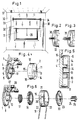
- a roller blind 32 is mounted on a room wall 30 in front of a window 31 by means of a left roller bracket 33 and a right roller bracket 34.
- This can be a spring-loaded roller blind that is pulled down by means of a handle 35, or a side-pull roller blind whose roller support 34 contains drive elements that are operated by means of a pull chain 36.
- the position of the roller blind supports in relation to the vertical direction and to the roller blind 32 depends on whether they are mounted on a wall 30 or (as also indicated in FIG. 1) on a ceiling 37 and on which roller blind side the roller blind supports is arranged.
- FIG. 2 shows the cylindrical roller blind pin 38 which can be rotatably arranged in a bearing shell of the roller blind carrier
- FIG. 3 illustrates a coupling pin 39 which is to be non-rotatably connected to a part of the roller blind carrier.
- roller blind carriers are fixedly mounted on the wall or ceiling before the roller blind is received, it is not possible to insert the two bearing journals 38, 39 in their longitudinal direction into the associated receiving opening of the roller blind carrier. Rather, only one of the two pins, for example pin 39, can be used approximately in the longitudinal direction of the associated receiving opening, while the second bearing pin has to reach the bearing shell receiving it by pivoting the roller blind around the first bearing pin in a lateral movement.
- the bearing bracket intended for receiving this second roller blind pin is first explained below with reference to FIGS. 4 and 5.
- the fastening part 1 has a flange 3 which is to be screwed to the wall or ceiling. It also comprises an arm 4 which is plate-like and at least partially round and which has a raised collar 5, the peripheral edge 6 of which contains a circumferential groove 7.
- the plate forming the arm also has a hollow cylindrical collar 9 which contains a cutout 10 at a circumferential point.
- the bearing part 2 consists of an end plate 11 and a jacket 12. In the middle of the end plate 11 there is the bearing shell 13, from which a slot 14 extends radially, which forms the insertion path through which a roller blind pin enters the bearing shell 13 from the side can be introduced.
- the inside diameter of the edge of the jacket 12 is equal to the outside diameter of the collar 5 and has a radially inwardly projecting ring projection 16 which engages in the annular groove 7 of the fastening part in the assembled state.
- a rotary bearing is formed for the bearing part 2 of the fastening part 1, which allows the bearing part 2 to be rotated relative to the fastening part.
- the roller blind pin 38 can be inserted into the slot 14 and the bearing shell 13 if the bearing part 2 has the setting shown in FIG. 1 with respect to the fastening part 1, in which the position of the slot 14 is included that of the cutout 10 in the collar 9 matches. If the bearing journal lies in the bearing shell 13 and thus also within the collar 9, the bearing part 2 is rotated so that the slot 14 points upwards, as shown in FIG. 2. The bearing shell 13 is then closed on its opening side formed by the slot 14 by the collar 9 and the bearing pin 38 therein secured.
- the two parts 1 and 2 can be fixed against rotation.
- This can be achieved in a simple manner in that the parts forming the pivot bearing 6, 7, 12, 16 are so matched to one another in their dimensions that rotation can only take place against considerable frictional force which is greater than that which is usually the case during the operation of a Twisting forces occurring in blinds.
- latching elements are preferably provided in the rotational positions usually used, through which the desired fixation takes place.
- These locking elements consist of interlocking elevations and depressions in the surfaces forming the pivot bearing.
- an elevation 8 is provided on the edge of the part 4, which adjoins the peripheral edge 6 of the collar 5, and the edge of the jacket 12 contains recesses 15 at corresponding points. that it ensures the desired locking effect in engagement with the recesses 15, but on the other hand, the parts forming the pivot bearing remain in engagement when the elevation 8 is not in a recess 15.
- the 6 comprises a fastening part 1, which is the same as that shown in FIGS. 1 and 2. It also includes known drive elements, which consist of a trailing spring 17, a sprocket 18, a chain 19 and a clutch disc 20.
- the collar 9 serves as a holder for the trailing spring 17, which is placed on the collar 9 in a conventional arrangement, the cutout 10 not interfering.
- the sprocket 18 and the chain 19 are of a conventional type.
- the clutch disc 20 is also the same as the prior art, unless further explained below.
- the jacket 21 is used to hold and support the drive elements.
- the clutch disc 20 is mounted and held therein. It contains openings 22 for the passage of the chain 19. These openings must be matched to the vertical direction in the installed position.
- the jacket 21 is rotationally connected to the fastening part 1 in the same way as was explained above with reference to FIGS. 4 and 5 for the bearing part 2, and corresponding latching elements 8, 15 can also be provided.
- the clutch disc 20 contains an adapter bore 23 for the rotationally secure reception of an adapter 24, which has the clutch bore 25 for cooperation with a roller blind coupling pin 39 of the same cross section.
- a plurality of such adapters 24, each with different cross-sectional shapes of the coupling bore 25, are provided for different blinds.
- this locking device is composed of a locking projection designed as a pin 28, which can subsequently be used in a bore in a thickening 27 of the fastening part 1, and bores 29 provided at a corresponding point in the jacket 21, several of which have circumferential dimensions according to FIGS possible settings are provided in practice.
- the pin 28 is inserted into the bores of the fastening part and the jacket.
Landscapes
- Structural Engineering (AREA)
- Engineering & Computer Science (AREA)
- Architecture (AREA)
- Civil Engineering (AREA)
- Operating, Guiding And Securing Of Roll- Type Closing Members (AREA)
- Blinds (AREA)
- Organic Low-Molecular-Weight Compounds And Preparation Thereof (AREA)
- Rolls And Other Rotary Bodies (AREA)
- Bridges Or Land Bridges (AREA)
- Secondary Cells (AREA)
- Measurement Of Length, Angles, Or The Like Using Electric Or Magnetic Means (AREA)
- Spinning Or Twisting Of Yarns (AREA)
- Forklifts And Lifting Vehicles (AREA)
- Building Awnings And Sunshades (AREA)
- Tents Or Canopies (AREA)
Priority Applications (1)
| Application Number | Priority Date | Filing Date | Title |
|---|---|---|---|
| AT88902124T ATE71180T1 (de) | 1987-02-28 | 1988-02-25 | Rollotrager. |
Applications Claiming Priority (2)
| Application Number | Priority Date | Filing Date | Title |
|---|---|---|---|
| DE8703112U DE8703112U1 (da) | 1987-02-28 | 1987-02-28 | |
| DE8703112U | 1987-02-28 |
Publications (2)
| Publication Number | Publication Date |
|---|---|
| EP0346377A1 EP0346377A1 (de) | 1989-12-20 |
| EP0346377B1 true EP0346377B1 (de) | 1992-01-02 |
Family
ID=6805342
Family Applications (1)
| Application Number | Title | Priority Date | Filing Date |
|---|---|---|---|
| EP88902124A Expired - Lifetime EP0346377B1 (de) | 1987-02-28 | 1988-02-25 | Rollotrager |
Country Status (9)
| Country | Link |
|---|---|
| US (1) | US5009259A (da) |
| EP (1) | EP0346377B1 (da) |
| AT (1) | ATE71180T1 (da) |
| DE (2) | DE8703112U1 (da) |
| DK (1) | DK168309B1 (da) |
| ES (1) | ES2009183A6 (da) |
| FI (1) | FI88196C (da) |
| NO (1) | NO170099C (da) |
| WO (1) | WO1988006672A1 (da) |
Families Citing this family (22)
| Publication number | Priority date | Publication date | Assignee | Title |
|---|---|---|---|---|
| AU606282B2 (en) * | 1988-06-16 | 1991-01-31 | Hunter Douglas Limited | Roller blind assembly |
| DE3927080C2 (de) * | 1989-08-17 | 1995-01-05 | Guenter Dipl Ing Lenze | Aufwickelvorrichtung |
| IT224916Z2 (it) * | 1990-01-26 | 1996-07-30 | Sunproject Srl | Dispositivo per il comando di un telo avvolgibile dall'esterno e/o dall'interno. |
| FR2664938B1 (fr) * | 1990-07-23 | 1992-10-23 | Somfy | Dispositif de fixation d'un moteur tubulaire pour l'entrainement d'un store ou analogues, dans une embrasure. |
| GB2246592A (en) * | 1990-08-02 | 1992-02-05 | Ventolite Nsb Limited | Roller mounting bracket |
| DE9210803U1 (da) * | 1992-08-12 | 1993-05-13 | Hwang, Chyi-Ming, Yung-Kang Shiang, Tainan, Tw | |
| ES2081785T3 (es) * | 1994-02-18 | 1997-06-16 | Imbac Spa | Soporte mejorado para elementos de maniobra de persianas enrollables. |
| US5482105A (en) * | 1994-05-12 | 1996-01-09 | General Clutch Corporation | Clutch control for roller shades |
| US5669432A (en) * | 1996-03-28 | 1997-09-23 | Nisenson; Jules | Automatic-locking mechanical drive construction |
| GB9609929D0 (en) * | 1996-05-13 | 1996-07-17 | Louver Lite Ltd | Roller blind |
| US5887637A (en) * | 1997-05-05 | 1999-03-30 | Phyper; Duncan | Aperture covering system |
| US5975186A (en) * | 1998-03-05 | 1999-11-02 | Day; Perry | Roller blinds mountings |
| DE50013324D1 (de) * | 1999-09-02 | 2006-09-28 | Dieter Prosch | Befestigungssystem für ein Bauelement, wie Wickelrolle oder Raffrolloträger an einer Trägerschiene für Fensterdekorationen |
| DK200001534A (da) * | 2000-10-13 | 2002-04-14 | Fabers Fab As C | En hæve- og sænkemekanisme, især til rullegradiner |
| KR100417618B1 (ko) * | 2001-03-07 | 2004-02-05 | 주식회사 홈네스터 | 다중 롤 블라인드 장치 |
| ATE455929T1 (de) * | 2002-03-12 | 2010-02-15 | Faber As | Befestigungsvorrichtung für rollos |
| WO2004101941A1 (en) * | 2003-05-14 | 2004-11-25 | Faber A/S | An adjustable mounting bracket for sun screens |
| US8122932B2 (en) | 2009-01-21 | 2012-02-28 | Rollease, Inc. | Multi-section window dressing with coupling clutch |
| US8695680B2 (en) | 2010-12-23 | 2014-04-15 | Rollease, Inc. | Disabling device for window treatment |
| GB201215667D0 (en) * | 2012-09-03 | 2012-10-17 | Louver Lite Ltd | Control assembly |
| EP3615760A2 (en) | 2017-04-28 | 2020-03-04 | Lutron Technology Company LLC | Window treatment mounting bracket |
| GB2588611B (en) | 2019-10-28 | 2021-11-24 | Fourds Ltd | A kit of parts for assembling a control assembly for a roller blind |
Family Cites Families (8)
| Publication number | Priority date | Publication date | Assignee | Title |
|---|---|---|---|---|
| GB191108877A (en) * | 1911-04-10 | 1912-04-10 | John Jesse James | Improvements in Curtain-rod and Analogous Brackets, and in the Production of the same. |
| US1379663A (en) * | 1920-02-04 | 1921-05-31 | Epifanio V N Tomasulo | Window-shade guard |
| US2487648A (en) * | 1946-08-10 | 1949-11-08 | Green Bella | Safety bracket for window shade rollers |
| NL171185C (nl) * | 1972-05-09 | 1983-02-16 | Hunter Douglas Ind Bv | Legerinrichting voor een rolgordijn of ander rolscherm. |
| NL156780B (nl) * | 1973-04-19 | 1978-05-16 | Silverflex Int Nv | Bevestigingsinrichting voor een rolgordijn of jaloezie. |
| DE2617502A1 (de) * | 1975-04-24 | 1976-11-04 | Theodor Willem Geitenbeek | Vorrichtung zum lagern von markisen o.dgl. |
| DE3211506A1 (de) * | 1982-03-29 | 1983-10-06 | Mhz Hachtel & Co | Rollo-wandtraeger und getriebe |
| DE3536160A1 (de) * | 1985-10-10 | 1987-04-23 | Starcke Zuendwarenfab | Seitenzugrollo |
-
1987
- 1987-02-28 DE DE8703112U patent/DE8703112U1/de not_active Expired
-
1988
- 1988-02-25 AT AT88902124T patent/ATE71180T1/de active
- 1988-02-25 US US07/399,494 patent/US5009259A/en not_active Expired - Fee Related
- 1988-02-25 DE DE8888902124T patent/DE3867465D1/de not_active Expired - Fee Related
- 1988-02-25 WO PCT/EP1988/000139 patent/WO1988006672A1/de active IP Right Grant
- 1988-02-25 EP EP88902124A patent/EP0346377B1/de not_active Expired - Lifetime
- 1988-02-26 ES ES8800573A patent/ES2009183A6/es not_active Expired
- 1988-10-26 NO NO884768A patent/NO170099C/no unknown
- 1988-10-27 DK DK598088A patent/DK168309B1/da not_active IP Right Cessation
-
1989
- 1989-08-22 FI FI893931A patent/FI88196C/fi not_active IP Right Cessation
Also Published As
| Publication number | Publication date |
|---|---|
| DK168309B1 (da) | 1994-03-07 |
| FI893931A0 (fi) | 1989-08-22 |
| NO170099C (no) | 1992-09-09 |
| FI88196C (fi) | 1993-04-13 |
| WO1988006672A1 (en) | 1988-09-07 |
| NO170099B (no) | 1992-06-01 |
| EP0346377A1 (de) | 1989-12-20 |
| ATE71180T1 (de) | 1992-01-15 |
| DK598088A (da) | 1988-10-27 |
| FI893931A (fi) | 1989-08-22 |
| DE3867465D1 (de) | 1992-02-13 |
| DK598088D0 (da) | 1988-10-27 |
| NO884768D0 (no) | 1988-10-26 |
| DE8703112U1 (da) | 1987-04-16 |
| US5009259A (en) | 1991-04-23 |
| NO884768L (no) | 1988-10-26 |
| FI88196B (fi) | 1992-12-31 |
| ES2009183A6 (es) | 1989-09-01 |
Similar Documents
| Publication | Publication Date | Title |
|---|---|---|
| EP0346377B1 (de) | Rollotrager | |
| DE4447366C2 (de) | Drehvorrichtung | |
| DE2517359C2 (de) | Kurbelbetätigtes Bandmaß | |
| DE1525381B1 (de) | Elastische kupplung fuer zwei im wesentlichen gleichachsige wellen | |
| DE602004000985T2 (de) | Schwenkbare Sitzstange | |
| DE10329959A1 (de) | Halter für einen Getränkebehälter | |
| DE3302312A1 (de) | Moebelscharnier | |
| DE19745933C1 (de) | Frischluft-Düseneinrichtung für ein Fahrzeug | |
| AT409881B (de) | Scharnier für ein flügelteil | |
| DE2819496C3 (de) | Vorrichtung zum Anbringen einer Dichtung am Rand einer Scheibe | |
| DE1652018A1 (de) | Gehaeuse fuer eine Schleifkammer | |
| DE60017694T2 (de) | Vorrichtung zum Fixieren eines Antriebs, und Betätigungsmechanismus einer Schliess- oder Sonnenschutzeinrichtung mit solcher Vorrichtung | |
| EP0467122B1 (de) | Bandzapfenbüchse | |
| DE1509481A1 (de) | Betaetigungsvorrichtung fuer eine Wendewelle einer Jalousie | |
| DE3150765A1 (de) | Befestigungsvorrichtung zur schwenkbaren befestigung eines gegenstands, insbesondere haltegriffs, an einer wand o.dgl. | |
| DE2845119A1 (de) | Stellvorrichtung fuer angelschnurrollen | |
| DE2359471A1 (de) | Schutzvorrichtung fuer fenster in form einer jalousie oder eines rolladens | |
| DE3033736C2 (da) | ||
| EP3574813B1 (de) | Scharnier für eine toilettensitzgarnitur | |
| EP2224091B1 (de) | Wendelager für Storen mit Lamellenelementen | |
| DE3050328T1 (da) | ||
| DE4121341A1 (de) | Schwenkvorrichtung fuer ein fernsehgeraet | |
| DE19724577C1 (de) | Lenkrolle | |
| DE2949042A1 (de) | Befestigungsanordnung fuer einen fahrzeugrueckblickspiegel | |
| DE10015186A1 (de) | Objektivfassung |
Legal Events
| Date | Code | Title | Description |
|---|---|---|---|
| PUAI | Public reference made under article 153(3) epc to a published international application that has entered the european phase |
Free format text: ORIGINAL CODE: 0009012 |
|
| AK | Designated contracting states |
Kind code of ref document: A1 Designated state(s): AT BE DE FR GB IT NL SE |
|
| 17P | Request for examination filed |
Effective date: 19890518 |
|
| RBV | Designated contracting states (corrected) |
Designated state(s): AT BE CH DE FR GB IT LI NL SE |
|
| 17Q | First examination report despatched |
Effective date: 19910218 |
|
| GRAA | (expected) grant |
Free format text: ORIGINAL CODE: 0009210 |
|
| AK | Designated contracting states |
Kind code of ref document: B1 Designated state(s): AT BE CH DE FR GB IT LI NL SE |
|
| REF | Corresponds to: |
Ref document number: 71180 Country of ref document: AT Date of ref document: 19920115 Kind code of ref document: T |
|
| REF | Corresponds to: |
Ref document number: 3867465 Country of ref document: DE Date of ref document: 19920213 |
|
| ITF | It: translation for a ep patent filed |
Owner name: UFFICIO TECNICO ING. A. MANNUCCI |
|
| ET | Fr: translation filed | ||
| GBT | Gb: translation of ep patent filed (gb section 77(6)(a)/1977) | ||
| PLBE | No opposition filed within time limit |
Free format text: ORIGINAL CODE: 0009261 |
|
| STAA | Information on the status of an ep patent application or granted ep patent |
Free format text: STATUS: NO OPPOSITION FILED WITHIN TIME LIMIT |
|
| 26N | No opposition filed | ||
| EAL | Se: european patent in force in sweden |
Ref document number: 88902124.2 |
|
| PGFP | Annual fee paid to national office [announced via postgrant information from national office to epo] |
Ref country code: GB Payment date: 19990105 Year of fee payment: 12 |
|
| PGFP | Annual fee paid to national office [announced via postgrant information from national office to epo] |
Ref country code: FR Payment date: 19990118 Year of fee payment: 12 |
|
| PGFP | Annual fee paid to national office [announced via postgrant information from national office to epo] |
Ref country code: SE Payment date: 19990218 Year of fee payment: 12 Ref country code: AT Payment date: 19990218 Year of fee payment: 12 |
|
| PGFP | Annual fee paid to national office [announced via postgrant information from national office to epo] |
Ref country code: BE Payment date: 19990219 Year of fee payment: 12 |
|
| PGFP | Annual fee paid to national office [announced via postgrant information from national office to epo] |
Ref country code: CH Payment date: 19990224 Year of fee payment: 12 |
|
| PGFP | Annual fee paid to national office [announced via postgrant information from national office to epo] |
Ref country code: NL Payment date: 19990228 Year of fee payment: 12 |
|
| PGFP | Annual fee paid to national office [announced via postgrant information from national office to epo] |
Ref country code: DE Payment date: 19990421 Year of fee payment: 12 |
|
| PG25 | Lapsed in a contracting state [announced via postgrant information from national office to epo] |
Ref country code: GB Free format text: LAPSE BECAUSE OF NON-PAYMENT OF DUE FEES Effective date: 20000225 Ref country code: AT Free format text: LAPSE BECAUSE OF NON-PAYMENT OF DUE FEES Effective date: 20000225 |
|
| PG25 | Lapsed in a contracting state [announced via postgrant information from national office to epo] |
Ref country code: SE Free format text: LAPSE BECAUSE OF NON-PAYMENT OF DUE FEES Effective date: 20000226 |
|
| PG25 | Lapsed in a contracting state [announced via postgrant information from national office to epo] |
Ref country code: BE Free format text: LAPSE BECAUSE OF NON-PAYMENT OF DUE FEES Effective date: 20000228 |
|
| PG25 | Lapsed in a contracting state [announced via postgrant information from national office to epo] |
Ref country code: LI Free format text: LAPSE BECAUSE OF NON-PAYMENT OF DUE FEES Effective date: 20000229 Ref country code: CH Free format text: LAPSE BECAUSE OF NON-PAYMENT OF DUE FEES Effective date: 20000229 |
|
| BERE | Be: lapsed |
Owner name: AEROLUX PRODUKTIONS- UND HANDELS G.M.B.H. Effective date: 20000228 |
|
| PG25 | Lapsed in a contracting state [announced via postgrant information from national office to epo] |
Ref country code: NL Free format text: LAPSE BECAUSE OF NON-PAYMENT OF DUE FEES Effective date: 20000901 |
|
| EUG | Se: european patent has lapsed |
Ref document number: 88902124.2 |
|
| REG | Reference to a national code |
Ref country code: CH Ref legal event code: PL |
|
| GBPC | Gb: european patent ceased through non-payment of renewal fee |
Effective date: 20000225 |
|
| PG25 | Lapsed in a contracting state [announced via postgrant information from national office to epo] |
Ref country code: FR Free format text: LAPSE BECAUSE OF NON-PAYMENT OF DUE FEES Effective date: 20001031 |
|
| NLV4 | Nl: lapsed or anulled due to non-payment of the annual fee |
Effective date: 20000901 |
|
| PG25 | Lapsed in a contracting state [announced via postgrant information from national office to epo] |
Ref country code: DE Free format text: LAPSE BECAUSE OF NON-PAYMENT OF DUE FEES Effective date: 20001201 |
|
| REG | Reference to a national code |
Ref country code: FR Ref legal event code: ST |
|
| PG25 | Lapsed in a contracting state [announced via postgrant information from national office to epo] |
Ref country code: IT Free format text: LAPSE BECAUSE OF NON-PAYMENT OF DUE FEES;WARNING: LAPSES OF ITALIAN PATENTS WITH EFFECTIVE DATE BEFORE 2007 MAY HAVE OCCURRED AT ANY TIME BEFORE 2007. THE CORRECT EFFECTIVE DATE MAY BE DIFFERENT FROM THE ONE RECORDED. Effective date: 20050225 |