EP0343948A2 - Elektrophotographisches Druckgerät - Google Patents
Elektrophotographisches Druckgerät Download PDFInfo
- Publication number
- EP0343948A2 EP0343948A2 EP89305235A EP89305235A EP0343948A2 EP 0343948 A2 EP0343948 A2 EP 0343948A2 EP 89305235 A EP89305235 A EP 89305235A EP 89305235 A EP89305235 A EP 89305235A EP 0343948 A2 EP0343948 A2 EP 0343948A2
- Authority
- EP
- European Patent Office
- Prior art keywords
- forms
- photosensitive drum
- drum
- fan
- fold
- Prior art date
- Legal status (The legal status is an assumption and is not a legal conclusion. Google has not performed a legal analysis and makes no representation as to the accuracy of the status listed.)
- Granted
Links
Images

Classifications
-
- G—PHYSICS
- G03—PHOTOGRAPHY; CINEMATOGRAPHY; ANALOGOUS TECHNIQUES USING WAVES OTHER THAN OPTICAL WAVES; ELECTROGRAPHY; HOLOGRAPHY
- G03G—ELECTROGRAPHY; ELECTROPHOTOGRAPHY; MAGNETOGRAPHY
- G03G15/00—Apparatus for electrographic processes using a charge pattern
- G03G15/65—Apparatus which relate to the handling of copy material
- G03G15/6517—Apparatus for continuous web copy material of plain paper, e.g. supply rolls; Roll holders therefor
- G03G15/6526—Computer form folded [CFF] continuous web, e.g. having sprocket holes or perforations
-
- G—PHYSICS
- G03—PHOTOGRAPHY; CINEMATOGRAPHY; ANALOGOUS TECHNIQUES USING WAVES OTHER THAN OPTICAL WAVES; ELECTROGRAPHY; HOLOGRAPHY
- G03G—ELECTROGRAPHY; ELECTROPHOTOGRAPHY; MAGNETOGRAPHY
- G03G15/00—Apparatus for electrographic processes using a charge pattern
- G03G15/14—Apparatus for electrographic processes using a charge pattern for transferring a pattern to a second base
- G03G15/16—Apparatus for electrographic processes using a charge pattern for transferring a pattern to a second base of a toner pattern, e.g. a powder pattern, e.g. magnetic transfer
- G03G15/163—Apparatus for electrographic processes using a charge pattern for transferring a pattern to a second base of a toner pattern, e.g. a powder pattern, e.g. magnetic transfer using the force produced by an electrostatic transfer field formed between the second base and the electrographic recording member, e.g. transfer through an air gap
- G03G15/1635—Apparatus for electrographic processes using a charge pattern for transferring a pattern to a second base of a toner pattern, e.g. a powder pattern, e.g. magnetic transfer using the force produced by an electrostatic transfer field formed between the second base and the electrographic recording member, e.g. transfer through an air gap the field being produced by laying down an electrostatic charge behind the base or the recording member, e.g. by a corona device
- G03G15/164—Apparatus for electrographic processes using a charge pattern for transferring a pattern to a second base of a toner pattern, e.g. a powder pattern, e.g. magnetic transfer using the force produced by an electrostatic transfer field formed between the second base and the electrographic recording member, e.g. transfer through an air gap the field being produced by laying down an electrostatic charge behind the base or the recording member, e.g. by a corona device the second base being a continuous paper band, e.g. a CFF
-
- G—PHYSICS
- G03—PHOTOGRAPHY; CINEMATOGRAPHY; ANALOGOUS TECHNIQUES USING WAVES OTHER THAN OPTICAL WAVES; ELECTROGRAPHY; HOLOGRAPHY
- G03G—ELECTROGRAPHY; ELECTROPHOTOGRAPHY; MAGNETOGRAPHY
- G03G15/00—Apparatus for electrographic processes using a charge pattern
- G03G15/65—Apparatus which relate to the handling of copy material
- G03G15/6552—Means for discharging uncollated sheet copy material, e.g. discharging rollers, exit trays
-
- G—PHYSICS
- G03—PHOTOGRAPHY; CINEMATOGRAPHY; ANALOGOUS TECHNIQUES USING WAVES OTHER THAN OPTICAL WAVES; ELECTROGRAPHY; HOLOGRAPHY
- G03G—ELECTROGRAPHY; ELECTROPHOTOGRAPHY; MAGNETOGRAPHY
- G03G2215/00—Apparatus for electrophotographic processes
- G03G2215/00362—Apparatus for electrophotographic processes relating to the copy medium handling
- G03G2215/00367—The feeding path segment where particular handling of the copy medium occurs, segments being adjacent and non-overlapping. Each segment is identified by the most downstream point in the segment, so that for instance the segment labelled "Fixing device" is referring to the path between the "Transfer device" and the "Fixing device"
- G03G2215/00371—General use over the entire feeding path
-
- G—PHYSICS
- G03—PHOTOGRAPHY; CINEMATOGRAPHY; ANALOGOUS TECHNIQUES USING WAVES OTHER THAN OPTICAL WAVES; ELECTROGRAPHY; HOLOGRAPHY
- G03G—ELECTROGRAPHY; ELECTROPHOTOGRAPHY; MAGNETOGRAPHY
- G03G2215/00—Apparatus for electrophotographic processes
- G03G2215/00362—Apparatus for electrophotographic processes relating to the copy medium handling
- G03G2215/00367—The feeding path segment where particular handling of the copy medium occurs, segments being adjacent and non-overlapping. Each segment is identified by the most downstream point in the segment, so that for instance the segment labelled "Fixing device" is referring to the path between the "Transfer device" and the "Fixing device"
- G03G2215/00409—Transfer device
-
- G—PHYSICS
- G03—PHOTOGRAPHY; CINEMATOGRAPHY; ANALOGOUS TECHNIQUES USING WAVES OTHER THAN OPTICAL WAVES; ELECTROGRAPHY; HOLOGRAPHY
- G03G—ELECTROGRAPHY; ELECTROPHOTOGRAPHY; MAGNETOGRAPHY
- G03G2215/00—Apparatus for electrophotographic processes
- G03G2215/00362—Apparatus for electrophotographic processes relating to the copy medium handling
- G03G2215/00367—The feeding path segment where particular handling of the copy medium occurs, segments being adjacent and non-overlapping. Each segment is identified by the most downstream point in the segment, so that for instance the segment labelled "Fixing device" is referring to the path between the "Transfer device" and the "Fixing device"
- G03G2215/00417—Post-fixing device
- G03G2215/00421—Discharging tray, e.g. devices stabilising the quality of the copy medium, postfixing-treatment, inverting, sorting
-
- G—PHYSICS
- G03—PHOTOGRAPHY; CINEMATOGRAPHY; ANALOGOUS TECHNIQUES USING WAVES OTHER THAN OPTICAL WAVES; ELECTROGRAPHY; HOLOGRAPHY
- G03G—ELECTROGRAPHY; ELECTROPHOTOGRAPHY; MAGNETOGRAPHY
- G03G2215/00—Apparatus for electrophotographic processes
- G03G2215/00362—Apparatus for electrophotographic processes relating to the copy medium handling
- G03G2215/00443—Copy medium
- G03G2215/00447—Plural types handled
-
- G—PHYSICS
- G03—PHOTOGRAPHY; CINEMATOGRAPHY; ANALOGOUS TECHNIQUES USING WAVES OTHER THAN OPTICAL WAVES; ELECTROGRAPHY; HOLOGRAPHY
- G03G—ELECTROGRAPHY; ELECTROPHOTOGRAPHY; MAGNETOGRAPHY
- G03G2215/00—Apparatus for electrophotographic processes
- G03G2215/00362—Apparatus for electrophotographic processes relating to the copy medium handling
- G03G2215/00443—Copy medium
- G03G2215/00451—Paper
- G03G2215/00455—Continuous web, i.e. roll
- G03G2215/00459—Fan fold, e.g. CFF, normally perforated
-
- G—PHYSICS
- G03—PHOTOGRAPHY; CINEMATOGRAPHY; ANALOGOUS TECHNIQUES USING WAVES OTHER THAN OPTICAL WAVES; ELECTROGRAPHY; HOLOGRAPHY
- G03G—ELECTROGRAPHY; ELECTROPHOTOGRAPHY; MAGNETOGRAPHY
- G03G2215/00—Apparatus for electrophotographic processes
- G03G2215/00362—Apparatus for electrophotographic processes relating to the copy medium handling
- G03G2215/00535—Stable handling of copy medium
- G03G2215/00544—Openable part of feed path
Definitions
- This invention relates to an electrophotographic printer for selectively feeding fan-fold forms and cut sheets and for printing on optionally selected forms.
- this invention relates to an electrophotographic printer which features a mechanism for handling both types of forms within the printer.
- Electrophotographic printers are generally constituted to operate as single-function printers which use cut sheets or fan-fold forms.
- This invention seeks to provide a printer for selectively printing on both cut sheets and fan-fold forms, wherein the components can be used in common to a great extent.
- the printer is required to handle each form within the printer to meet the requirements for printing on each form.
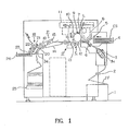
- the invention provides an electrophotographic printer comprising a photosensitive drum; a form feeder having means for feeding cut sheets to said photosensitive drum and means for feeding fan-fold forms to said photosensitive drum, both means being provided in parallel adjacent to said photosensitive drum; a frame capable of being driven towards said photosensitive drum to allow forms fed by said form feeder to make contact with said photosensitive drum; means provided on said frame for transferring images on said photosensitive drum to the forms in contact with said drum; a conveyor belt for sucking forms from said transfer means with a suction pressure to convey said forms; means for fixing transferred images on the forms conveyed by said conveyor belt; and means for discharging the forms from the fixing means.
- a stocker 1 of fan-fold forms FF is installed on the bottom (bottom right in Figure 1) of the printer body M.
- An EOF sensor 2 for detecting the end of the forms is installed on the feeding path of the forms FF.
- a tractor 3 for conveying the forms FF to the transfer section C described later, is also installed on the feeding path of the fan-fold forms.
- the tractor 3 is provided with pins 3a on the surface of the belt at the same pitch as the sprocket holes perforated on both edges of the fan-fold forms.
- the fan-fold form feeding path is composed of components 1 to 3 and guide plates to the location immediately before the transfer section C.
- a cassette 4 for cut sheets CS is installed on the printer body M above the fan-fold form stocker 1; a pick-up roller 5 is installed on the outlet of the cassette 4; and an alignment roller 6 for correcting skewing, is installed in the feeding path for cut sheets CS after the pick-up roller 5.
- the cut sheet feeding path is composed of components 4 to 6 and guide plates to the location immediately before the transfer section C.
- a photosensitive drum 7 is installed after the end of and above the form paths.
- a developing means consisting of a toner feeder 8, a charger 9 and a cleaner 10, and these are arranged so as to allow a laser beam L from a laser optical system 11 to radiate the outer surface of the drum 7.
- the drum 7 is driven by a motor with controllable speed including stop, such as a stepping motor (not shown).
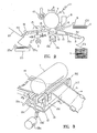
- the frame 13, either right side or left side, is mounted so as to pivot on a shaft 13a parallel to and below the drum 7 and deviated from the center line of the drum 7, and the bottom of the frame 13 is supported by an eccentric cam 13b.
- the gaps between the lower surface of the drum 7 and the upper surfaces of gap adjusting guides 13d, 13e provided before and after the transfer corotron 12 in the frame 13 is adjusted according to the type of form.
- the cam 13b is driven by a motor whose angle of rotation can be controlled, such as a stepping motor 13c.
- the transfer section C is constituted of components from the photosensitive drum 7 through gap adjusting guides 13d, 13e.
- a conveyor belt 14 in the fixing section P where images transferred to the forms are fixed there are a conveyor belt 14 in the fixing section P where images transferred to the forms are fixed, and a fuser unit 15 mainly consisting of flash lamps.
- a fuser unit 15 mainly consisting of flash lamps.
- another conveyor belt 16 is used before the conveyor belt 14 in the fixing section P in the embodiment shown in Figure 1, this belt 16 is not essential, and is optionally installed depending on the length of the form paths.
- the conveyor belt 14 or 16 adjacent to the drum 7 is provided with a suction means 17 for sucking the forms passing through the transfer section C to prevent electrostatic attraction of the forms by the drum 7.
- a separating corotron 13g is installed before the conveyor belt 14 or 16 in the vicinity of the drum 7 (see Figures 3 through 6).
- a form discharging means 18 is installed after the front end of the conveyor belt 14 in the fixing section P, and is composed, in this embodiment, of a discharging puller 19 which takes the forms into the discharging paths, a first flapper 20 which branches the discharging paths for cut sheets CS and fan-fold forms FF, a second flapper 21 which sends cut sheets CS to an accompanying reversing means 22, a discharging roller 23, and a stacker puller 24.
- Stackers 25 and 26 are installed below exits for the respective forms.
- the stacker 25 has paddles 25a.
- the printer outlined above is provided with unique mechanisms as described below in order to handle cut sheets and fan-fold forms of different thickness and conveying conditions without trouble in the same transfer section C and fixing section P.
- the forms are subjected to tension because the discharging puller 19, which takes the forms into the form discharging means 18, is driven slightly faster than the tractor 3.
- the optimal distance between the drum 7 and the retractable frame 13 is approximately 0.5 mm, and the larger distance affects contact of the drum 7 and the forms FF and lowers transfer efficiency.
- the optimal distance between the drum 7 and the transfer corotron 12 on the frame 13 is approximately 0.8 mm, and a smaller distance may cause conveying trouble such as jamming. If the distance between the drum 7 and the transfer corotron 12 on the frame 13 is too wide, contact of the drum 7 and the forms CS is affected causing poor transfer, particularly when thick forms are used.
- This invention aims at solving the above problems in prior art printers, and provides an efficient transfer mechanism for printing on both continuous and cut sheets without conveying trouble.
- a motor 13c whose angle of rotation can be controlled, such as a stepping motor, for controlling the position of the frame 13 so that an adequate distance between the drum 7 and the transfer corotron 12 for both the fan-fold forms FF and cut sheets CS is obtained.
- the forms are then conveyed by the conveyor belt 14, and after the toner on the forms is fixed by the flash light in the fixing section P, the forms are discharged through the form discharging path to a stacker 26 by a discharging puller 19.
- the frame 13 of the transfer corotron 12 is placed on the eccentric cam 13b fixed to the output shaft of the stepping motor 13c, and is elevated or lowered around the shaft 13a by the rotation of the motor 13c.
- the distance between the drum 7 and the upper surface of the frame 13 can be changed by elevating or lowering the frame 13 relative to the drum 7.
- the relationship between the angle of rotation of the stepping motor 13c and the upper surface of the transfer corotron 12 is, for example, as follows.
- the stepping motor 13c When printing is not performed, the stepping motor 13c is excited to a phase angle of 0° (the lower dead point of the eccentric cam), and the distance between the photosensitive drum 7 and the frame 13 becomes the maximum.
- the motor 13c When cut sheets are used, the motor 13c is excited to rotate 143° , and the distance between the drum 7 and the frame 13 is maintained at about 0.8 mm.
- the motor 13c When fan-fold forms are used, the motor 13c is excited to rotate 180° (the upper dead point of the eccentric cam), and the distance between the drum 7 and the frame 13 is maintained at about 0.5 mm.
- the printer since the distance between the photosensitive drum 7 and the transfer corotron 12 on the frame 13, which guides the forms can be set to an appropriate value for either fan-fold forms FF or cut sheets CS, the printer, with little form conveying trouble, can be constituted without lowering transfer capacity.
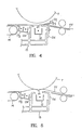
- the frame 13 is moved to the vicinity of the photosensitive drum 7 when printing is started on fan-fold forms FF, as shown in Figure 3 by the action of the motor 13c and a link 13b′, equivalent to the cam 13b of Figure 2, and allows the forms to approach the photosensitive drum 7.
- the toner on the drum 7 is transferred on to the forms by the corona discharge of the transfer corotron 12, and synchronizing the stop of printing, the frame 13 is retracted below the drum and functions to separate the forms from the drum 7.
- the conventional retractable frame 13 was provided with guides 13d and 13e before and after the transfer corotron 12, respectively. These guides 13d, 13e were used for allowing the forms to contact with the drum 7 during printing, and were so adjusted that both the distance between the guide 13d and the drum 7 and the distance between the guide 13e and the drum 7 are equally about 0.5 - 0.8 mm.
- the gap between guides 13d, 13e and the drum 7 of 0.5 - 0.8 mm may cause jamming of the forms because it is difficult for the end of a form to enter into the gap.
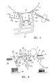
- forms conveyed by guides 13d, 13e are allowed to contact the drum 7 by making the distance between the guide 13e in the exit side of the transfer section C and the drum 7 larger than the distance between the guide 13d in the inlet side of the transfer section C and the drum 7.
- the front (right-hand side in Figure 6) guide 13d faces the drum 7 with a gap of about 0.8 mm.
- the guide 13e on the exit side faces the drum 7 with a gap of about 1.2 mm.
- Both guides 13d, 13e are supported so that the tangent at point A on the drum 7 is flush with the upper surfaces of these guides 13d, 13e.
- the printer having form guides in the transfer section C as shown in Figures 3 and 6 has the following problems when fan-fold forms FF are used.
- toner on the drum 7 is transferred on to desired pages of the fan-fold forms FF by corona discharge of the transfer corotron 12.
- the frame 13 of the transfer corotron 12 is retracted downward away from the drum 7 by the action of the cam 13b or the link 13b′, and the forms are separated from the drum 7.
- a form presser guide 13f is provided above the inlet guide 13d to the frame 13 of the transfer corotron 12 so as to press the form from the top.
- the presser guide 13f is fixed to the guide 13d of the frame 13 to maintain a gap through which the forms pass. Therefore, the presser guide 13f is moved upward or downward when printing is started or stopped while maintaining the gap l between the presser guide 13f and the upper surface of the guide 13d of the frame 13.
- Figure 4 is a cross-sectional view showing a printing stop condition.
- the frame 13 is retracted away from the drum 7, since the presser guide 13f presses the form FF from the top, the sagging of the form is avoided resulting in the contact of the form FF with the drum 7 which causes contamination of the form by the toner.
- the gap l between the upper surface of the guide 13d of the frame 13 and the presser guide 13f must be at least wide enough to enable a form of the maximum thickness usable in the printer to pass.
- the gap is preferably 0.2 - 0.5 mm.
- the fan-fold forms are restricted by the tractor 3 and the discharging puller 19. That is, the puller 19 is driven at a peripheral speed several percent faster than the feed speed of the tractor 3 to apply tension to the fan-fold forms so as not to produce creases or sagging during printing.
- the fan-fold form is cut using a cutter (not shown) for discharging.
- the optimal value of the peripheral speed of the discharging puller 19 and the speed of the conveyor belt 14 should be set to differ for fan-fold forms FF and cut-sheet forms CS.
- the form conveying speed is equal to the peripheral speeds of the feeder roll 6, the photosensitive drum 7, discharging puller 19, and the speed of the conveyor belt 14 at each location. Therefore, the adequate speed of the conveyor belt 14 and the discharging puller 19 are equal to, or at greatest, 2% higher than the form conveying speed. If these speeds are higher, the form conveying speed becomes higher than the peripheral speed of the photosensitive drum and printed images are stretched, causing poor printing.
- a speed controllable motor 18a such as a stepping motor, is used as the drive power source for the discharging puller 19 and the conveyor belt 14 in common with the drive for the discharging means 18 but independent from other drive power sources for conveying.
- the motor 18a is controlled to achieve the adequate speed of the discharging puller 19 and the conveyor belt 14 for both fan-fold forms FF and cut-sheet forms CS, as Figure 7 shows.
- the control section (not shown) of the printer determines whether the form is the fan-fold form or the cut-sheet form, and controls the motor 18a to achieve optimal speed of the discharging puller 19 and the conveyor belt 14 for each form.
- reference 18b indicates a transmission belt.
- the peripheral speed of the drum 7 should be slightly lower than the form conveying speed considering the tolerances of components such as the outer diameter of the photosensitive drum.
- the form conveying speed is equal to the speed of the feed roll 6, photosensitive drum 7, conveyor belt 14 and discharging puller 19 at each location, and difference from the peripheral speed of the drum 7 directly affects the extension or contraction of the printed image. Therefore, the peripheral speed of the photosensitive drum 7 should be set to be exactly equal to the standard form conveying speed.
- the printer is arranged to ensure an optimum feed speed in the transfer section C for both fan-fold form FF and cut-sheet form CS so as to obtain good print quality.
- Excellent feed speed can be obtained for both the fan-fold and the cut-sheet form by varying the speed of the photosensitive drum 7, and provision is made to use a motor, the speed of which can be controlled, such as a stepping motor in the driving source (not shown) of the photosensitive drum 7 separately from that for other form conveyor mechanism to control the speed of the photosensitive drum 7 so that the optimum form conveyor speed can be obtained both in printing the fan-fold form and in printing the cut-sheet form.
- a motor the speed of which can be controlled, such as a stepping motor in the driving source (not shown) of the photosensitive drum 7 separately from that for other form conveyor mechanism to control the speed of the photosensitive drum 7 so that the optimum form conveyor speed can be obtained both in printing the fan-fold form and in printing the cut-sheet form.
- the photosensitive drum 7 to have the driver section independent from that of the other form conveyor mechanism, and enables it to be independently controlled, so that, although not shown, the control section of the printer can determine whether printing is for the fan-fold form or the cut-sheet form when it receives a print start instruction from the host controller, and control drive of the motor, which is the driving source of the photosensitive drum 7, to obtain a photosensitive drum speed most suitable for each form.
- the printer with the above-mentioned arrangement is designed to separate the form, which is electrostatically attached to the drum 7, from the drum surface with a conveyor belt 14 after the toner on the drum 7 is transferred to the form, to feed it to the fixing section P where the toner on the form is fixed to the form by the flash light from the fuser unit 15.
- the conveyor belt 14 causes a sucking force, by suction pressure, to act on the bottom surface of the form to separate the form from the surface of the drum 7, and to convey it to a location below the fuser unit 15 in the fixing section P.
- Such a suction mechanism may cause improper conveying to occur because, when the cut-sheet form is separated from the drum 7, insufficient suction pressure during feeding of the cut-sheet forms may cause a cut-sheet form to slip on the conveyor belt 14, or a curled and warped sheet to abut other components.
- a change-over flapper 20 in the form discharging path is directed downward at its front end in the printing of the cut-sheet form, and the suction pressure is adjusted to about 250 mm of water (2.45 x 10³ Pa) by an adjusting cock 17b.
- the solenoid valve 17a is closed. Because the cut-sheet form is closely attached to and carried on the conveyor belt 14, there is no possibility of defective conveyance, such as slipping of the cut-sheet form on the conveyor belt 14 when it is separated from the surface of the drum 7, sharing of the toner when the toner on the surface of the drum 7 is transferred to the form, or abutting of the curled form against other components.
- the change-over flapper 20 is directed upward at its front end in the printing of the fan-fold form.
- the suction pressure is adjusted to about 150 mm of water (1.48 x 10³ Pa) by an adjusting cock 17c through opening of the solenoid valve 17a.
- the fan-fold form is maintained at a proper form tension of 800 g between the tractor 3 and the discharging puller 19, and the conveyor belt 14.
- the load acting on the conveyor belt 14 is no different from that in the printing of the cut-sheet form, and therefore, the driving torque of the conveyor belt 14 is maintained at about 3 kg-cm.
- the suction mechanism according to the above arrangement can separately adjust the suction pressure to the proper value for printing either the fan-fold form or the cut-sheet form so that, in feeding the cut-sheet form, it will adhere firmly to the conveyor belt 14. Therefore, sharing of the toner on the cut-sheet form and defective conveyance of the form can be effectively prevented.
- the suction pressure at a low level required for its proper conveyance
- the load acting on the conveyor belt 14 can be maintained at a low level so that the driving mechanism such as the stepping motor 18a for driving the belt 14 and the like, and the driver for controlling the motor can be made small in size and inexpensive.
- reducing the load acting on the driving section also reduces the amount of wear on the driving section and the aging. Therefore, it is possible to prevent the problem of the stepping motor becoming out of step by a load increase caused by aging.
- both the cut-sheet and the fan-fold forms are selectively printed through the transfer section C of the single configuration, and the fixing section P, and conveyed to the form discharging mechanism 18 by the conveyor belt 14 in the fixing portion P.
- each printed form being conveyed is discharged to respective stackers 25 and 26, depending on the type of the forms.
- the path for the cut-sheet form branched by the second flapper 21 located far from the transfer section C is divided into a face-up side and a face-down side of the cut-sheet form to cause the form to run in its respective path.
- independent stacking areas are provided for the printed fan-fold form FF and the cut-sheet form CS so that changing-over of the operation of printing between the fan-fold form and the cut-sheet form can be quickly accommodated, while the stacking tray can be shared for the stacking position of the fan-fold form FF and for the cut-sheet form CS that is discharged by the face-up/face-down function.
- the printed fan-fold form FF is fed into the form discharging mechanism 18 by the discharging puller 19 through the fixing section P.
- the form FF runs under the bottom of the flapper, is fed out on the stacker 25 by a stacker puller 24, and stacked while being arranged by a paddle 25a.
- the printed cut-sheet form CS goes to the path for the cut-sheet form indicated by an arrow a.
- the orientation of the cut-sheet form CS is determined by the action of the second flapper 21, which changes the face-up and the face-down of the cut-sheet form CS, in response to an instruction from a controller (not shown), and follows the determined path.
- the cut-sheet form CS advances to the path at the side of the form reversing means 22, and is stacked on the cut-sheet form tray 26 with its printed surface down through the reversing roller 22a, the reversing plate 22b and the feed-out roller 23.
- the cut-sheet form CS advances straight as it is, and is stacked on the cut-sheet form tray 26 with its printed surface up through the feed roller 23′ and the feed-out roller 23.
- the fan-fold form FF and the cut-sheet form CS are selectively printed while sharing the transfer section C and the fixing section P, and then, stacked on the stacker 25 and the cut-sheet form tray 26, respectively. Therefore, for example, once the fan-fold form FF is cut by a cutter immediately after its printing, and discharged onto its stacker 25, printing of the cut-sheet form CS can be started immediately.
- the fan-fold form FF is still loaded on the tractor 3, because an operation opposite to the above can be performed, it is possible to improve the availability factor per printer.
- the fan-fold form FF is arranged to be discharged below the path change-over section according to the first flapper 20, and stacked, the printed fan-fold form FF can be stored at the lower portion of the printing mechanism with good space efficiency. This allows the overall floor space occupied by the printer and the access area of the operator to be reduced.
- the reversing means 22 for the cut-sheet form is arranged by positioning the reversing plate 22b over the form discharging mechanism 18 with an angle as the path for face-down forms, designing the reversing of the form in a switch-back method with good space efficiency, and forming in a shape with a large curvature allowing smooth reversing or passing of a thick cut-sheet form CS with a greater stiffness.
- the reversing means 22 can be mounted compactly in the machine, and can reverse even a thick form in a good condition for stacking.
- the same tray 26 is arranged to be shared by the cut-sheet form in both the face-up and the face-down state, it is possible to make the machine compact, and to integrate handling of printed forms.
Landscapes
- Physics & Mathematics (AREA)
- General Physics & Mathematics (AREA)
- Engineering & Computer Science (AREA)
- General Engineering & Computer Science (AREA)
- Handling Of Sheets (AREA)
- Electrostatic Charge, Transfer And Separation In Electrography (AREA)
- Handling Of Continuous Sheets Of Paper (AREA)
- Control Or Security For Electrophotography (AREA)
- Paper Feeding For Electrophotography (AREA)
Applications Claiming Priority (2)
| Application Number | Priority Date | Filing Date | Title |
|---|---|---|---|
| JP126019/88 | 1988-05-25 | ||
| JP63126019A JPH07110546B2 (ja) | 1988-05-25 | 1988-05-25 | 電子写真方式の印刷装置 |
Publications (3)
| Publication Number | Publication Date |
|---|---|
| EP0343948A2 true EP0343948A2 (de) | 1989-11-29 |
| EP0343948A3 EP0343948A3 (en) | 1990-01-03 |
| EP0343948B1 EP0343948B1 (de) | 1993-02-10 |
Family
ID=14924704
Family Applications (1)
| Application Number | Title | Priority Date | Filing Date |
|---|---|---|---|
| EP89305235A Expired - Lifetime EP0343948B1 (de) | 1988-05-25 | 1989-05-24 | Elektrophotographisches Druckgerät |
Country Status (5)
| Country | Link |
|---|---|
| US (1) | US4929982A (de) |
| EP (1) | EP0343948B1 (de) |
| JP (1) | JPH07110546B2 (de) |
| CA (1) | CA1322020C (de) |
| DE (1) | DE68904810T2 (de) |
Cited By (7)
| Publication number | Priority date | Publication date | Assignee | Title |
|---|---|---|---|---|
| GB2242865A (en) * | 1990-04-13 | 1991-10-16 | Asahi Optical Co Ltd | Skew prevention structure for electrophotographic printer |
| EP0469164A1 (de) * | 1990-07-30 | 1992-02-05 | Toray Industries, Inc. | Elektrophotographisches Druckgerät |
| EP0582741A1 (de) * | 1992-08-12 | 1994-02-16 | Toray Industries, Inc. | Elektrofotografisches Gerät und Verfahren |
| EP0555884A3 (en) * | 1992-02-13 | 1994-10-05 | Mita Industrial Co Ltd | A parallel transport apparatus |
| EP0713157A1 (de) * | 1992-08-12 | 1996-05-22 | Toray Industries, Inc. | Vorrichtung und Verfahren zum Drucken |
| WO2014012341A1 (zh) * | 2012-07-19 | 2014-01-23 | Li Huarong | 一体化双通道数码印刷设备 |
| IT201800006573A1 (it) * | 2018-06-21 | 2019-12-21 | Stazione di alimentazione per un’apparecchiatura per la lavorazione di fogli e/o nastri |
Families Citing this family (17)
| Publication number | Priority date | Publication date | Assignee | Title |
|---|---|---|---|---|
| US5113228A (en) * | 1990-02-09 | 1992-05-12 | Asahi Kogaku Kogyo Kabushiki Kaisha | Sheet separating mechanism |
| US5155539A (en) * | 1990-06-07 | 1992-10-13 | Asahi Kogaku Kogyo Kabushiki Kaisha | Sheet separating mechanism |
| JP3034006B2 (ja) * | 1990-10-13 | 2000-04-17 | 旭光学工業株式会社 | 連続記録紙を用いる電子写真プリンタ |
| JP2728799B2 (ja) * | 1991-04-06 | 1998-03-18 | 東レ株式会社 | プリンタの用紙搬送方法 |
| JPH04321062A (ja) * | 1991-04-22 | 1992-11-11 | Hitachi Koki Co Ltd | 連続印刷用紙の両面印刷装置 |
| JP2575107Y2 (ja) * | 1991-08-23 | 1998-06-25 | 旭光学工業株式会社 | 連続記録紙を用いるプリンタの記録紙搬送機構 |
| USRE36112E (en) * | 1992-08-14 | 1999-02-23 | Toray Industries, Inc. | Electrophotographic apparatus capable of selectively using cut sheet and continuous paper and method therefor |
| JP2961472B2 (ja) * | 1992-10-22 | 1999-10-12 | 三田工業株式会社 | トナー像転写手段を備えた画像生成機 |
| DE4404636B4 (de) * | 1993-02-18 | 2007-02-22 | Fuji Xerox Co., Ltd. | Abbildungsvorrichtung |
| JP2824008B2 (ja) * | 1993-02-26 | 1998-11-11 | 富士通株式会社 | 電子写真式連続紙印刷装置 |
| JP2691686B2 (ja) * | 1993-03-19 | 1997-12-17 | 富士通株式会社 | 連続用紙を用いる像形成装置 |
| US5875383A (en) * | 1997-09-30 | 1999-02-23 | Xerox Corporation | Dual mode interchangeable modules cut sheet or web printing system with a single xerographic cut sheet print engine |
| US5970304A (en) * | 1997-09-30 | 1999-10-19 | Xerox Corporation | Two sided imaging of a continuous web substrate with a single print engine with in line transfer stations |
| US7167673B2 (en) * | 2004-06-23 | 2007-01-23 | Lexmark International, Inc. | Method and apparatus for using continuous media stock in a cut-sheet image forming device |
| JP2006227422A (ja) * | 2005-02-18 | 2006-08-31 | Fuji Xerox Co Ltd | 画像形成装置 |
| JP5039296B2 (ja) * | 2005-11-02 | 2012-10-03 | 株式会社リコー | 画像形成装置 |
| JP6106950B2 (ja) * | 2011-05-27 | 2017-04-05 | 株式会社リコー | 画像形成装置 |
Family Cites Families (18)
| Publication number | Priority date | Publication date | Assignee | Title |
|---|---|---|---|---|
| US3893760A (en) * | 1973-07-16 | 1975-07-08 | Xerox Corp | Transfer apparatus |
| JPS5497041A (en) * | 1978-01-17 | 1979-07-31 | Konishiroku Photo Ind Co Ltd | Zerographic copier |
| JPS5588086A (en) * | 1978-12-26 | 1980-07-03 | Canon Inc | Transfer device |
| US4191467A (en) * | 1979-04-04 | 1980-03-04 | Xerox Corporation | Dual mode catch tray |
| EP0024154B1 (de) * | 1979-08-21 | 1983-08-24 | Roneo Alcatel Limited | Papierzuführung und Bildübertragung für elektrostatographische Kopier- und Vervielfältigungsapparate |
| JPS5685764A (en) * | 1979-12-13 | 1981-07-13 | Ricoh Co Ltd | Gap maintaining device of electrostatic recorder |
| JPS5730866A (en) * | 1980-08-01 | 1982-02-19 | Ricoh Co Ltd | Separating device for transfer material of copying machine |
| JPS58126544A (ja) * | 1981-12-23 | 1983-07-28 | Toshiba Corp | 画像形成装置におけるコロナ放電装置 |
| US4408866A (en) * | 1982-03-01 | 1983-10-11 | Eastman Kodak Company | Receiver sheet transport with alignment means |
| JPS5938770A (ja) * | 1982-08-27 | 1984-03-02 | Fuji Xerox Co Ltd | 剥離コロトロン |
| JPS59177575A (ja) * | 1983-03-29 | 1984-10-08 | Ricoh Co Ltd | 複写装置 |
| JPS608052U (ja) * | 1983-06-29 | 1985-01-21 | 富士通株式会社 | 記録装置 |
| JPS6015472A (ja) * | 1983-07-06 | 1985-01-26 | Nippon Sheet Glass Co Ltd | コ−テイング組成物 |
| US4699496A (en) * | 1985-08-30 | 1987-10-13 | Siemens Aktiengesellschaft | Contact pressure mechanism for a web-shaped image receiving material |
| US4714946A (en) * | 1985-11-27 | 1987-12-22 | International Business Machines Corporation | Continuous form feeder for a reproducing machine and process |
| JPS62290668A (ja) * | 1986-06-06 | 1987-12-17 | Minolta Camera Co Ltd | シ−ト搬送装置 |
| JPS63315451A (ja) * | 1987-01-17 | 1988-12-23 | Asahi Optical Co Ltd | 電子写真用被記録媒体供給方法 |
| US4843429A (en) * | 1988-04-29 | 1989-06-27 | International Business Machines Corporation | Method and apparatus for printing near page boundaries |
-
1988
- 1988-05-25 JP JP63126019A patent/JPH07110546B2/ja not_active Expired - Fee Related
-
1989
- 1989-05-18 US US07/353,846 patent/US4929982A/en not_active Expired - Lifetime
- 1989-05-24 DE DE8989305235T patent/DE68904810T2/de not_active Expired - Fee Related
- 1989-05-24 EP EP89305235A patent/EP0343948B1/de not_active Expired - Lifetime
- 1989-05-25 CA CA000600653A patent/CA1322020C/en not_active Expired - Fee Related
Cited By (10)
| Publication number | Priority date | Publication date | Assignee | Title |
|---|---|---|---|---|
| GB2242865A (en) * | 1990-04-13 | 1991-10-16 | Asahi Optical Co Ltd | Skew prevention structure for electrophotographic printer |
| US5317371A (en) * | 1990-04-13 | 1994-05-31 | Asahi Kogaku Kogyo Kabushiki Kaisha | Skew prevention structure for electrophotographic printer |
| GB2242865B (en) * | 1990-04-13 | 1994-11-02 | Asahi Optical Co Ltd | Skew prevention structure for electrophotographic printer |
| EP0469164A1 (de) * | 1990-07-30 | 1992-02-05 | Toray Industries, Inc. | Elektrophotographisches Druckgerät |
| EP0555884A3 (en) * | 1992-02-13 | 1994-10-05 | Mita Industrial Co Ltd | A parallel transport apparatus |
| EP0582741A1 (de) * | 1992-08-12 | 1994-02-16 | Toray Industries, Inc. | Elektrofotografisches Gerät und Verfahren |
| EP0713157A1 (de) * | 1992-08-12 | 1996-05-22 | Toray Industries, Inc. | Vorrichtung und Verfahren zum Drucken |
| WO2014012341A1 (zh) * | 2012-07-19 | 2014-01-23 | Li Huarong | 一体化双通道数码印刷设备 |
| IT201800006573A1 (it) * | 2018-06-21 | 2019-12-21 | Stazione di alimentazione per un’apparecchiatura per la lavorazione di fogli e/o nastri | |
| WO2019244041A1 (en) * | 2018-06-21 | 2019-12-26 | HUNKELER.IT S.r.l. | Feeding station for an apparatus for processing sheets and/or webs |
Also Published As
| Publication number | Publication date |
|---|---|
| CA1322020C (en) | 1993-09-07 |
| JPH07110546B2 (ja) | 1995-11-29 |
| DE68904810T2 (de) | 1993-08-19 |
| US4929982A (en) | 1990-05-29 |
| JPH01306268A (ja) | 1989-12-11 |
| EP0343948B1 (de) | 1993-02-10 |
| DE68904810D1 (de) | 1993-03-25 |
| EP0343948A3 (en) | 1990-01-03 |
Similar Documents
| Publication | Publication Date | Title |
|---|---|---|
| EP0343948B1 (de) | Elektrophotographisches Druckgerät | |
| USRE45207E1 (en) | Sheet treating apparatus and image forming apparatus therewith | |
| JP2003327364A (ja) | 画像形成装置 | |
| JP3257712B2 (ja) | 搬送路切換装置 | |
| JP4115206B2 (ja) | 画像形成装置 | |
| CN1321870C (zh) | 纸张处理装置及纸张处理方法 | |
| JP7168432B2 (ja) | シート積載装置及び画像形成システム | |
| JP3149139B2 (ja) | 給紙装置 | |
| JPH04308147A (ja) | シート材搬送経路の構造 | |
| JP2017149501A (ja) | シート処理装置及び画像形成システム | |
| JPH1072159A (ja) | 用紙搬送装置および用紙搬送方法 | |
| JP7240158B2 (ja) | シート積載装置及び画像形成システム | |
| EP4215467B1 (de) | Blattnachbearbeitungsvorrichtung und entsprechendes bilderzeugungssystem | |
| JP2002308502A (ja) | 画像形成装置 | |
| JP3178599B2 (ja) | 画像形成装置 | |
| US5895139A (en) | Image forming device with a printer unit and a copying unit | |
| JP2669995B2 (ja) | シート後処理装置 | |
| JP2967200B2 (ja) | 自動原稿送り装置 | |
| JP2941368B2 (ja) | 用紙収納トレイの幅合わせ装置 | |
| JP2926416B2 (ja) | 原稿自動送り装置 | |
| JP2007076895A (ja) | シート後処理装置 | |
| JP2001088946A (ja) | 画像形成装置の両面ユニット | |
| JP3556144B2 (ja) | 給紙装置 | |
| JP3581494B2 (ja) | シート材処理装置及び画像形成装置 | |
| JPH10330012A (ja) | プリンタ、スタッカユニット及びスタッカユニットを含むプリンタ |
Legal Events
| Date | Code | Title | Description |
|---|---|---|---|
| PUAI | Public reference made under article 153(3) epc to a published international application that has entered the european phase |
Free format text: ORIGINAL CODE: 0009012 |
|
| PUAL | Search report despatched |
Free format text: ORIGINAL CODE: 0009013 |
|
| AK | Designated contracting states |
Kind code of ref document: A2 Designated state(s): DE FR GB IT |
|
| AK | Designated contracting states |
Kind code of ref document: A3 Designated state(s): DE FR GB IT |
|
| 17P | Request for examination filed |
Effective date: 19900326 |
|
| 17Q | First examination report despatched |
Effective date: 19920115 |
|
| GRAA | (expected) grant |
Free format text: ORIGINAL CODE: 0009210 |
|
| AK | Designated contracting states |
Kind code of ref document: B1 Designated state(s): DE FR GB IT |
|
| PG25 | Lapsed in a contracting state [announced via postgrant information from national office to epo] |
Ref country code: IT Free format text: LAPSE BECAUSE OF FAILURE TO SUBMIT A TRANSLATION OF THE DESCRIPTION OR TO PAY THE FEE WITHIN THE PRESCRIBED TIME-LIMIT;WARNING: LAPSES OF ITALIAN PATENTS WITH EFFECTIVE DATE BEFORE 2007 MAY HAVE OCCURRED AT ANY TIME BEFORE 2007. THE CORRECT EFFECTIVE DATE MAY BE DIFFERENT FROM THE ONE RECORDED. Effective date: 19930210 |
|
| REF | Corresponds to: |
Ref document number: 68904810 Country of ref document: DE Date of ref document: 19930325 |
|
| ET | Fr: translation filed | ||
| PLBE | No opposition filed within time limit |
Free format text: ORIGINAL CODE: 0009261 |
|
| STAA | Information on the status of an ep patent application or granted ep patent |
Free format text: STATUS: NO OPPOSITION FILED WITHIN TIME LIMIT |
|
| 26N | No opposition filed | ||
| REG | Reference to a national code |
Ref country code: GB Ref legal event code: IF02 |
|
| PGFP | Annual fee paid to national office [announced via postgrant information from national office to epo] |
Ref country code: FR Payment date: 20020516 Year of fee payment: 14 |
|
| PGFP | Annual fee paid to national office [announced via postgrant information from national office to epo] |
Ref country code: GB Payment date: 20030502 Year of fee payment: 15 |
|
| PGFP | Annual fee paid to national office [announced via postgrant information from national office to epo] |
Ref country code: DE Payment date: 20030528 Year of fee payment: 15 |
|
| PG25 | Lapsed in a contracting state [announced via postgrant information from national office to epo] |
Ref country code: FR Free format text: LAPSE BECAUSE OF NON-PAYMENT OF DUE FEES Effective date: 20040130 |
|
| REG | Reference to a national code |
Ref country code: FR Ref legal event code: ST |
|
| PG25 | Lapsed in a contracting state [announced via postgrant information from national office to epo] |
Ref country code: GB Free format text: LAPSE BECAUSE OF NON-PAYMENT OF DUE FEES Effective date: 20040524 |
|
| PG25 | Lapsed in a contracting state [announced via postgrant information from national office to epo] |
Ref country code: DE Free format text: LAPSE BECAUSE OF NON-PAYMENT OF DUE FEES Effective date: 20041201 |
|
| GBPC | Gb: european patent ceased through non-payment of renewal fee |
Effective date: 20040524 |