EP0340167A2 - Procédé pour plier des piecès à usiner - Google Patents
Procédé pour plier des piecès à usiner Download PDFInfo
- Publication number
- EP0340167A2 EP0340167A2 EP89810290A EP89810290A EP0340167A2 EP 0340167 A2 EP0340167 A2 EP 0340167A2 EP 89810290 A EP89810290 A EP 89810290A EP 89810290 A EP89810290 A EP 89810290A EP 0340167 A2 EP0340167 A2 EP 0340167A2
- Authority
- EP
- European Patent Office
- Prior art keywords
- angle
- bending
- workpiece
- die
- punch
- Prior art date
- Legal status (The legal status is an assumption and is not a legal conclusion. Google has not performed a legal analysis and makes no representation as to the accuracy of the status listed.)
- Withdrawn
Links
Images
Classifications
-
- B—PERFORMING OPERATIONS; TRANSPORTING
- B21—MECHANICAL METAL-WORKING WITHOUT ESSENTIALLY REMOVING MATERIAL; PUNCHING METAL
- B21D—WORKING OR PROCESSING OF SHEET METAL OR METAL TUBES, RODS OR PROFILES WITHOUT ESSENTIALLY REMOVING MATERIAL; PUNCHING METAL
- B21D5/00—Bending sheet metal along straight lines, e.g. to form simple curves
- B21D5/02—Bending sheet metal along straight lines, e.g. to form simple curves on press brakes without making use of clamping means
- B21D5/0209—Tools therefor
- B21D5/0236—Tool clamping
Definitions
- the invention relates to a method for bending a workpiece according to a given desired angle.
- the method is carried out with the aid of a bending device which has a bending punch and a bending die which has a die base which is adjustable in accordance with the angle to be formed.
- the bending angle can be theoretically calculated precisely by determining the depth of penetration of the bending punch into the die for a given width of the die, but the theoretical values cannot be achieved practically, since the actual bending angle, depending on the accuracy of the punch feed into the die, and Quality and thickness of the sheet metal piece to be bent, minor or major deviations from the target value.
- a bending device in which the bending angle can be set and changed very easily and precisely, brings a certain improvement.
- Such bending devices expediently have a bending die which has an adjustable die bottom.
- the bending angle can be exactly determined and changed without changing the die by adjusting or changing the height of the die bottom.
- the bending die points to it, the bending punch facing side on a longitudinal groove, which determines the current bending angle by the relative position of the two fixed contact edges delimiting the groove opening and the movable groove base. In this case, too, a springback occurs when the workpiece is unloaded, so that the actual bending angle does not match the theoretical, calculated value.
- an angle measuring device which has a support element that can be placed against the workpiece to be measured at a first point, and a pivoting head that can be pivotally connected to the support element and can be placed against the piece of sheet metal to be measured at a point away from the first contact point .
- the connection of the contact points of the support element and the probe with the workpiece define the current angular position of the workpiece.
- An angle measuring element is provided for detecting the pivoting movement of the probe.
- the actual sheet metal angle can be determined continuously and precisely, so that a deviation from the target value can be precisely determined at each angular position.
- Another measure that contributes to improving the accuracy during the bending process consists in preventing or compensating for deformation of the elements of the bending machine that are primarily involved in the pressing process in order to avoid inaccurate machining of the workpiece.
- the applicant has already proposed to use a bending stamp, the stamp holder rests on a support element which ver vertically in a holding part is slidable and supported on an oil cushion. It is advantageous if the oil cushion is covered with a membrane on which the support element then rests.
- the applicant has already further proposed to use a bending die in which the support beam is divided several times along its length, so that beam parts which are guided vertically displaceably are present independently of one another.
- a bending device which has an elastically supported bending punch and a bending die with a die base which can be adjusted according to the angle to be formed.
- the work piece can be relieved in the second operation in an advantageous manner by reducing the pressure in the elastic support of the punch.
- the full load of the ram in the last step takes place by increasing the fluid pressure in the elastic support. In this way, a simple, reliable and precise procedure is made possible, which allows the exact maintenance of a given sheet angle.
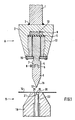
- FIG. 1 of the accompanying drawings is a suitable bend Device for performing the method shown schematically in vertical section.
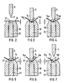
- 2-7 show schematic cross-sectional sketches through punch, sheet metal and die during different phases of the bending process according to the invention.
- the bending device basically consists of a vertically movable upper tool A and a fixed lower tool B.
- the upper tool A is provided with a carrier 1, which is arranged on the movable bar of a press brake in a known manner.
- a connecting member 2 is fastened to the beam 1 of the bar by a welded connection 3, the connecting member 2 having a slot-like recess which extends essentially over the entire width of the connecting member and into which a punch holder 4 projects.
- the punch holder 4 is provided with a bending punch 5 which is used directly for bending a workpiece, e.g. a piece of sheet metal 14 is used.
- the stamp 5 is fastened in the stamp holder 4 by means of an extension 6 which engages in a corresponding groove 7 in the stamp holder 4 and is held there with clamping members 8.
- a membrane holder 12 which is supported against a holding flange 15, serves to hold the membrane 11 in place.
- the channel-like depression is filled with liquid 13, for example filled with pressure oil, the arrangement being such that the liquid pressure can be increased and decreased by known means, for example by a corresponding pump, not shown in the drawing.
- the bending punch 5 has a working edge 17 where the two working surfaces 16 of the punch 5 collide at an angle that is smaller than the smallest angle that can be produced with this tool.
- the lower tool B has a die body 18 which is equipped with a longitudinal groove 19 on its surface facing the punch 5. This longitudinal groove determines the bending angle by the relative position of the two contact edges 20 delimiting the groove opening and by the depth of the groove base 21.
- the flat longitudinal groove 19 is arranged in the vertical longitudinal center plane of the die body 18 and is adjustable Floor 21 equipped.
- the groove base 21 is formed, for example, by pins 22 acting as supports, which are inserted in vertical openings of the die body 18 arranged next to one another and are guided displaceably in these openings.
- the upper end faces of the pins 22 form the groove bottom 21.
- the pin ends facing away from the groove base 21 rest in a known manner on a stop bar, not shown, which is adjustable on an inclined surface and thus enables the groove base 21 to be raised or lowered precisely.
- the piece of sheet metal 14 to be deformed rests on the die body 18.
- the groove base 21 is first brought into a position in which the base together with the support edges 20 determines an angle which is greater than the setpoint angle.
- the sheet metal piece 14 is pressed against the groove bottom 21 with the help of the working edge 17.
- This preload is released by relieving the sheet metal piece 14, the relieving being carried out by withdrawing the bending punch 5.
- the adjustable groove base 22 is in a first position, in which the surface 21 of the groove base 22 is at a distance a below the surface of the die body 18. This position a corresponds to a specific bending angle ⁇ , which is somewhat larger than the predetermined bending angle ⁇ to be actually achieved.
- the pre-bent sheet 14 is then relieved by, for example, pulling back the bending punch 5 somewhat.
- the bent sheet springs back somewhat, so that the angle ⁇ ′ enclosed by the two legs 14a and 14b is somewhat larger than the theoretical bending angle ⁇ .
- This springback can be observed in practically all types of sheet and the size of the springback depends on the material and quality of the sheet, its thickness, etc.
- the effective angle ⁇ ' is measured, which is present when the sheet 14 is relieved. This can be done with the angle measuring device mentioned at the beginning.
- the size of the angle is known and the difference ( ⁇ ′ - ⁇ ) is formed.
- the position b of the die base 22 is known, in which the sheet would be bent exactly at an angle ⁇ .
- the springback rate ( ⁇ ′ - ⁇ ) is known. From this, the definitive position (b + ⁇ b) of the die base 21 can be calculated, in which the sheet 14 will ultimately have exactly the desired bend.
- the die base 22 is shifted into a second position, in which the surface 21 is at a distance (b + ⁇ b) from the surface of the die body 18.
- the amount of (b + ⁇ b) is slightly larger than the amount of a, corresponding to a smaller, resulting bending angle.
- the punch 5 is again pushed against the die 18 until the leading edge of the sheet metal bend touches the surface 21 of the die bottom 22, and then stopped.
- This situation is shown in Fig. 6.
- the two legs 14a and 14b of the sheet 14 include an angle ⁇ ', which is slightly smaller than the desired bending angle ⁇ .
- the sheet 14 After the sheet 14 has been relieved, e.g. by retracting the punch 5 (FIG. 7), the sheet 14 springs back somewhat in order to finally have the desired bending angle ⁇ .
- the first bending takes place at an angle of approximately 91 °, that is to say an angle which is certainly somewhat larger than the ultimately desired angle.
- the two legs spring back somewhat so that they now enclose an angle of 93 °. The difference is therefore 2 °.
- the die base is adjusted so much that after the second bend a bending angle of 88 ° results with the sheet loaded. If the sheet is relieved after the second bending operation, the two legs spring back by 1 ° each, with the result that the bending angle is exactly the desired 90 °.
Landscapes
- Engineering & Computer Science (AREA)
- Mechanical Engineering (AREA)
- Bending Of Plates, Rods, And Pipes (AREA)
Applications Claiming Priority (2)
| Application Number | Priority Date | Filing Date | Title |
|---|---|---|---|
| AT0104688A AT390575B (de) | 1988-04-25 | 1988-04-25 | Verfahren zum biegen eines werkstueckes |
| AT1046/88 | 1988-04-25 |
Publications (2)
| Publication Number | Publication Date |
|---|---|
| EP0340167A2 true EP0340167A2 (fr) | 1989-11-02 |
| EP0340167A3 EP0340167A3 (fr) | 1990-10-24 |
Family
ID=3505415
Family Applications (1)
| Application Number | Title | Priority Date | Filing Date |
|---|---|---|---|
| EP19890810290 Withdrawn EP0340167A3 (fr) | 1988-04-25 | 1989-04-18 | Procédé pour plier des piecès à usiner |
Country Status (4)
| Country | Link |
|---|---|
| US (1) | US4966029A (fr) |
| EP (1) | EP0340167A3 (fr) |
| JP (1) | JP2694617B2 (fr) |
| AT (1) | AT390575B (fr) |
Cited By (1)
| Publication number | Priority date | Publication date | Assignee | Title |
|---|---|---|---|---|
| WO2013116888A1 (fr) * | 2012-02-10 | 2013-08-15 | Trumpf Maschinen Austria Gmbh & Co. Kg. | Table de presse ou poutre de presse présentant un élément poutre réglable |
Families Citing this family (14)
| Publication number | Priority date | Publication date | Assignee | Title |
|---|---|---|---|---|
| JPH072088Y2 (ja) * | 1988-11-15 | 1995-01-25 | 株式会社小松製作所 | 曲げ機械の工具位置制御装置 |
| US5365767A (en) * | 1992-03-23 | 1994-11-22 | Steelcase Inc. | Brake press arrangement |
| US5408858A (en) * | 1994-01-24 | 1995-04-25 | Amada Engineering & Service Co., Inc. | Bending machine utilizing controlled expandable pressure device to apply uniform pressure to work material |
| DE69529526T2 (de) * | 1994-07-08 | 2003-11-06 | Amada Co., Ltd. | Verfahren zum biegen mit einer abkantpresse und abkantpresse zum ausführen dieses verfahrens |
| DE19519108C2 (de) * | 1995-05-24 | 1999-03-25 | Knupfer Metallverarb Gmbh | Verfahren und Vorrichtung zur Messung von Winkeln, insbesondere von Biegewinkeln von Blechteilen |
| US6026573A (en) * | 1997-05-14 | 2000-02-22 | Dana Corporation | Method for manufacturing a side rail for a vehicle frame assembly |
| IT1311827B1 (it) * | 1999-04-16 | 2002-03-19 | Luciano Gasparini | Forchetta a forcella del tipo basculante autocentrante,particolarmente per la misurazione su quattro punti dell'angolo di |
| WO2003095122A1 (fr) * | 2002-05-08 | 2003-11-20 | Flow Holdings Sagl | Dispositif et procede de formage par expansion |
| US20070056348A1 (en) * | 2005-09-09 | 2007-03-15 | David Leland | Brake punch inserts |
| CN103406403B (zh) * | 2013-08-01 | 2015-05-13 | 江苏鹏诚钢构有限公司 | 一种压力平弯装置 |
| CN104056881B (zh) * | 2013-10-17 | 2016-02-17 | 攀钢集团攀枝花钢铁研究院有限公司 | 金属板材弯曲装置 |
| JP6846267B2 (ja) * | 2017-04-04 | 2021-03-24 | 株式会社アマダ | 下型装置及びワークの折曲げ加工方法 |
| EP3991869B1 (fr) * | 2019-06-28 | 2025-11-12 | Kawasaki Jukogyo Kabushiki Kaisha | Frein à presse et procédé pour actionner un frein à presse |
| CN117548532B (zh) * | 2024-01-11 | 2024-04-05 | 沈阳华铁异型材有限公司 | 一种铁包条折弯装置及其折弯方法 |
Family Cites Families (19)
| Publication number | Priority date | Publication date | Assignee | Title |
|---|---|---|---|---|
| US3552182A (en) * | 1968-11-20 | 1971-01-05 | Wisconsin Machine Corp | Press brake with hydraulic ram adjustment |
| US3760622A (en) * | 1972-02-01 | 1973-09-25 | I Mansell | Elastomeric forming die |
| AT311152B (de) * | 1972-04-13 | 1973-11-12 | Haemmerle Ag Maschf | Biegewerkzeug |
| AT311153B (de) * | 1972-04-13 | 1973-11-12 | Haemmerle Ag Maschf | Blechbearbeitungseinrichtung |
| JPS5311273B2 (fr) * | 1973-12-27 | 1978-04-20 | ||
| US3978706A (en) * | 1974-12-24 | 1976-09-07 | Nippon Kokan Kabushiki Kaisha | Precision bending work method for metallic materials |
| NL179349C (nl) * | 1975-06-24 | Haemmerle Ag Maschf | Buigwerktuig. | |
| IT1072273B (it) * | 1977-02-01 | 1985-04-10 | Selecontrol Sas | Dispositivo per la rilevazione e regolazione di angoli di piega particolarmente adatto per presse-piegatrici |
| JPS54417A (en) * | 1977-06-03 | 1979-01-05 | Hayashigumi Kk | Method of construction of pressing in presssin pipe |
| DE2952108C2 (de) * | 1979-12-22 | 1983-11-24 | Hämmerle AG, Zofingen | Anordnung zur Höhenverstellung des Matrizenbodens von Biegewerkzeugen zum Biegen von Blechen |
| JPS57202928A (en) * | 1981-06-08 | 1982-12-13 | Amada Co Ltd | Bender |
| CH655874A5 (de) * | 1982-06-07 | 1986-05-30 | Haemmerle Ag Maschf | Werkzeugeinrichtung an einer abkantpresse. |
| JPS5992120A (ja) * | 1982-11-15 | 1984-05-28 | Hitachi Ltd | 曲げ加工装置 |
| EP0166351A3 (fr) * | 1984-06-27 | 1986-09-17 | Arnold Stucki | Dispositif pour une machine de travail de déformation des tôles |
| AT381251B (de) * | 1984-10-18 | 1986-09-25 | Haemmerle Ag | Verfahren zur korrektur des biegewinkels beim blechbiegen mit einem biegestempel |
| JPS61129522A (ja) * | 1984-11-29 | 1986-06-17 | Hitachi Ltd | 曲げ角度検出・補正・加工方法 |
| JPS61229421A (ja) * | 1985-04-03 | 1986-10-13 | Mitsubishi Heavy Ind Ltd | 板状物の曲げ加工方法 |
| US4802357A (en) * | 1987-05-28 | 1989-02-07 | The Boeing Company | Apparatus and method of compensating for springback in a workpiece |
| US4864509A (en) * | 1987-09-29 | 1989-09-05 | The Boeing Company | Method and related apparatus for controlling the operation of a press brake |
-
1988
- 1988-04-25 AT AT0104688A patent/AT390575B/de active
-
1989
- 1989-04-14 US US07/339,074 patent/US4966029A/en not_active Expired - Lifetime
- 1989-04-18 EP EP19890810290 patent/EP0340167A3/fr not_active Withdrawn
- 1989-04-24 JP JP1104365A patent/JP2694617B2/ja not_active Expired - Lifetime
Cited By (4)
| Publication number | Priority date | Publication date | Assignee | Title |
|---|---|---|---|---|
| WO2013116888A1 (fr) * | 2012-02-10 | 2013-08-15 | Trumpf Maschinen Austria Gmbh & Co. Kg. | Table de presse ou poutre de presse présentant un élément poutre réglable |
| CN104203445A (zh) * | 2012-02-10 | 2014-12-10 | 特鲁普机械奥地利有限公司及两合公司 | 包括可调节的梁元件的挤压台或挤压梁 |
| US9381558B2 (en) | 2012-02-10 | 2016-07-05 | Trumpf Maschinen Austria Gmbh & Co. Kg. | Press table or press beam having adjustable beam element |
| CN104203445B (zh) * | 2012-02-10 | 2016-11-23 | 特鲁普机械奥地利有限公司及两合公司 | 包括可调节的梁元件的挤压台或挤压梁 |
Also Published As
| Publication number | Publication date |
|---|---|
| JPH01313112A (ja) | 1989-12-18 |
| ATA104688A (de) | 1989-11-15 |
| AT390575B (de) | 1990-05-25 |
| EP0340167A3 (fr) | 1990-10-24 |
| US4966029A (en) | 1990-10-30 |
| JP2694617B2 (ja) | 1997-12-24 |
Similar Documents
| Publication | Publication Date | Title |
|---|---|---|
| EP0340167A2 (fr) | Procédé pour plier des piecès à usiner | |
| EP0341211B1 (fr) | Procédé de pliage de tôle | |
| DE29623800U1 (de) | Bearbeitungsmaschine zum Abkanten von Werkstücken | |
| EP0096278B1 (fr) | Procédé de pliage de tôle et dispositif pour la mise en oeuvre dudit procédé | |
| DE102012013371B4 (de) | Messvorrichtung für ein Stößelkissen einer Presse | |
| DE3120093A1 (de) | Nietmaschine, insbesondere zum aufnieten der bremsbelaege auf den belagtraeger von bremsbacken | |
| EP1793946A1 (fr) | Procede pour realiser une piece par cintrage | |
| EP2548668B1 (fr) | Procédé pour le dressage automatique de pièces allongées par torsion | |
| EP3155366B1 (fr) | Outil d'étalonnage d'un outil de mesure d'angle dans un poinçon de pliage et procédé d'étalonnage de l'outil de mesure d'angle | |
| AT512465B1 (de) | Presstisch oder pressbalken mit verstellbarem balkenelement | |
| AT511711B1 (de) | Fertigungseinrichtung mit biegewerkzeugen und positionierungsmittel | |
| WO2020207645A1 (fr) | Procédé et dispositif de mesure servant à mesurer ou à étalonner des ustensiles de presses | |
| AT381251B (de) | Verfahren zur korrektur des biegewinkels beim blechbiegen mit einem biegestempel | |
| DE1292112B (de) | Vorrichtung zum Einstanzen von Nietmuttern in Blechwerkstuecke | |
| CH695668A5 (de) | Mess- und Steuervorrichtung in einer Abkantfpresse. | |
| DE3735015A1 (de) | Richtpresse | |
| DE3245753A1 (de) | Verfahren zum einstellen eines masshaltigen eintauchweges des oberwerkzeuges einer biegepresse, insbesondere abkantpresse | |
| DE2805206C2 (de) | Abbiegewerkzeug zum Herstellen U-förmiger Werkstücke | |
| EP0492193A1 (fr) | Procédé et appareil pour insérer une broche dans une plaque mince | |
| DE1502706B2 (de) | Blechbearbeitungsmaschine, insbesondere tafelschere | |
| DE1193337B (de) | Werkzeugmaschine mit einem aus einer Ausnehmung ihres Staenders herausschiebbaren Tragarm | |
| DE9100459U1 (de) | Vorrichtung zum Setzen von selbstbohrenden Schrauben in einen harten Untergrund | |
| EP0003476B1 (fr) | Outil de cintrage pour la fabrication de pièces en forme de U | |
| EP0128342B1 (fr) | Presse avec un dispositif pour l'éjection des pièces et un dispositif pour l'ajustage de l'altitude de fermeture | |
| DE252317C (fr) |
Legal Events
| Date | Code | Title | Description |
|---|---|---|---|
| PUAI | Public reference made under article 153(3) epc to a published international application that has entered the european phase |
Free format text: ORIGINAL CODE: 0009012 |
|
| AK | Designated contracting states |
Kind code of ref document: A2 Designated state(s): BE CH DE ES FR GB IT LI LU NL SE |
|
| PUAL | Search report despatched |
Free format text: ORIGINAL CODE: 0009013 |
|
| AK | Designated contracting states |
Kind code of ref document: A3 Designated state(s): BE CH DE ES FR GB IT LI LU NL SE |
|
| 17P | Request for examination filed |
Effective date: 19901122 |
|
| 17Q | First examination report despatched |
Effective date: 19920731 |
|
| STAA | Information on the status of an ep patent application or granted ep patent |
Free format text: STATUS: THE APPLICATION IS DEEMED TO BE WITHDRAWN |
|
| 18D | Application deemed to be withdrawn |
Effective date: 19921211 |