EP0340167A2 - Method of bending work pieces - Google Patents
Method of bending work pieces Download PDFInfo
- Publication number
- EP0340167A2 EP0340167A2 EP89810290A EP89810290A EP0340167A2 EP 0340167 A2 EP0340167 A2 EP 0340167A2 EP 89810290 A EP89810290 A EP 89810290A EP 89810290 A EP89810290 A EP 89810290A EP 0340167 A2 EP0340167 A2 EP 0340167A2
- Authority
- EP
- European Patent Office
- Prior art keywords
- angle
- bending
- workpiece
- die
- punch
- Prior art date
- Legal status (The legal status is an assumption and is not a legal conclusion. Google has not performed a legal analysis and makes no representation as to the accuracy of the status listed.)
- Withdrawn
Links
Images
Classifications
-
- B—PERFORMING OPERATIONS; TRANSPORTING
- B21—MECHANICAL METAL-WORKING WITHOUT ESSENTIALLY REMOVING MATERIAL; PUNCHING METAL
- B21D—WORKING OR PROCESSING OF SHEET METAL OR METAL TUBES, RODS OR PROFILES WITHOUT ESSENTIALLY REMOVING MATERIAL; PUNCHING METAL
- B21D5/00—Bending sheet metal along straight lines, e.g. to form simple curves
- B21D5/02—Bending sheet metal along straight lines, e.g. to form simple curves on press brakes without making use of clamping means
- B21D5/0209—Tools therefor
- B21D5/0236—Tool clamping
Definitions
- the invention relates to a method for bending a workpiece according to a given desired angle.
- the method is carried out with the aid of a bending device which has a bending punch and a bending die which has a die base which is adjustable in accordance with the angle to be formed.
- the bending angle can be theoretically calculated precisely by determining the depth of penetration of the bending punch into the die for a given width of the die, but the theoretical values cannot be achieved practically, since the actual bending angle, depending on the accuracy of the punch feed into the die, and Quality and thickness of the sheet metal piece to be bent, minor or major deviations from the target value.
- a bending device in which the bending angle can be set and changed very easily and precisely, brings a certain improvement.
- Such bending devices expediently have a bending die which has an adjustable die bottom.
- the bending angle can be exactly determined and changed without changing the die by adjusting or changing the height of the die bottom.
- the bending die points to it, the bending punch facing side on a longitudinal groove, which determines the current bending angle by the relative position of the two fixed contact edges delimiting the groove opening and the movable groove base. In this case, too, a springback occurs when the workpiece is unloaded, so that the actual bending angle does not match the theoretical, calculated value.
- an angle measuring device which has a support element that can be placed against the workpiece to be measured at a first point, and a pivoting head that can be pivotally connected to the support element and can be placed against the piece of sheet metal to be measured at a point away from the first contact point .
- the connection of the contact points of the support element and the probe with the workpiece define the current angular position of the workpiece.
- An angle measuring element is provided for detecting the pivoting movement of the probe.
- the actual sheet metal angle can be determined continuously and precisely, so that a deviation from the target value can be precisely determined at each angular position.
- Another measure that contributes to improving the accuracy during the bending process consists in preventing or compensating for deformation of the elements of the bending machine that are primarily involved in the pressing process in order to avoid inaccurate machining of the workpiece.
- the applicant has already proposed to use a bending stamp, the stamp holder rests on a support element which ver vertically in a holding part is slidable and supported on an oil cushion. It is advantageous if the oil cushion is covered with a membrane on which the support element then rests.
- the applicant has already further proposed to use a bending die in which the support beam is divided several times along its length, so that beam parts which are guided vertically displaceably are present independently of one another.
- a bending device which has an elastically supported bending punch and a bending die with a die base which can be adjusted according to the angle to be formed.
- the work piece can be relieved in the second operation in an advantageous manner by reducing the pressure in the elastic support of the punch.
- the full load of the ram in the last step takes place by increasing the fluid pressure in the elastic support. In this way, a simple, reliable and precise procedure is made possible, which allows the exact maintenance of a given sheet angle.
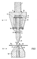
- FIG. 1 of the accompanying drawings is a suitable bend Device for performing the method shown schematically in vertical section.
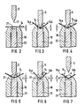
- 2-7 show schematic cross-sectional sketches through punch, sheet metal and die during different phases of the bending process according to the invention.
- the bending device basically consists of a vertically movable upper tool A and a fixed lower tool B.
- the upper tool A is provided with a carrier 1, which is arranged on the movable bar of a press brake in a known manner.
- a connecting member 2 is fastened to the beam 1 of the bar by a welded connection 3, the connecting member 2 having a slot-like recess which extends essentially over the entire width of the connecting member and into which a punch holder 4 projects.
- the punch holder 4 is provided with a bending punch 5 which is used directly for bending a workpiece, e.g. a piece of sheet metal 14 is used.
- the stamp 5 is fastened in the stamp holder 4 by means of an extension 6 which engages in a corresponding groove 7 in the stamp holder 4 and is held there with clamping members 8.
- a membrane holder 12 which is supported against a holding flange 15, serves to hold the membrane 11 in place.
- the channel-like depression is filled with liquid 13, for example filled with pressure oil, the arrangement being such that the liquid pressure can be increased and decreased by known means, for example by a corresponding pump, not shown in the drawing.
- the bending punch 5 has a working edge 17 where the two working surfaces 16 of the punch 5 collide at an angle that is smaller than the smallest angle that can be produced with this tool.
- the lower tool B has a die body 18 which is equipped with a longitudinal groove 19 on its surface facing the punch 5. This longitudinal groove determines the bending angle by the relative position of the two contact edges 20 delimiting the groove opening and by the depth of the groove base 21.
- the flat longitudinal groove 19 is arranged in the vertical longitudinal center plane of the die body 18 and is adjustable Floor 21 equipped.
- the groove base 21 is formed, for example, by pins 22 acting as supports, which are inserted in vertical openings of the die body 18 arranged next to one another and are guided displaceably in these openings.
- the upper end faces of the pins 22 form the groove bottom 21.
- the pin ends facing away from the groove base 21 rest in a known manner on a stop bar, not shown, which is adjustable on an inclined surface and thus enables the groove base 21 to be raised or lowered precisely.
- the piece of sheet metal 14 to be deformed rests on the die body 18.
- the groove base 21 is first brought into a position in which the base together with the support edges 20 determines an angle which is greater than the setpoint angle.
- the sheet metal piece 14 is pressed against the groove bottom 21 with the help of the working edge 17.
- This preload is released by relieving the sheet metal piece 14, the relieving being carried out by withdrawing the bending punch 5.
- the adjustable groove base 22 is in a first position, in which the surface 21 of the groove base 22 is at a distance a below the surface of the die body 18. This position a corresponds to a specific bending angle ⁇ , which is somewhat larger than the predetermined bending angle ⁇ to be actually achieved.
- the pre-bent sheet 14 is then relieved by, for example, pulling back the bending punch 5 somewhat.
- the bent sheet springs back somewhat, so that the angle ⁇ ′ enclosed by the two legs 14a and 14b is somewhat larger than the theoretical bending angle ⁇ .
- This springback can be observed in practically all types of sheet and the size of the springback depends on the material and quality of the sheet, its thickness, etc.
- the effective angle ⁇ ' is measured, which is present when the sheet 14 is relieved. This can be done with the angle measuring device mentioned at the beginning.
- the size of the angle is known and the difference ( ⁇ ′ - ⁇ ) is formed.
- the position b of the die base 22 is known, in which the sheet would be bent exactly at an angle ⁇ .
- the springback rate ( ⁇ ′ - ⁇ ) is known. From this, the definitive position (b + ⁇ b) of the die base 21 can be calculated, in which the sheet 14 will ultimately have exactly the desired bend.
- the die base 22 is shifted into a second position, in which the surface 21 is at a distance (b + ⁇ b) from the surface of the die body 18.
- the amount of (b + ⁇ b) is slightly larger than the amount of a, corresponding to a smaller, resulting bending angle.
- the punch 5 is again pushed against the die 18 until the leading edge of the sheet metal bend touches the surface 21 of the die bottom 22, and then stopped.
- This situation is shown in Fig. 6.
- the two legs 14a and 14b of the sheet 14 include an angle ⁇ ', which is slightly smaller than the desired bending angle ⁇ .
- the sheet 14 After the sheet 14 has been relieved, e.g. by retracting the punch 5 (FIG. 7), the sheet 14 springs back somewhat in order to finally have the desired bending angle ⁇ .
- the first bending takes place at an angle of approximately 91 °, that is to say an angle which is certainly somewhat larger than the ultimately desired angle.
- the two legs spring back somewhat so that they now enclose an angle of 93 °. The difference is therefore 2 °.
- the die base is adjusted so much that after the second bend a bending angle of 88 ° results with the sheet loaded. If the sheet is relieved after the second bending operation, the two legs spring back by 1 ° each, with the result that the bending angle is exactly the desired 90 °.
Landscapes
- Engineering & Computer Science (AREA)
- Mechanical Engineering (AREA)
- Bending Of Plates, Rods, And Pipes (AREA)
Abstract
Beim Verfahren zum Biegen eines Werkstückes nach einem gegebenen Biegewinkel wird das Werkstück zunächst nach einem etwas grösseren Winkel gebogen als der gegebene Endbiegewinkel, worauf durch eine Entlastung des Biegestempels (5) die Entspannung des vorgebogenen Werkstückes (14) erfolgt. Danach wird der Betrag der Rückfederung durch Messung des effektiven Biegewinkels nach der ersten Biegeoperation ermittelt. Nun wird der Matrizenboden (22) derart verstellt, dass bei der nachfolgenden, zweiten Biegeoperation ein Biegewinkel resultieren würde, der dem gegebenen Endbiegewinkel minus dem Betrag der Rückfederung entspricht. Nach der Entlastung des Werkstückes nach der zweiten Biegeoperation wird das Werkstück derart zurückfedern, dass es genau den erwünschten Endbiegewinkel besitzt. 
Description
Die Erfindung bezieht sich auf ein Verfahren zum Biegen eines Werkstückes nach einem gegebenen Sollwinkel. Das Verfahren wird mit Hilfe einer Biegeeinrichtung ausgeübt, die einen Biegestempel sowie eine Biegematrize aufweist, welche einen dem zu bildenden Winkel entsprechend verstellbaren Matrizenboden besitzt.The invention relates to a method for bending a workpiece according to a given desired angle. The method is carried out with the aid of a bending device which has a bending punch and a bending die which has a die base which is adjustable in accordance with the angle to be formed.
Beim Blechbiegen mit einem Biegestempel und einer Matrize bietet die exakte Einhaltung eines vorgegebenen Biegewinkels grosse Schwierigkeiten. Der Biegewinkel kann zwar durch die Bestimmung der Eindringtiefe des Biegestempels in die Matrize bei einer gegebenen Breite der Matrize theoretisch genau berechnet werden, wobei jedoch die theoretischen Werte praktisch nicht erreicht werden können, da der tatsächliche Biegewinkel, je nach Genauigkeit des Stempelvorschubs in die Matrize sowie Qualität und Stärke des zu biegenden Blechstückes, kleinere oder grössere Abweichungen vom Sollwert aufweist.When bending sheet metal with a punch and a die, exact compliance with a given bending angle is very difficult. The bending angle can be theoretically calculated precisely by determining the depth of penetration of the bending punch into the die for a given width of the die, but the theoretical values cannot be achieved practically, since the actual bending angle, depending on the accuracy of the punch feed into the die, and Quality and thickness of the sheet metal piece to be bent, minor or major deviations from the target value.
Eine gewisse Verbesserung bringt die Verwendung einer Biegeeinrichtung, bei welcher der Biegewinkel sehr einfach und exakt eingestellt und auch geändert werden kann. Solche Biegeeinrichtungen weisen zweckmässigerweise eine Biegematrize auf, die einen verstellbaren Matrizenboden besitzt. Der Biegewinkel kann ohne Auswechslung der Matrize durch die Einstellung bzw. Änderung der Höhenlage des Matrizenbodens exakt bestimmt und geändert werden. Die Biegematrize weist an ihrer, dem Biegestempel zugekehrten Seite eine längsverlaufende Nut auf, die durch die relative Lage der beiden, die Nutenöffnung begrenzenden festen Auflagekanten und des beweglichen Nutengrundes den momentanen Biegewinkel bestimmt. Doch auch in diesem Fall tritt bei entlastetem Werkstück ein Rückfedern auf, so dass der tatsächliche Biegewinkel nicht mit dem theoretischen, berechneten Wert übereinstimmt.The use of a bending device, in which the bending angle can be set and changed very easily and precisely, brings a certain improvement. Such bending devices expediently have a bending die which has an adjustable die bottom. The bending angle can be exactly determined and changed without changing the die by adjusting or changing the height of the die bottom. The bending die points to it, the bending punch facing side on a longitudinal groove, which determines the current bending angle by the relative position of the two fixed contact edges delimiting the groove opening and the movable groove base. In this case, too, a springback occurs when the workpiece is unloaded, so that the actual bending angle does not match the theoretical, calculated value.
Aus diesem Grunde ist es unerlässlich, in Versuchsreihen bei einer bestimmten Blechqualität und -stärke die Abweichungen des Biegewinkels vom Sollwert zu ermitteln und eine entsprechende Korrektur des Stempelvorschubs in die Matrize bzw. eine Korrektur der Höhenlage des verstellbaren Matrizenbodens durchzuführen, bevor die eigentliche Produktion der abgebogenen Bleche beginnen kann.For this reason, it is essential to determine the deviations of the bending angle from the target value in a series of tests with a certain sheet quality and thickness and to carry out a corresponding correction of the punch feed into the die or a correction of the height of the adjustable die base before the actual production of the bent sheet Sheet metal can begin.
Es ist die Aufgabe der vorliegenden Erfindung, hier eine Verbesserung zu schaffen und ein Verfahren zum Biegen von Werkstücken nach einem gegebenen Sollwinkel nach dem Oberbegriff des Patentanspruches 1 vorzuschlagen, welches die Notwendigkeit von zeit- und materialintensiven Versuchsreihen vor der Produktion vermeidet und mit welchem Werkstücke unabhängig von der Materialqualität und -stärke sehr präzise gebogen werden können.It is the object of the present invention to provide an improvement here and to propose a method for bending workpieces according to a given desired angle according to the preamble of claim 1, which avoids the need for time-consuming and material-intensive series of tests before production and with which workpieces are independent of the material quality and thickness can be bent very precisely.
Gemäss der Erfindung wird dies mit den im kennzeichnenden Teil des Patentanspruchs 1 angegebenen Merkmalen erreicht.According to the invention, this is achieved with the features specified in the characterizing part of patent claim 1.
Dazu ist eine Einrichtung erforderlich, mit welcher der Blechwinkel während des Biegevorganges kontinuierlich und sehr genau gemessen werden kann. Zu diesem Zwecke hat die Anmelderin bereits ein Winkelmessgerät vorgeschlagen, welches ein gegen das zu messende Werkstück an einer ersten Stelle anlegbares Auflageelement, sowie einen mit dem Auflageelement schwenkbar verbundenen, an einer von dar ersten Anlagestelle entfernt liegenden Stelle gegen das zu messende Blechstück anlegbaren Tastkopf aufweist. Die Verbindung der Berührungsstellen des Auflageelementes und des Tastkopfes mit dem Werkstück definieren die momentane Winkellage des Werkstückes. Zum Erfassen der Schwenkbewegung des Tastkopfes ist ein Winkelmessorgan vorhanden.This requires a device with which the sheet metal angle can be measured continuously and very precisely during the bending process. For this purpose, the applicant has already proposed an angle measuring device which has a support element that can be placed against the workpiece to be measured at a first point, and a pivoting head that can be pivotally connected to the support element and can be placed against the piece of sheet metal to be measured at a point away from the first contact point . The connection of the contact points of the support element and the probe with the workpiece define the current angular position of the workpiece. An angle measuring element is provided for detecting the pivoting movement of the probe.
Mit einem solchen Winkelmessgerät kann der tatsächliche Blechwinkel kontinuierlich und exakt bestimmt werden, so dass eine Abweichung vom Sollwert bei jeder Winkelstellung genau bestimmbar ist.With such an angle measuring device, the actual sheet metal angle can be determined continuously and precisely, so that a deviation from the target value can be precisely determined at each angular position.
Eine weitere Massnahme, die zur Verbesserung der Genauigkeit beim Biegevorgang beiträgt, besteht darin, dass eine Deformation der primär am Pressvorgang beteiligten Elemente der Biegemaschine verhindert bzw. kompensiert wird, um eine ungenaue Bearbeitung des Werkstückes zu vermeiden.Another measure that contributes to improving the accuracy during the bending process consists in preventing or compensating for deformation of the elements of the bending machine that are primarily involved in the pressing process in order to avoid inaccurate machining of the workpiece.
Zu diesem Zwecke hat die Anmelderin bereits vorgeschlagen, einen Biegestempel zu verwenden, dessen Stempelhalter auf einem Stützelement ruht, das in einem Halterungsteil vertikal ver schiebbar und auf einem Ölkissen aufliegend gelagert ist. Dabei ist es von Vorteil, wenn das Ölkissen mit einer Membrane abgedeckt ist, auf welcher dann das Stützelement aufliegt. Um bei verschieden langen Biegestempeln eine Überkompensation der Durchbiegung zu vermeiden, wurde bereits von der Anmelderin weiter vorgeschlagen, einen Biegestempel zu verwenden, bei welchem der Stützbalken entlang seiner Längenausdehnung mehrfach unterteilt ist, so dass unabhängig voneinander vertikal verschiebbar geführte Balkenteile vorhanden sind.For this purpose, the applicant has already proposed to use a bending stamp, the stamp holder rests on a support element which ver vertically in a holding part is slidable and supported on an oil cushion. It is advantageous if the oil cushion is covered with a membrane on which the support element then rests. In order to avoid overcompensation of the deflection in the case of bending dies of different lengths, the applicant has already further proposed to use a bending die in which the support beam is divided several times along its length, so that beam parts which are guided vertically displaceably are present independently of one another.
Bei einer bevorzugten Ausführung des vorgeschlagenen Verfahrens zum Biegen eines Werkstückes nach einem gegebenen Sollwinkel wird eine Biegeeinrichtung verwendet, die einen elastisch abgestützten Biegestempel sowie eine Biegematrize mit einem dem zu bildenden Winkel entsprechend verstellbaren Matrizenboden aufweist.In a preferred embodiment of the proposed method for bending a workpiece according to a given desired angle, a bending device is used which has an elastically supported bending punch and a bending die with a die base which can be adjusted according to the angle to be formed.
Die Entlastung des Werkstückes im zweiten Arbeitsgang kann dabei in vorteilhafter Weise durch eine Verminderung des Druckes in der elastischen Stütze des Stempels erfolgen. Die volle Belastung des Stempels im letzten Arbeitsgang erfolgt dagegen durch die Erhöhung des Flüssigkeitsdruckes in der elastischen Stütze. In dieser Weise wird ein einfaches, zuverlässiges und präzises Vorgehen ermöglicht, welches das genaue Einhalten eines vorgegebenen Blechwinkels erlaubt.The work piece can be relieved in the second operation in an advantageous manner by reducing the pressure in the elastic support of the punch. The full load of the ram in the last step, however, takes place by increasing the fluid pressure in the elastic support. In this way, a simple, reliable and precise procedure is made possible, which allows the exact maintenance of a given sheet angle.
In Fig. 1 der beiliegenden Zeichnungen ist eine geeignete Bie geeinrichtung zur Ausübung des Verfahrens im Vertikalschnitt schematisch dargestellt. Die Fig. 2-7 zeigen schematische Querschnitts-Skizzen durch Stempel, Blech und Matrize während verschiedenen Phasen des erfindungsgemässen Biegeverfahrens.1 of the accompanying drawings is a suitable bend Device for performing the method shown schematically in vertical section. 2-7 show schematic cross-sectional sketches through punch, sheet metal and die during different phases of the bending process according to the invention.
Die Biegeeinrichtung besteht grundsätzlich aus einem vertikal beweglichen Oberwerkzeug A sowie aus einem festen Unterwerkzeug B. Das Oberwerkzeug A ist mit einem Träger 1 versehen, welcher am beweglichen Holm einer Abkantpresse in bekannter Weise angeordnet ist. Am Träger 1 des Holmes ist ein Verbindungsorgan 2 durch eine Schweissverbindung 3 befestigt, wobei das Verbindungsorgan 2 eine schlitzartige, sich im wesentlichen über die ganze Breite des Verbindungsorganes erstreckende Ausnehmung besitzt, in welche ein Stempelhalter 4 hineinragt. Der Stempelhalter 4 ist mit einem Biegestempel 5 versehen, der unmittelbar zur Biegung eines Werkstückes, z.B. eines Blechstückes 14 dient. Die Befestigung des Stempels 5 im Stempelhalter 4 erfolgt durch einen Fortsatz 6, welcher in eine korrespondierenden Nut 7 des Stempelhalters 4 eingreift und dort mit Klemmorganen 8 festgehalten ist.The bending device basically consists of a vertically movable upper tool A and a fixed lower tool B. The upper tool A is provided with a carrier 1, which is arranged on the movable bar of a press brake in a known manner. A connecting member 2 is fastened to the beam 1 of the bar by a welded connection 3, the connecting member 2 having a slot-like recess which extends essentially over the entire width of the connecting member and into which a punch holder 4 projects. The punch holder 4 is provided with a
Wesentlich ist, dass sich im Verbindungsorgan 2 eine kanalartige Vertiefung 9 befindet, welche sich über einen Teil der Breite der Ausnehmung erstreckt und mittels einer Membrane 11 abgedeckt ist. Zum Festhalten der Membrane 11 dient ein Membranhalter 12, welcher sich gegen einen Halteflansch 15 abstützt. Die kanalartige Vertiefung ist mit Flüssigkeit 13, z.B. mit Drucköl gefüllt, wobei die Anordnung so getroffen ist, dass der Flüssigkeitsdruck durch bekannte Mittel, z.B. durch eine entsprechende, in der Zeichnung nicht dargestellte, Pumpe erhöht und herabgesetzt werden kann.It is essential that there is a channel-
Der Biegestempel 5 weist eine Arbeitskante 17 auf, wo die beiden Arbeitsflächen l6 des Stempels 5 zusammenstossen und zwar unter einem Winkel, der kleiner ist als der kleinste, mit diesem Werkzeug herzustellende Winkel.The
Es ist möglich zwischen dem Stempelhalter 4 und der Membrane 11 ein Zwischenstück einzusetzen, welches als Stützbalken wirkt und entlang seiner Längenausdehnung mehrfach unterteilt ist, so dass immer nur ein Teil des Balkens der Belastung ausgesetzt wird, welcher Teil der effektiven Länge des zur Verwendung kommenden Stempelhalters 4 entspricht. Es kann so eine Überkompensation der Durchbiegung auch dann nicht auftreten, wenn der Stempelhalter 4 verhältnismässig kurz ist.It is possible to insert an intermediate piece between the stamp holder 4 and the membrane 11, which acts as a support beam and is divided several times along its length, so that only part of the beam is exposed to the load, which part of the effective length of the stamp holder used 4 corresponds. Overcompensation of the deflection cannot occur in this way even if the punch holder 4 is relatively short.
Das Unterwerkzeug B weist einen Matrizenkörper 18 auf, der an seiner dem Stempel 5 zugekehrten Fläche mit einer Längsnut 19 ausgerüstet ist. Diese Längsnut bestimmt durch die relative Lage der beiden die Nutenöffnung begrenzenden Auflagekanten 20 und durch die Tiefe des Nutengrundes 21 den Biegewinkel.The lower tool B has a
Die flache Längsnut l9 ist in der vertikalen Längsmittelebene der Matrizenkörpers 18 angeordnet und mit einem verstellbaren Boden 21 ausgerüstet. Zu diesem Zwecke wird der Nutenboden 21 z.B. durch als Stützen wirkende Stifte 22 gebildet, welche in nebeneinander angeordneten vertikalen Öffnungen des Matrizenkörpers 18 eingesetzt und in diesen Öffnungen verschiebbar geführt sind. Die oberen Stirnflächen der Stifte 22 bilden dabei den Nutenboden 21.The flat longitudinal groove 19 is arranged in the vertical longitudinal center plane of the
Zur Verstellung des Nutenbodens 21 ruhen die, dem Nutenboden 21 abgekehrten Stiftenden in bekannter Weise auf einer nicht dargestellten Anschlagleiste, die auf einer schrägen Fläche verstellbar ist und so ein präzises Heben oder Senken des Nutenbodens 21 ermöglicht.To adjust the
Das zu verformende Blechstück 14 liegt, wie aus der Fig. 1 ersichtlich, auf dem Matrizenkörper 18 auf. Zur Durchführung der Biegeoperation wird zunächst der Nutenboden 21 in eine Lage gebracht, in welcher der Boden zusammen mit den Auflagekanten 20 einen Winkel bestimmt, welcher grösser ist als der Sollwinkel. Durch Senken des Biegestempels 5 wird mit Hilfe der Arbeitskante 17 das Blechstück 14 gegen den Nutenboden 21 gepresst. In dieser Lage steht das Blechstück unter einer gewissen Vorspannung, welche materialbedingt ist. Diese Vorspannung wird dadurch gelöst, indem das Blechstück 14 entlastet wird, wobei die Entlastung durch Zurückziehen des Biegestempels 5 erfolgt. In bevorzugter Weise ist es aber auch möglich, die Entlastung des Bleckstückes 14 durch die Verminderung des Flüssigkeitsdruckes in der kanalartigen Vertiefung 9 zu bewirken. Damit federt das soll darauf hingewiesen werden, dass die Darstellungen stark übertrieben gezeichnet sind, um die während des Biegevorganges auftretenden Verhältnisse deutlicher darstellen zu können.As can be seen from FIG. 1, the piece of
In der Ausgangslage gemäss Fig. 2 ist der Biegestempel 5 hochgefahren und ein zu biegendes Blechstück 14 liegt auf der Oberfläche der Matrize 18 auf. Der verstellbare Nutenboden 22 ist dabei in einer ersten Stellung, bei der sich die Oberfläche 21 des Nutenbodens 22 in einer Distanz a unterhalb der Oberfläche des Matrizenkörpers 18 befindet. Diese Position a entspricht einem bestimmten Biegewinkel α, der etwas grösser ist als der tatsächlich zu erreichende, vorgegebene Biegewinkel β.2, the
Nun wird der Biegestempel 5 gegen die Matrize 18 hin verschoben, trifft auf die Oberfläche des Bleches 14 und beginnt, dieses zu biegen. Die Vorschubbewegung des Stempels 5 wird solange fortgesetzt, bis die vorlaufende Kante des Blechbuges auf die Oberfläche des Matrizenbodens 22 auftrifft und dann gestoppt. Jetzt schliessen die beiden Schenkel 14a und 14b des Bleches 14 den errechneten Winkel α ein. Diese Situation ist in Fig. 3 dargestellt.Now the
Anschliessend wird das vorgebogene Blech 14 entlastet, indem zum Beispiel der Biegestempel 5 etwas zurückgezogen wird. Wie aus der Darstellung der Fig. 4 zu sehen ist, federt das gebogene Blech etwas zurück, so dass der von den beiden Schenkeln 14a und 14b eingeschlossene Winkel α′ etwas grösser ist als der theoretische Biegewinkelα. Diese Rückfederung ist bei praktisch allen Blecharten zu beobachten und die Grösse der Rückfederung hängt von dem Material und der Qualität des Bleches, von dessen Dicke etc. ab.The
Als nächstes wird der effektive Winkel α′ gemessen, der bei entlastetem Blech 14 vorhanden ist. Dies kann mit dem eingangs erwähnten Winkelmessgerät erfolgen. Die Grösse des Winkels ist bekannt, und es wird die Differenz (α′ -α) gebildet. Des weiteren ist die Stellung b des Matrizenbodens 22 bekannt, bei welcher das Blech exakt zu einem Winkel β gebogen würde. Schliesslich ist die Rückfederungsrate (α′ -α) bekannt. Daraus lässt sich die definitive Stellung (b + Δb) des Matrizenbodens 21 berechnen, bei der das Blech 14 schliesslich genau die gewünschte Biegung aufweisen wird.Next, the effective angle α 'is measured, which is present when the
Gemass Fig 5 wird der Matrizenboden 22 in eine zweite Stellung verschoben, in der die Oberfläche 21 einen Abstand (b + Δb) von der Oberfläche des Matrizenkörpers 18 aufweist. Der Betrag von (b +Δb) ist etwas grösser als der Betrag von a, entsprechend einem kleineren, resultierenden Biegewinkel. Dann wird der Biegestempel 5 erneut gegen die Matrize 18 hin verschoben, bis die vorlaufende Kante des Blechbuges die Oberfläche 21 des Matrizenbodens 22 berührt, und dann gestoppt. Diese Situation ist in Fig. 6 dargestellt. Hierbei schliessen die beiden Schenkel 14a und 14b des Bleches 14 einen Winkel β′ ein, der etwas kleiner ist als der gewünschte Biegewinkel β.5, the
Nach der Entlastung des Bleches 14 z.B. durch Rückzug des Biegestempels 5 (Fig. 7) federt das Blech 14 wiederum etwas zurück, um schliesslich exakt den gewünschten Biegewinkel β aufzuweisen.After the
In der Praxis unterscheiden sich die beiden Winkel alpha und β nur sehr wenig; als Anhaltspunkt kann folgendes Beispiel dienen:In practice, the two angles alpha and β differ very little; The following example can serve as a guide:
Wenn ein Blech mit einem Winkel von exakt 90° gebogen werden soll, erfolgt die erste Biegung auf einen Winkel von etwa 91°, also auf einen Winkel, der sicher etwas grösser ist als der schlussendlich erwünschte Winkel. Nach erfolgter Entlastung des zum ersten Mal gebogenen Bleches federn die beiden Schenkel etwas zurück, so dass sie nun einen Winkel von 93° einschliessen. Die Differenz beträgt somit 2°.If a sheet is to be bent at an angle of exactly 90 °, the first bending takes place at an angle of approximately 91 °, that is to say an angle which is certainly somewhat larger than the ultimately desired angle. After the sheet metal, which was bent for the first time, has been relieved, the two legs spring back somewhat so that they now enclose an angle of 93 °. The difference is therefore 2 °.
Es kann davon ausgegangen werden, dass die Rückfederung nach der anschliessenden, zweiten Biegeoperation um denselben Winkelbetrag erfolgen wird, da die Verhältnisse im wesentlichen gleich bleiben. Somit wird, nach der Entlastung des Bleches, der Matrizenboden um soviel verstellt, dass nach der zweiten Biegung ein Biegewinkel von 88° bei belastetem Blech resultiert. Wird das Blech nach der zweiten Biegeoperation entlastet, federn die beiden Schenkel wieder um je 1° zurück, mit dem Resultat, dass der Biegewinkel exakt die erwünschten 90° beträgt.It can be assumed that the springback will take place after the subsequent, second bending operation by the same angular amount, since the conditions remain essentially the same. After the sheet has been relieved, the die base is adjusted so much that after the second bend a bending angle of 88 ° results with the sheet loaded. If the sheet is relieved after the second bending operation, the two legs spring back by 1 ° each, with the result that the bending angle is exactly the desired 90 °.
Sämtliche Vorgänge können automatisch und vorprogrammiert durchgeführt werden, da die beschriebenen, bereits bestehenden Einrichtungen zu diesem Zwecke in jeder Beziehung geeignet sind.All processes can be carried out automatically and preprogrammed, since the already existing facilities described are suitable for this purpose in every respect.
Claims (3)
dadurch gekennzeichnet, dass
in einem ersten Arbeitsgang die Höheneinstellung des Matrizenbodens (21) entsprechend einem ersten Winkel erfolgt, welcher grösser als der gegebene Sollwinkel ist, worauf das Werkstück (14) durch Senken des Stempels (5) bis zum Boden (21) der Matrize (18) diesem ersten Winkel entsprechend gebogen wird;
in einem zweiten Arbeitsgang das gebogene Werkstück (14) entlastet wird, so dass eine Rückfederung desselben in eine entspannte Lage erfolgt;
in einem dritten Arbeitsgang der durch das zurückgefederte, entspannte Werkstück (14) gebildete Winkel gemessen, mit dem ersten Winkel verglichen und die Stellung des Matrizenbodens (21) auf einen Wert korrigiert wird, der dem gegebenen Sollwinkel abzüglich der Differenz zwischen dem am entspannten Werkstück gemessenen Winkel und dem ersten Winkel entspricht, und worauf
in einem vierten Arbeitsgang das vorgebogene Werkstück (14) mit dem wieder voll belasteten Stempel (5) gegen den Matrizenboden (21) gedrückt wird, welcher die korrigierte definitive Höhenstellung einnimmt.1. Method for bending a workpiece according to a given desired angle with the aid of a bending device which has a bending punch and a bending die with a die bottom which can be adjusted in accordance with the bending angle to be formed,
characterized in that
in a first operation, the height of the die base (21) is adjusted according to a first angle, which is greater than the given nominal angle, whereupon the workpiece (14) by lowering the punch (5) to the bottom (21) of the die (18) the first angle is bent accordingly;
in a second operation, the bent workpiece (14) is relieved, so that the same springs back into a relaxed position;
in a third operation, the angle formed by the spring-back, relaxed workpiece (14) is measured, compared with the first angle and the position of the die base (21) is corrected to a value that corresponds to the given target angle minus the difference between that measured on the relaxed workpiece Angle and the first angle, and what
in a fourth operation the pre-bent workpiece (14) is pressed against the die base (21) with the again fully loaded punch (5), which takes on the corrected definite height position.
dadurch gekennzeichnet, dass
die Entlastung des Werkstückes im zweiten Arbeitsgang durch eine Verminderung des Flüssigkeitsdruckes in der elastischen Stütze (13) des Stempels (5) erfolgt.2. The method as claimed in claim 1, in which the bending device has a bending stamp which is mounted elastically under liquid pressure,
characterized in that
the work piece is relieved in the second operation by reducing the fluid pressure in the elastic support (13) of the punch (5).
dadurch gekennzeichnet, dass
die volle Belastung des Stempels (5) im letzten Arbeitsgang durch die Erhöhung des Flüssigkeitsdruckes in der elastischen Stütze (13) des Stempels (5) erfolgt.3. The method according to claim 2,
characterized in that
the full load of the stamp (5) in the last step is carried out by increasing the fluid pressure in the elastic support (13) of the stamp (5).
Applications Claiming Priority (2)
| Application Number | Priority Date | Filing Date | Title |
|---|---|---|---|
| AT1046/88 | 1988-04-25 | ||
| AT0104688A AT390575B (en) | 1988-04-25 | 1988-04-25 | METHOD FOR BENDING A WORKPIECE |
Publications (2)
| Publication Number | Publication Date |
|---|---|
| EP0340167A2 true EP0340167A2 (en) | 1989-11-02 |
| EP0340167A3 EP0340167A3 (en) | 1990-10-24 |
Family
ID=3505415
Family Applications (1)
| Application Number | Title | Priority Date | Filing Date |
|---|---|---|---|
| EP19890810290 Withdrawn EP0340167A3 (en) | 1988-04-25 | 1989-04-18 | Method of bending work pieces |
Country Status (4)
| Country | Link |
|---|---|
| US (1) | US4966029A (en) |
| EP (1) | EP0340167A3 (en) |
| JP (1) | JP2694617B2 (en) |
| AT (1) | AT390575B (en) |
Cited By (1)
| Publication number | Priority date | Publication date | Assignee | Title |
|---|---|---|---|---|
| WO2013116888A1 (en) * | 2012-02-10 | 2013-08-15 | Trumpf Maschinen Austria Gmbh & Co. Kg. | Press table or press beam having adjustable beam element |
Families Citing this family (14)
| Publication number | Priority date | Publication date | Assignee | Title |
|---|---|---|---|---|
| JPH072088Y2 (en) * | 1988-11-15 | 1995-01-25 | 株式会社小松製作所 | Tool position controller for bending machine |
| US5365767A (en) * | 1992-03-23 | 1994-11-22 | Steelcase Inc. | Brake press arrangement |
| US5408858A (en) * | 1994-01-24 | 1995-04-25 | Amada Engineering & Service Co., Inc. | Bending machine utilizing controlled expandable pressure device to apply uniform pressure to work material |
| US5857366A (en) * | 1994-07-08 | 1999-01-12 | Amada Company, Ltd. | Method of bending workpiece to target bending angle accurately and press brake for use in the same method |
| DE19519108C2 (en) * | 1995-05-24 | 1999-03-25 | Knupfer Metallverarb Gmbh | Method and device for measuring angles, in particular bending angles of sheet metal parts |
| US6026573A (en) * | 1997-05-14 | 2000-02-22 | Dana Corporation | Method for manufacturing a side rail for a vehicle frame assembly |
| IT1311827B1 (en) * | 1999-04-16 | 2002-03-19 | Luciano Gasparini | SELF-CENTERING TILTING FORK OF THE FORK, PARTICULARLY FOR MEASURING ON FOUR POINTS OF THE |
| EP1539394B1 (en) * | 2002-05-08 | 2013-03-06 | Avure Technologies AB | Device and method for expansion forming |
| US20070056348A1 (en) * | 2005-09-09 | 2007-03-15 | David Leland | Brake punch inserts |
| CN103406403B (en) * | 2013-08-01 | 2015-05-13 | 江苏鹏诚钢构有限公司 | Pressure flat bending device |
| CN104056881B (en) * | 2013-10-17 | 2016-02-17 | 攀钢集团攀枝花钢铁研究院有限公司 | Sheet metal bending apparatus |
| JP6846267B2 (en) * | 2017-04-04 | 2021-03-24 | 株式会社アマダ | Bending method of lower mold device and workpiece |
| EP3991869B1 (en) * | 2019-06-28 | 2025-11-12 | Kawasaki Jukogyo Kabushiki Kaisha | Press brake, and method for operating press brake |
| CN117548532B (en) * | 2024-01-11 | 2024-04-05 | 沈阳华铁异型材有限公司 | Iron ladle strip bending device and bending method thereof |
Family Cites Families (19)
| Publication number | Priority date | Publication date | Assignee | Title |
|---|---|---|---|---|
| US3552182A (en) * | 1968-11-20 | 1971-01-05 | Wisconsin Machine Corp | Press brake with hydraulic ram adjustment |
| US3760622A (en) * | 1972-02-01 | 1973-09-25 | I Mansell | Elastomeric forming die |
| AT311153B (en) * | 1972-04-13 | 1973-11-12 | Haemmerle Ag Maschf | Sheet metal working equipment |
| AT311152B (en) * | 1972-04-13 | 1973-11-12 | Haemmerle Ag Maschf | Bending tool |
| JPS5311273B2 (en) * | 1973-12-27 | 1978-04-20 | ||
| US3978706A (en) * | 1974-12-24 | 1976-09-07 | Nippon Kokan Kabushiki Kaisha | Precision bending work method for metallic materials |
| NL179349C (en) * | 1975-06-24 | Haemmerle Ag Maschf | BENDING TOOL. | |
| IT1072273B (en) * | 1977-02-01 | 1985-04-10 | Selecontrol Sas | DEVICE FOR THE DETECTION AND ADJUSTMENT OF BENDING ANGLES PARTICULARLY SUITABLE FOR PRESSES-FOLDERS |
| JPS54417A (en) * | 1977-06-03 | 1979-01-05 | Hayashigumi Kk | Method of construction of pressing in presssin pipe |
| DE2952108C2 (en) * | 1979-12-22 | 1983-11-24 | Hämmerle AG, Zofingen | Arrangement for height adjustment of the die base of bending tools for bending sheet metal |
| JPS57202928A (en) * | 1981-06-08 | 1982-12-13 | Amada Co Ltd | Bender |
| CH655874A5 (en) * | 1982-06-07 | 1986-05-30 | Haemmerle Ag Maschf | TOOL DEVICE ON A BENDING PRESS. |
| JPS5992120A (en) * | 1982-11-15 | 1984-05-28 | Hitachi Ltd | Bending device |
| EP0166351A3 (en) * | 1984-06-27 | 1986-09-17 | Arnold Stucki | Device at a machine for deformation work of sheet metals |
| AT381251B (en) * | 1984-10-18 | 1986-09-25 | Haemmerle Ag | METHOD FOR CORRECTING THE BENDING ANGLE WHEN BENDING WITH A BENDING STAMP |
| JPS61129522A (en) * | 1984-11-29 | 1986-06-17 | Hitachi Ltd | Bending angle detection/correction/processing method |
| JPS61229421A (en) * | 1985-04-03 | 1986-10-13 | Mitsubishi Heavy Ind Ltd | Bending method for plate like body |
| US4802357A (en) * | 1987-05-28 | 1989-02-07 | The Boeing Company | Apparatus and method of compensating for springback in a workpiece |
| US4864509A (en) * | 1987-09-29 | 1989-09-05 | The Boeing Company | Method and related apparatus for controlling the operation of a press brake |
-
1988
- 1988-04-25 AT AT0104688A patent/AT390575B/en active
-
1989
- 1989-04-14 US US07/339,074 patent/US4966029A/en not_active Expired - Lifetime
- 1989-04-18 EP EP19890810290 patent/EP0340167A3/en not_active Withdrawn
- 1989-04-24 JP JP1104365A patent/JP2694617B2/en not_active Expired - Lifetime
Cited By (4)
| Publication number | Priority date | Publication date | Assignee | Title |
|---|---|---|---|---|
| WO2013116888A1 (en) * | 2012-02-10 | 2013-08-15 | Trumpf Maschinen Austria Gmbh & Co. Kg. | Press table or press beam having adjustable beam element |
| CN104203445A (en) * | 2012-02-10 | 2014-12-10 | 特鲁普机械奥地利有限公司及两合公司 | Press table or press beam having adjustable beam element |
| US9381558B2 (en) | 2012-02-10 | 2016-07-05 | Trumpf Maschinen Austria Gmbh & Co. Kg. | Press table or press beam having adjustable beam element |
| CN104203445B (en) * | 2012-02-10 | 2016-11-23 | 特鲁普机械奥地利有限公司及两合公司 | Squeeze station or pressing beam including adjustable beam element |
Also Published As
| Publication number | Publication date |
|---|---|
| AT390575B (en) | 1990-05-25 |
| ATA104688A (en) | 1989-11-15 |
| JP2694617B2 (en) | 1997-12-24 |
| US4966029A (en) | 1990-10-30 |
| EP0340167A3 (en) | 1990-10-24 |
| JPH01313112A (en) | 1989-12-18 |
Similar Documents
| Publication | Publication Date | Title |
|---|---|---|
| DE69710101T2 (en) | BENDING PRESS | |
| EP0340167A2 (en) | Method of bending work pieces | |
| DE2630896C3 (en) | Device for bending large components | |
| EP0341211B1 (en) | Method of bending sheet metal | |
| DE29623800U1 (en) | Processing machine for folding workpieces | |
| EP1961502A2 (en) | Method and device for bending workpieces | |
| AT518993B1 (en) | Method for operating a bending machine | |
| DE102012013371B4 (en) | Measuring device for a ram cushion of a press | |
| DE3120093A1 (en) | RIVETING MACHINE, IN PARTICULAR FOR RIVETING THE BRAKE PADS ON THE PAD BRAKE PAD | |
| EP0096278A2 (en) | Method of binding plate, and apparatus for doing so | |
| EP1793946A1 (en) | Method for producing a workpiece by forming under bending conditions | |
| EP2548668B1 (en) | Method for automatically torsion straightening of longitudinal workpieces | |
| EP3155366B1 (en) | Calibration tool for an angle measuring tool in a bending die and method for calibrating the angle measuring tool | |
| AT512465B1 (en) | PRESSTISCH OR PRESSBALKEN WITH ADJUSTABLE BEAM ELEMENT | |
| AT511711B1 (en) | MANUFACTURING DEVICE WITH BENDING TOOLS AND POSITIONING EQUIPMENT | |
| EP3953164A1 (en) | Method and measuring device for measuring or calibrating utensils in pressing processes | |
| AT381251B (en) | METHOD FOR CORRECTING THE BENDING ANGLE WHEN BENDING WITH A BENDING STAMP | |
| DE1292112B (en) | Device for punching rivet nuts in sheet metal workpieces | |
| CH695668A5 (en) | Measurement and control device in a Abkantfpresse. | |
| DE3245753A1 (en) | Method for setting a dimensionally accurate penetration path of the top tool of a bending press, in particular a folding press | |
| DE2805206C2 (en) | Bending tool for manufacturing U-shaped workpieces | |
| EP0492193A1 (en) | Method and device for inserting a pin in a thin plate | |
| DE1502706B2 (en) | SHEET METAL PROCESSING MACHINE, IN PARTICULAR TABLE SHEARS | |
| EP0128342B1 (en) | Press having a part-ejection device and a closing-height adjusting device | |
| DE1193337B (en) | Machine tool with a support arm that can be pushed out of a recess in its stand |
Legal Events
| Date | Code | Title | Description |
|---|---|---|---|
| PUAI | Public reference made under article 153(3) epc to a published international application that has entered the european phase |
Free format text: ORIGINAL CODE: 0009012 |
|
| AK | Designated contracting states |
Kind code of ref document: A2 Designated state(s): BE CH DE ES FR GB IT LI LU NL SE |
|
| PUAL | Search report despatched |
Free format text: ORIGINAL CODE: 0009013 |
|
| AK | Designated contracting states |
Kind code of ref document: A3 Designated state(s): BE CH DE ES FR GB IT LI LU NL SE |
|
| 17P | Request for examination filed |
Effective date: 19901122 |
|
| 17Q | First examination report despatched |
Effective date: 19920731 |
|
| STAA | Information on the status of an ep patent application or granted ep patent |
Free format text: STATUS: THE APPLICATION IS DEEMED TO BE WITHDRAWN |
|
| 18D | Application deemed to be withdrawn |
Effective date: 19921211 |