EP0340076B1 - Vorrichtung zum Halten und Laden von länglichen Gegenständen, insbesondere Leitern auf dem Dach eines Fahrzeuges - Google Patents
Vorrichtung zum Halten und Laden von länglichen Gegenständen, insbesondere Leitern auf dem Dach eines Fahrzeuges Download PDFInfo
- Publication number
- EP0340076B1 EP0340076B1 EP19890401070 EP89401070A EP0340076B1 EP 0340076 B1 EP0340076 B1 EP 0340076B1 EP 19890401070 EP19890401070 EP 19890401070 EP 89401070 A EP89401070 A EP 89401070A EP 0340076 B1 EP0340076 B1 EP 0340076B1
- Authority
- EP
- European Patent Office
- Prior art keywords
- slides
- carriages
- vehicle
- slide rails
- straps
- Prior art date
- Legal status (The legal status is an assumption and is not a legal conclusion. Google has not performed a legal analysis and makes no representation as to the accuracy of the status listed.)
- Expired - Lifetime
Links
- 238000005096 rolling process Methods 0.000 claims description 5
- 230000005484 gravity Effects 0.000 claims description 4
- 230000000284 resting effect Effects 0.000 claims description 4
- 238000004804 winding Methods 0.000 claims description 4
- 230000001360 synchronised effect Effects 0.000 claims description 2
- 230000002829 reductive effect Effects 0.000 description 3
- 125000006850 spacer group Chemical group 0.000 description 3
- 210000003323 beak Anatomy 0.000 description 2
- 230000000903 blocking effect Effects 0.000 description 2
- 230000036961 partial effect Effects 0.000 description 2
- 238000009434 installation Methods 0.000 description 1
- 238000002955 isolation Methods 0.000 description 1
- 230000000670 limiting effect Effects 0.000 description 1
- 238000012423 maintenance Methods 0.000 description 1
- 238000004519 manufacturing process Methods 0.000 description 1
- 239000006223 plastic coating Substances 0.000 description 1
- 108090000623 proteins and genes Proteins 0.000 description 1
- 230000000717 retained effect Effects 0.000 description 1
Images


Classifications
-
- B—PERFORMING OPERATIONS; TRANSPORTING
- B60—VEHICLES IN GENERAL
- B60R—VEHICLES, VEHICLE FITTINGS, OR VEHICLE PARTS, NOT OTHERWISE PROVIDED FOR
- B60R9/00—Supplementary fittings on vehicle exterior for carrying loads, e.g. luggage, sports gear or the like
- B60R9/04—Carriers associated with vehicle roof
- B60R9/042—Carriers characterised by means to facilitate loading or unloading of the load, e.g. rollers, tracks, or the like
- B60R9/0423—Carriers characterised by means to facilitate loading or unloading of the load, e.g. rollers, tracks, or the like for ladders
Definitions
- the present invention relates to an apparatus for handling and loading elongated objects on the roof of a motor vehicle, more particularly of the van or van type.
- French patent FR-A-2,556,706 to the applicant describes an apparatus of this type, comprising slides adapted to be fixed to the front and rear ends of the roof and extending transversely to the level of at least one of the two side walls of the vehicle.
- Flexible links constituted for example by straps, bear on the slides, and can be wound around an axis fixed longitudinally to the roof, by means of driving this axis in rotation (winch maneuvered by a manual rod located at the rear of the vehicle).
- Arms constituting the supports of elongated objects, in particular ladders, are fixed to the ends of flexible links, the ends of which are connected by a rigid spacer.
- the object of the invention is to provide an apparatus for handling and loading elongated objects, which does not have these drawbacks.
- the slides extend transversely to the level of at least one of the side walls of the vehicle, the end portions of the slides opposite the axis of rotation are provided with hooks having beaks bent upwards.
- a rigid longitudinal bar connects the ends of the drawers located on the side of the axis of rotation, and the ends of this bar can engage in the hooking spouts of the bar, in order to retain the drawers and the hanging carriages. along the side wall of the vehicle in the low standby position.
- the lateral dimensions of the device are reduced because the slides do not extend along the walls of the vehicle, and the hooks make it possible to retain the drawers and the carriages in the low waiting position.
- two flexible links are associated with each slide, namely a first flexible link of which one end is attached to the corresponding carriage and a second shorter flexible link of which one end is attached to the link bar, and these two links are wound on respective drums, the diameters of which are chosen so as to provide the two links with synchronized winding and unwinding speeds.
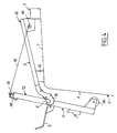
- Figure 1 is a perspective view of an embodiment of a handling and loading device according to the invention, mounted on the roof of a van type vehicle, and whose drawers and carriages are in position low waiting.
- FIG. 2 is an elevational view with partial cutaway of the apparatus of FIG. 1, taken between two slides.
- FIG. 2A is a partial elevation view on an enlarged scale of a detail of FIG. 2.
- FIG. 3 is a view similar to FIG. 2 showing the carriage in the raised position on its support drawer, the latter still being in the low standby position.
- Figure 4 is an elevational view of the apparatus at the start of the tilting of the drawers and carriages on the hooks of the slides.
- Figure 5 is a mid-longitudinal sectional mid-elevation view of a slide and the drawer as well as the associated carriage, shown during installation on the slide.
- FIG. 6 is a view similar to FIG. 5 showing the drawer and its carriage in the loading position, locked on the slide.
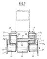
- Figure 7 is a mid-sectional mid-elevation view, on an enlarged scale, of a carriage and its drawer bearing on the associated slide.
- Figure 8 is an elevational view of an automatic locking device of the rotary axis drive winch when the drawers are raised on the slides.
- FIG. 9 is a view similar to FIG. 8 showing the device unlocked by introducing the hook of a winch operating rod.
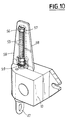
- Figure 10 is an elevational view of another embodiment of the automatic winch locking device.
- FIG. 11 is a view similar to FIG. 4 of a second embodiment of the handling device according to the invention.
- FIG. 12 is a perspective view similar to FIG. 1 of the embodiment of FIG. 11.
- the apparatus shown in the drawings is intended for handling and loading elongated objects, such as ladders, on the roof 1 of a vehicle 2, the latter being of the van or pickup type.
- This device comprises, in the example described, two slides 3 adapted to be fixed to the front and rear ends of the roof 1 and extending transversely to the level of one 4 of the two side walls of the vehicle 2.
- the device also comprises several flexible links formed here, for each slide 3, by two straps 5 and 40.
- the straps 5 bear on the slides 3 and can be wound around an axis 6 mounted longitudinally on two fixed parts 7 secured to the roof 1.
- the arrangement of the straps 40 as well as their role and that of the straps 5 will be explained below.
- the axis 6 can be rotated from the rear of the vehicle by any suitable device such as a winch 10 and a rod 8 manual or electric maneuver.
- the objects (not shown) are arranged on supports 9 fixed to the ends of the flexible links 5 and constituted in a manner known per se by arms extending transversely and the end of which is raised.
- the supports 9 are pivotable on vertical axes integral with carriages 11 slidably mounted on rigid drawers 12 which can themselves slide on the corresponding slides 3 to be locked thereon (Fig.5).
- a rigid longitudinal bar 13 connects the ends of the two drawers 12 located on the side of the axis 6, and the end portions of the slides 5 opposite the axis of rotation 6 are provided with means for hooking the bar 13 in order to retain the drawers 12 and the carriages 11 suspended along the side wall 4 in the low waiting position.
- these hooking means are hooks 14 having beaks 14a bent upwards, each slide 3 thus being provided with two end hooks 14 separated by a passage interval between the drawers 12 and the corresponding carriages 11. In these intervals engage the ends of the bar 13 when the drawers 12 and the carriages 11 are suspended along the side wall 4 (Fig.1 and 3), which can be protected by a plastic coating or the like.
- Each strap 40 can be wound around a drum 43 secured to the rotary axis 6. It also slides on a return roller 45 carried by a hook 14 and its end is attached to the bar 13, in the vicinity of the hooks 14. It is therefore shorter than the strap 5 associated with the same slide 3, and which is wound on a drum 44, the diameter of which is clearly greater than that of the drum 43. In fact the ratio of these two diameters must be suitably chosen to ensure synchronization of the windings and unwinds of the four straps 5,40, the straps 5 having to unwind faster than the straps 40 due to their greater length.
- the straps 40 have the function essentially of facilitating the ascent on the slides 3 of the load (11,12) with the objects placed on the supports 9, and more precisely its tilting on the hooks 14 (Fig. 4) with an effort on the rod 8 significantly reduced compared to that which would be necessary in the absence of the straps 40.
- the slides 3 are supported, in the vicinity of the wall 4, on parts 16 fixed to the roof 1, and each comprise a profile 17, one end of which is secured to the corresponding hooks 14, while the other end is fixed to the part 7.
- This profile 17 has a U-shaped section inside which, in the vicinity of its end contiguous to the axis 6, is mounted a roller 18, while a second roller 19 is mounted between the hooks 14.
- a third roller 19a is mounted between the hooks 14.
- Each carriage 12 has in cross section a profile in two C 21 open towards one another (Fig. 6), joined by a bottom 22 pierced with an elongated opening 23 for passage of the associated strap 5 (Fig. 5 ).
- the latter also passes through a lumen 24 from the bottom of the carriage 11, while its end is attached in a manner known per se to the support 9.
- the profiles in C 21 are spaced from each other by a sufficient interval to allow with play, to receive the carriage 11, which for this purpose may have a U-shaped section at the bottom 24 whose branches are extended at right angles by flaps 25 which can slide on the underlying ends 21a of the C profiles 21.
- the device comprises rolling means for the carriages 11 on the drawers 12 as well as drawers 12 on the slides 3, and stops 20, fixed to the drawers 12, for stopping the carriages 11 in the low position relative to the drawers 12 (Fig. .2).
- the rollers 18, 19 and 19a allow the rolling of the drawers 12 on the slides 3, the straps 5 bearing on these rollers when the drawers 12 and their carriages 11 are in the low position.
- the above rolling means also comprise a pair of rollers 26 mounted on an axis 27 passing through the upper end of the carriage 11, these rollers 26 resting on the branches 21b of the sections 21 opposite their branches 21a (Fig.7 ). Rollers 33 placed at the end of each slide 3 opposite the rollers 26 allow, with the latter, the carriages 11 to slide on the drawers 12.
- the ends of the drawers 12 located on the side of the axis 6 are equipped with means for securing the drawers with the corresponding carriage 11 before each maneuver for raising the drawer 12 and the carriage 11 on the roof 1, and for detaching them when they are folded down along the side wall 4.
- these means are locking latches 28 articulated on the ends of the connecting bar 13, and which come by gravity to hang on associated members integral with the upper ends drawers 12, for example transverse bars 29 receiving the curved ends 28a of the latches 28.
- the ends of the curved spouts 14a of the hooks 14 are arranged to cause the latches 28 to be raised when the bar 13 descends inside the hooks 14 ( Fig. 2), and therefore the automatic unlocking of the carriages 11 with respect to the drawers 12 during a maneuver of descent thereof along the wall 4 of the vehicle.
- the interior of the hooks 14 has in section the profile visible in particular in FIG. 2A: first of all external ramps 41 of access in V which allow the introduction of a straight profile 13a with two parallel dishes 13b forming each end of the connecting bar 13, then a bottom groove 42 in U with opposite parallel walls 42a.
- the end profiles 13a of the bar 13 are dimensioned so as to come to engage practically without play in the bottom of the groove 42.
- the ends of the drawers 12 located on the side of the axis of rotation 6 are provided with locking pieces 31 of all the drawers 12 and the carriages 11 on the slides 3 in the loaded position (Fig. 5). These end pieces 31 can be bent as shown, so that at the end of the sliding of the drawers 12 on the slides 3, their ends engage under bars 32 fixed transversely to the upper ends of the slides 3.
- Each drawer 12 is provided with a stopper 34 arranged to abut against the roller 19 of the slide 3, when the drawers 12 and the carriages 11 are in the high locked position on the roof 1 (FIG. 6).
- the carriages 11 are provided in a manner known per se with fasteners 35 intended to retain the objects attached to the supports 9, and the drawers 12 are equipped, at their lower ends, with rollers 36 bearing on the wall 4 of the vehicle.
- the ends of the axis 6 are provided with cam drums 30 (Fig. 6) adapted to block safety hooks 38 articulated inside the upper ends of the slides 3.
- the hooks 38 are arranged so as to tilt under the thrust of the drawers 12 and to block the latter at the end of the race, coming to engage under the rollers 26.
- the hooks 38 are held in this locking position by the cams 37 themselves held by the straps 5 and the weight of carriages 11 and their loads.
- the apparatus is finally provided with a device for automatically locking the drive means of the axis 6 in rotation, that is to say the winch 10 when the drawers 12 are raised on the slides 3 and at the end of race on these.
- this device thus comprises a member 46 for stopping the winch 10, formed by a butterfly mounted rocking on an axis 50 carried by a rotary ring 47 of the winch adapted to receive the end hook 48 of the rod 8.
- the housing fixed of the winch 10 is provided with a finger 49, and in the absence of the hook 48, the member 46 is resiliently recalled by a spring 51 wound around the axis 50 in a raised position against the winch housing 10, where its end can come into contact with the finger 49 which then constitutes a stop preventing any rotation of the ring 47 secured to the butterfly 46.
- the assembly operation of the assembly can begin, by rotation of the axis 6 by means of the winch 10 and the rod 8 and release of the stop member 46.
- the straps 5 quickly drive up the carriages 11 whose rollers 26 roll on the branches 21b of the profiles 21. At the end of the sliding of the carriages 11, these come into abutment against the bar 13 between the hooks 14 then the straps 5 continuing to wind around the axis 6, the drawers 12 are lifted from the hooks 14 with the carriages 11, which causes the latches 28 to be folded down on the axes 29 and the carriages 11 to be locked on the drawers 12 (FIG. 3). Up to this point, the straps 40 have been wound up empty on the axis 6 thanks to several dead turns, exerting no traction on the bar 13.
- the straps 40 which wind up a lot slower than the straps 5, pull on the bar 13 and start to take off the rollers 36 from the wall 4. They transmit the ascent force of the assembly and thanks to the lever arms between the latter and the axis of tilting at the level of the hooks 14 (FIG. 4), allow this tilting of the drawers 12 on the slides 3 with a reduced force on the crank 8.
- the drawers 12 roll successively on the rollers 19a then on the rollers 19 and the rollers 18 (Fig.5), continuing to slide on the slides 3.
- the hooks 38 are tilted and come block the rollers 26, while the cams 37 hold the hooks 38 in this blocking position.
- the traction exerted on the straps 5 by the carriages 11 and their loading tends to keep the cams 37 in their position for blocking the hooks 38.
- the parts 31 are placed under the bars 32, which guarantees the maintenance on the slides 3 of the drawers 12 of the carriages 11 and of their loading.
- the withdrawal of the crank 8 causes the winch 10 to be locked by the stop member 46.
- the apparatus according to the invention has in particular the advantage of not hindering access into the vehicle by a possible side door, thanks to the fact that the bar 13 connects the upper ends of the drawers 12, and is therefore always located at- above this side door.
- the drawers 12 and the carriages 11 always remain substantially parallel to the wall 11 if the vehicle is parked on a slope.
- FIG. 10 shows another embodiment of the automatic locking device of the winch 10.
- This device comprises a threaded rod 55 extending the axis of the winch 10 driven by its ring 47 and integral in rotation with this axis.
- the rod 55 carries a nut 56 blocked in rotation by any suitable means, for example by a sheath 57 partially or completely enveloping the nut 56 and whose cross section corresponds to that of this nut.
- the sheath 57, supported by the winch 10 is subject thereto by lateral cheeks 58.
- On the base of the rod 55 is screwed a fixed nut 59.
- the mobile nut 56 When the ladder supports 9 are in the low position, the mobile nut 56 is in the high position and in abutment against the upper end of the sheath 57, the position in which it is locked, as is the winch 10.
- This locking device therefore ensures the security against untimely unwinding of the straps.
- each pair of links 5, 40 is replaced by a single flexible link 61 subdivided, at an appropriate location, into two strands 61a and 61b.
- the first strand 61a has its end fixed to the corresponding carriage 12 in the same manner as in the previous embodiment, while the second strand 61b, shorter than the first, has its end fixed to the rigid connecting bar 13. Under these conditions the winding drums 43 of the previous embodiment are here eliminated, which simplifies the equipment and reduces the manufacturing cost.
- junction point 62 of the strands 61a and 61b must of course be suitably chosen so that the carriage 12 begins to tilt before its point of equilibrium is reached on the associated roller 19a, which must also be suitably positioned for this purpose.
- the apparatus of FIGS. 11 and 12 is equipped with small straps 63, preferably elastic, at the rate of one per slide 3.
- Each small strap or strap 63 is therefore fixed on the one hand to the slide corresponding 3, preferably in its middle zone, and on the other hand to the rigid bar 13.
- the elastic straps 63 force the bar 13 and the ends of the carriages 12 to engage in the spouts 14a hooks 14 for hooking, at the end of the descent of the supports 9.
- the straps 63 avoid therefore any risk that the carriages 12 and the bar 13 do not jump outside of the hooks 14 if the vehicle is on a slope and in the event of too rapid a descent, which further improves the safety of use of the device.
Landscapes
- Engineering & Computer Science (AREA)
- Mechanical Engineering (AREA)
- Fittings On The Vehicle Exterior For Carrying Loads, And Devices For Holding Or Mounting Articles (AREA)
- Handcart (AREA)
Claims (16)
- Vorrichtung zum Halten und Laden von länglichen Gegenständen auf dem Dach (1) eines Fahrzeugs, mit Gleitschienen (3), die am vorderen und hinteren Ende des Daches befestigt werden können, biegsamen Bändern (5), die gegen die Gleitschienen (3) anliegen und auf eine Achse (6) aufgerollt werden können, die in Längsrichtung auf dem Dach montiert ist, mit Antriebseinrichtungen (10,8), die diese Achse in Drehrichtung antreiben, und mit Stützen (9) für Gegenstände, die an den Enden der biegsamen Bänder angebracht sind und fest mit Schlitten (11) verbunden sind, die verschiebbar auf starren Stangen (12) angeordnet sind, die ihrerseits auf den Gleitschienen (3) verschiebbar sind, dadurch gekennzeichnet, daßa) die Gleitschienen (3) sich in Querrichtung bis zur Höhe wenigstens einer der seitlichen Wände (4) des Fahrzeugs erstrecken,b) die Endstücke des Gleitschienen (3), die der Drehachse gegenüberliegen, mit Haken (14) versehend sind, die nach oben gekrümmte Mundstücke (14a) aufweisen,c) eine starre, längsgerichtete Stange (13) die Enden der Stangen (12) auf der Seite der Drehachse (6) verbindet, und daß die Enden dieser Stange (13) in die Mundstücke (14a) zum Aufhängen der Stange eingreifen und damit die Stangen (12) und die Schlitten, die an der Seitenwand (4) des Fahrzeugs in einer niedrigen Bereitschaftsstellung aufgehängt sind, halten.
- Vorrichtung nach Anspruch 1, dadurch gekennzeichnet, daß die beiden biegsamen Bänder (5,40) jeder Gleitstange (3) zugeordnet sind, daß ein erstes flexibles Band (5) vorgesehen ist, dessen eines Ende an dem entsprechenden Schlitten (11) angebracht ist, und ein zweites biegsames Band (40), das kürzer ist und dessen eines Ende an der Verbindungsstange (13) befestigt ist, und daß die beiden biegsamen Bänder (5,40) auf Trommeln (44,43) aufgerollt werden, deren Durchmesser derart gewählt sind, daß die Aufrollgeschwindigkeit und Abrollgeschwindigkeit der beiden Bänder synchronisiert ist.
- Vorrichtung nach einem der Ansprüche 1 und 2, dadurch gekennzeichnet, daß die Enden der Stangen (12) auf der Seite der Drehachse (6) mit Verbindungseinrichtungen zum Verbinden mit dem entsprechenden Schlitten (11) vor jedem Anheben der Stange und des Zugehörigen Schlittens auf dem Dach (1) des Fahrzeugs (2) versehen sind, die die Schlitten freigeben, wenn diese entlang den Seitenwänden (4) des Fahrzeugs heruntergeklappt sind.
- Vorrichtung nach Anspruch 3, dadurch gekennzeichnet, daß die Einrichtung Verriegelungs-Klinken (28) umfaßt, die an den Enden der Verbindungsstange (13) gelenkig gelagert sind und die durch Schwerkraft in die zugehörigen Organe (29) einhaken, die fest mit den Enden der Stangen verbunden sind, und daß die Enden (14a) der nach oben gekrümmten Haken (14) eine Anhebung der Klinken (28) hervorrufen, wenn die Stange (13) mit den Haken in Eingriff tritt, und damit eine automatische Entriegelung der Schlitten (11) in bezug auf die Stangen (12) währen des Herablassens der Stangen entlang der Wand des Fahrzeugs hervorrufen.
- Vorrichtung nach einem der Ansprüche 1 bis 4, dadurch gekennzeichnet, daß die Enden der Stangen (12) auf der Seite der Drehachse (6) mit Blockiergliedern (31) versehen sind, die die Anordnung aus Stangen (12) und Schlitten (11) auf den Gleitschienen in der beladenen Stellung blockieren, beispielsweise profilierte Bauteile, die mit Haltestäben (32) in Eingriff treten, die in Querrichtung auf den oberen Enden der Gleitschienen (3) befestigt sind.
- Vorrichtung nach einem der Ansprüche 1 bis 5, dadurch gekennzeichnet, daß die Stangen (12) Ausnehmungen (23) aufweisen, in denen die biegsamen Bänder (5) laufen können, an deren Enden die beweglichen Schlitten (11) angebracht sind, und daß die Stangen mit Rollen (36) versehen sind, die sich an den seitlichen Wänden (4) des Fahrzeugs (2) abstützen.
- Vorrichtung nach einem der Ansprüche 1 bis 6, dadurch gekennzeichnet, daß die Vorrichtung Einrichtungen zum Abrollen der Schlitten (11) auf den Stangen (12) und der Stange auf den Gleitschienen (13) umfaßt, die auf dem Dach befestigt sind, und daß die Stangen (12) mit Anschlägen (20) für die Schlitten (11) in der unteren Position versehen sind.
- Vorrichtung nach Anspruch 7, dadurch gekennzeichnet, daß diese Rolleinrichtungen Laufrollen (18,19,19a) aufweisen, die in den Gleitschienen (3) angeordnet sind und auf denen die entsprechenden Stangen (12) abrollen können und die gegen die biegsamen Bänder (5) anliegen, wenn die Stangen und ihre Schlitten (11) in der unteren Position sind.
- Vorrichtung nach einem der Ansprüche 1 bis 8, dadurch gekennzeichnet, daß die Enden der Drehachse (6) mit Nocken (37) versehen sind, die es gestatten, Sicherheitshaken (38) zu blockieren, die die Stangen (12) und die Schlitten (11) auf den Gleitschienen (3) halten.
- Vorrichtung nach einem der Ansprüche 7 bis 9, dadurch gekennzeichnet, daß die Stangen (12) profiliert sind und damit Laufrollen (26) aufnehmen, die an den oberen Enden der Schlitten (11) angebracht sind, sowie mit Laufrollen (33) für die Schlitten (11) versehen sind.
- Vorrichtung nach einem der Ansprüche 1 bis 10, dadurch gekennzeichnet, daß im Inneren der Haken (14) Einlaßrampen in V-Form vorgesehen sind, daß eine bodenseitige Nut (42) mit parallelen gegenüberliegenden Wänden (42a) folgt, und daß die Endprofile (13a) der Verbindungsstange (13) parallele gegenüberliegende Platten (13b) aufweisen, die so dimensioniert sind, daß sie praktisch spielfrei in den entsprechenden Nuten (42) der Haken (14) liegen können.
- Vorrichtung nach einem der Ansprüche 1 bis 11, dadurch gekennzeichnet, daß die Vorrichtung mit einer Einrichtung zum automatischen Verriegeln der Antriebseinrichtung der Drehachse (6) versehen ist, die in Funktion tritt, wenn die Stangen (12) in der angehobenen Position auf den Gleitschienen (3) liegen und die Bewegung auf diesen beendet ist oder in der unteren Bereitschaftsposition.
- Vorrichtung nach Anspruch 12, dadurch gekennzeichnet, daß die automatische Verriegelungseinrichtung ein Rastorgan (46) einer Hubeinrichtung (10) umfaßt, das pendelnd auf einem drehbaren Ring (47) der Hubeinrichtung angeordnet ist, der das Ende einer Rotations-Antriebsstange aufnimmt, welches Rastorgan elastisch in eine Position vorgespannt ist oder dessen Drehung durch einen Anschlag (49) blockiert ist, der am Gehäuse der Hubeinrichtung (10) angebracht ist, welches Rastorgan (46) von dem Anschlag (49) freikommt durch Einführen des Endes der Antriebsstange (8) in den Ring (47).
- Vorrichtung nach Anspruch 12, dadurch gekennzeichnet, daß die automatische Verriegelungseinrichtung eine Gewindespindel (55) umfaßt, die die Antriebsachse der Hubeinrichtung (10) verlängert und ein Ende (48) einer Rotations-Antriebsstange (8) aufnimmt, die drehfest mit diese Achse verbunden ist, welche Gewindespindel eine Mutter (56) aufnimmt, die in Drehrichtung durch ein Gehäuse (57) festgelegt ist, dessen Querschnitt demjenigen der Mutter entspricht, welche Mutter (56) in Längsrichtung der Gewindespindel (55) während der Betätigung der Hubeinrichtung derart beweglich ist, daß sie in der oberen Position liegt, wenn die Stützen (9) des Gegenstandes in der unteren Position liegen, und umgekehrt.
- Vorrichtung nach Anspruch 1, dadurch gekennzeichnet, daß nur ein biegsames Band (61) vorgesehen ist, das in zwei Zweige unterteilt ist, und das jeweils einer Gleitschiene (3) zugeordnet ist, und daß der erste Zweig (61a) mit seinem Ende an dem entsprechenden Schlitten (11) befestigt ist, und der zweite Zweig (61b), der kürzer ist, mit einem Ende an der starren Verbindungsstange (13) angebracht ist.
- Vorrichtung nach einem der Ansprüche 1 bis 15, dadurch gekennzeichnet, daß vorzugsweise elastische Gurtbänder (63) einerseits an den Gleitschienen (3) und andererseits an der starren Stange (13) angebracht sind, die die letzteren und die Stangen (12) in die Mitnahme-Mundstücke (14a) am Ende der Abstiegsbewegung der Stützen (9) einklinken.
Applications Claiming Priority (2)
| Application Number | Priority Date | Filing Date | Title |
|---|---|---|---|
| FR8805463 | 1988-04-25 | ||
| FR8805463A FR2630381B1 (fr) | 1988-04-25 | 1988-04-25 | Appareil de manutention et de chargement d'objets allonges tels que des echelles sur le toit d'un vehicule |
Publications (2)
| Publication Number | Publication Date |
|---|---|
| EP0340076A1 EP0340076A1 (de) | 1989-11-02 |
| EP0340076B1 true EP0340076B1 (de) | 1992-11-04 |
Family
ID=9365645
Family Applications (1)
| Application Number | Title | Priority Date | Filing Date |
|---|---|---|---|
| EP19890401070 Expired - Lifetime EP0340076B1 (de) | 1988-04-25 | 1989-04-18 | Vorrichtung zum Halten und Laden von länglichen Gegenständen, insbesondere Leitern auf dem Dach eines Fahrzeuges |
Country Status (4)
| Country | Link |
|---|---|
| EP (1) | EP0340076B1 (de) |
| DE (1) | DE68903356T2 (de) |
| ES (1) | ES2036041T3 (de) |
| FR (1) | FR2630381B1 (de) |
Families Citing this family (8)
| Publication number | Priority date | Publication date | Assignee | Title |
|---|---|---|---|---|
| FR2654688B1 (fr) * | 1989-11-17 | 1992-03-06 | Sibille & Cie Ateliers | Dispositif de chargement et de transport d'objets allonges tels que des echelles sur un toit de vehicule. |
| DE4338609A1 (de) * | 1993-11-11 | 1995-05-18 | Wilhelm Schwarz | Dachträgersystem für Kraftfahrzeuge mit Hochdach |
| EP1055560A1 (de) * | 1999-05-25 | 2000-11-29 | Tony Brändle AG Wil | Lade- und Abladevorrichtung für eine in Längsrichtung auf einem Fahrzeugdach liegend zu transportierende Last |
| US9327654B2 (en) * | 2007-11-05 | 2016-05-03 | Adrian Steel Company | Ladder rack system |
| US9694756B2 (en) | 2014-07-23 | 2017-07-04 | Knaack Llc | Drop down ladder rack |
| NO342801B1 (no) | 2017-04-26 | 2018-08-06 | Hpg As | Hev- og senkbar anordning, samt system for understøttelse av last |
| US11162261B2 (en) * | 2018-03-23 | 2021-11-02 | Harsoyo Lukito | Cross-struts for beam assemblies and ladder loader |
| US11590900B2 (en) * | 2019-08-22 | 2023-02-28 | Techno-Fab 9000 Inc. | Ladder rack for a vehicle |
Family Cites Families (9)
| Publication number | Priority date | Publication date | Assignee | Title |
|---|---|---|---|---|
| DE8327842U1 (de) * | 1984-04-19 | Gratza, Heidi, 8000 München | Dachständer für Kraftfahrzeuge | |
| DE7934167U1 (de) * | 1981-06-04 | Hartmann, Klaus, Dipl.-Ing., 8900 Augsburg | Dachlastträger für Personenkraftfahrzeuge | |
| DE7922468U1 (de) * | 1979-12-06 | Kleindienst Gmbh & Co Kg, 8900 Augsburg | Dachständer für Kraftfahrzeuge | |
| US4175905A (en) * | 1979-02-16 | 1979-11-27 | Garrison R Leonard Jr | Boat loader |
| GB2118501B (en) * | 1982-03-02 | 1984-12-05 | Ronic Staal Bv | Roof rack device |
| FR2587691B2 (fr) * | 1983-12-15 | 1988-07-08 | Sibille & Cie Ateliers | Appareil de manutention destine a hisser des charges sur le toit d'un vehicule |
| FR2556706B1 (fr) * | 1983-12-15 | 1987-03-20 | Sibille & Cie Ateliers | Appareil de manutention destine a hisser des charges sur le toit d'un vehicule |
| FR2600954B1 (fr) * | 1986-07-07 | 1990-01-12 | Sibille & Cie Ateliers | Appareil de manutention de charges allongees, telles que des echelles sur le toit d'un vehicule |
| FR2606344A1 (fr) * | 1986-11-12 | 1988-05-13 | Surirey Jagou Carrosserie | Dispositif porte-charges en particulier porte-echelle |
-
1988
- 1988-04-25 FR FR8805463A patent/FR2630381B1/fr not_active Expired - Fee Related
-
1989
- 1989-04-18 EP EP19890401070 patent/EP0340076B1/de not_active Expired - Lifetime
- 1989-04-18 ES ES89401070T patent/ES2036041T3/es not_active Expired - Lifetime
- 1989-04-18 DE DE1989603356 patent/DE68903356T2/de not_active Expired - Lifetime
Also Published As
| Publication number | Publication date |
|---|---|
| FR2630381B1 (fr) | 1992-01-03 |
| ES2036041T3 (es) | 1993-05-01 |
| DE68903356D1 (de) | 1992-12-10 |
| EP0340076A1 (de) | 1989-11-02 |
| DE68903356T2 (de) | 1993-04-08 |
| FR2630381A1 (fr) | 1989-10-27 |
Similar Documents
| Publication | Publication Date | Title |
|---|---|---|
| FR2611826A1 (fr) | Bras telescopique pouvant etre concu sous forme demontable | |
| FR2480631A1 (fr) | Procede de tri ou de transport et installation et chariot pour sa mise en oeuvre | |
| EP0340076B1 (de) | Vorrichtung zum Halten und Laden von länglichen Gegenständen, insbesondere Leitern auf dem Dach eines Fahrzeuges | |
| LU86382A1 (fr) | Installation pour briqueter la paroi interieure d'une enceinte | |
| FR2458483A1 (fr) | Conteneur transportable pour le transport de voitures automobiles | |
| FR2490199A1 (fr) | Convoyeur du type monorail a chariots a commande intermittente | |
| FR2600954A1 (fr) | Appareil de manutention de charges allongees, telles que des echelles sur le toit d'un vehicule | |
| EP2780209B1 (de) | Mechanisches hubfahrzeug | |
| FR2635296A1 (fr) | Roue pour chariot ou similaire comportant un dispositif de blocage sur un plan incline | |
| FR2684341A1 (fr) | Dispositif pour hisser ou retirer une echelle ou analogue sur ou a partir d'une galerie de toit d'un vehicule. | |
| WO1990012707A1 (fr) | Appareil de manutention automatique de charges allongees sur le toit d'un vehicule | |
| EP0376833A1 (de) | Handhabungswagen für Körbe in automatischen Lagern, Lagerkorb und Lageranlage | |
| WO1988001832A1 (fr) | Procedes et dispositifs pour relier des avançons a une ligne de peche et pour haler ou devider ladite ligne | |
| EP0051241B1 (de) | Verfahren und Vorrichtung zum Handhaben langgestreckter grosser Gegenstände | |
| FR2574773A1 (fr) | Chariot de reception et de transport d'une piece de tricot pour metiers circulaires | |
| CH484827A (fr) | Chariot auxiliaire permettant d'utiliser un chariot élévateur à fourche frontale comme chariot élévateur à fourche latérale | |
| FR2556706A1 (fr) | Appareil de manutention destine a hisser des charges sur le toit d'un vehicule | |
| FR2640601A1 (fr) | Dispositif pour transporter des produits divers dans un espace de traitement | |
| FR2981036A1 (fr) | Chariot a roues a echelle escamotable | |
| FR2514289A1 (fr) | Dispositif de levage et de basculement de chargeur de betonniere ou de malaxeur | |
| FR2623485A1 (fr) | Appareil de manutention destine a hisser des charges telles que par exemple des echelles sur le toit d'un vehicule | |
| EP0039963B1 (de) | Turmdrehkran | |
| EP1725138A1 (de) | Lagerungsvorrichtung | |
| EP0002637B1 (de) | Einrichtung für die Einlagerung und die Aufstellung von Böden, bestehend aus nebeneinander liegenden Elementen, insbesondere für Karusselle | |
| FR2487875A1 (fr) | Installation d'alimentation, avec changement automatique de bobines, pour des machines de toronnage de l'industrie des cables |
Legal Events
| Date | Code | Title | Description |
|---|---|---|---|
| PUAI | Public reference made under article 153(3) epc to a published international application that has entered the european phase |
Free format text: ORIGINAL CODE: 0009012 |
|
| AK | Designated contracting states |
Kind code of ref document: A1 Designated state(s): BE CH DE ES FR GB IT LI LU NL SE |
|
| 17P | Request for examination filed |
Effective date: 19900410 |
|
| 17Q | First examination report despatched |
Effective date: 19920402 |
|
| GRAA | (expected) grant |
Free format text: ORIGINAL CODE: 0009210 |
|
| AK | Designated contracting states |
Kind code of ref document: B1 Designated state(s): BE CH DE ES FR GB IT LI LU NL SE |
|
| PG25 | Lapsed in a contracting state [announced via postgrant information from national office to epo] |
Ref country code: IT Free format text: LAPSE BECAUSE OF FAILURE TO SUBMIT A TRANSLATION OF THE DESCRIPTION OR TO PAY THE FEE WITHIN THE PRE;WARNING: LAPSES OF ITALIAN PATENTS WITH EFFECTIVE DATE BEFORE 2007 MAY HAVE OCCURRED AT ANY TIME BEFORE 2007. THE CORRECT EFFECTIVE DATE MAY BE DIFFERENT FROM THE ONE RECORDED.SCRIBED TIME-LIMIT Effective date: 19921104 Ref country code: SE Effective date: 19921104 Ref country code: NL Effective date: 19921104 |
|
| REF | Corresponds to: |
Ref document number: 68903356 Country of ref document: DE Date of ref document: 19921210 |
|
| GBT | Gb: translation of ep patent filed (gb section 77(6)(a)/1977) |
Effective date: 19930210 |
|
| NLV1 | Nl: lapsed or annulled due to failure to fulfill the requirements of art. 29p and 29m of the patents act | ||
| REG | Reference to a national code |
Ref country code: ES Ref legal event code: FG2A Ref document number: 2036041 Country of ref document: ES Kind code of ref document: T3 |
|
| EPTA | Lu: last paid annual fee | ||
| PLBE | No opposition filed within time limit |
Free format text: ORIGINAL CODE: 0009261 |
|
| STAA | Information on the status of an ep patent application or granted ep patent |
Free format text: STATUS: NO OPPOSITION FILED WITHIN TIME LIMIT |
|
| 26N | No opposition filed | ||
| REG | Reference to a national code |
Ref country code: GB Ref legal event code: IF02 |
|
| PGFP | Annual fee paid to national office [announced via postgrant information from national office to epo] |
Ref country code: CH Payment date: 20080317 Year of fee payment: 20 |
|
| PGFP | Annual fee paid to national office [announced via postgrant information from national office to epo] |
Ref country code: LU Payment date: 20080410 Year of fee payment: 20 Ref country code: ES Payment date: 20080422 Year of fee payment: 20 Ref country code: FR Payment date: 20080212 Year of fee payment: 20 Ref country code: DE Payment date: 20080411 Year of fee payment: 20 |
|
| PGFP | Annual fee paid to national office [announced via postgrant information from national office to epo] |
Ref country code: BE Payment date: 20080513 Year of fee payment: 20 |
|
| PGFP | Annual fee paid to national office [announced via postgrant information from national office to epo] |
Ref country code: GB Payment date: 20080408 Year of fee payment: 20 |
|
| BE20 | Be: patent expired |
Owner name: ATELIERS *SIBILLE ET CIE Effective date: 20090418 |
|
| REG | Reference to a national code |
Ref country code: CH Ref legal event code: PL |
|
| REG | Reference to a national code |
Ref country code: GB Ref legal event code: PE20 Expiry date: 20090417 |
|
| REG | Reference to a national code |
Ref country code: ES Ref legal event code: FD2A Effective date: 20090420 |
|
| PG25 | Lapsed in a contracting state [announced via postgrant information from national office to epo] |
Ref country code: ES Free format text: LAPSE BECAUSE OF EXPIRATION OF PROTECTION Effective date: 20090420 |
|
| PG25 | Lapsed in a contracting state [announced via postgrant information from national office to epo] |
Ref country code: GB Free format text: LAPSE BECAUSE OF EXPIRATION OF PROTECTION Effective date: 20090417 |