EP0336436A2 - Zusammensetzung zur Herstellung einer im weiten Infrarotbereich emittierenden Schicht und ein im weiten Infrarotbereich emittierendes Heizelement - Google Patents
Zusammensetzung zur Herstellung einer im weiten Infrarotbereich emittierenden Schicht und ein im weiten Infrarotbereich emittierendes Heizelement Download PDFInfo
- Publication number
- EP0336436A2 EP0336436A2 EP89106184A EP89106184A EP0336436A2 EP 0336436 A2 EP0336436 A2 EP 0336436A2 EP 89106184 A EP89106184 A EP 89106184A EP 89106184 A EP89106184 A EP 89106184A EP 0336436 A2 EP0336436 A2 EP 0336436A2
- Authority
- EP
- European Patent Office
- Prior art keywords
- far
- infrared
- composition
- group
- emitting layer
- Prior art date
- Legal status (The legal status is an assumption and is not a legal conclusion. Google has not performed a legal analysis and makes no representation as to the accuracy of the status listed.)
- Granted
Links
Images

Classifications
-
- H—ELECTRICITY
- H05—ELECTRIC TECHNIQUES NOT OTHERWISE PROVIDED FOR
- H05B—ELECTRIC HEATING; ELECTRIC LIGHT SOURCES NOT OTHERWISE PROVIDED FOR; CIRCUIT ARRANGEMENTS FOR ELECTRIC LIGHT SOURCES, IN GENERAL
- H05B3/00—Ohmic-resistance heating
- H05B3/10—Heating elements characterised by the composition or nature of the materials or by the arrangement of the conductor
-
- C—CHEMISTRY; METALLURGY
- C03—GLASS; MINERAL OR SLAG WOOL
- C03C—CHEMICAL COMPOSITION OF GLASSES, GLAZES OR VITREOUS ENAMELS; SURFACE TREATMENT OF GLASS; SURFACE TREATMENT OF FIBRES OR FILAMENTS MADE FROM GLASS, MINERALS OR SLAGS; JOINING GLASS TO GLASS OR OTHER MATERIALS
- C03C17/00—Surface treatment of glass, not in the form of fibres or filaments, by coating
- C03C17/22—Surface treatment of glass, not in the form of fibres or filaments, by coating with other inorganic material
- C03C17/23—Oxides
- C03C17/25—Oxides by deposition from the liquid phase
-
- H—ELECTRICITY
- H05—ELECTRIC TECHNIQUES NOT OTHERWISE PROVIDED FOR
- H05B—ELECTRIC HEATING; ELECTRIC LIGHT SOURCES NOT OTHERWISE PROVIDED FOR; CIRCUIT ARRANGEMENTS FOR ELECTRIC LIGHT SOURCES, IN GENERAL
- H05B3/00—Ohmic-resistance heating
- H05B3/40—Heating elements having the shape of rods or tubes
- H05B3/42—Heating elements having the shape of rods or tubes non-flexible
- H05B3/44—Heating elements having the shape of rods or tubes non-flexible heating conductor arranged within rods or tubes of insulating material
-
- C—CHEMISTRY; METALLURGY
- C03—GLASS; MINERAL OR SLAG WOOL
- C03C—CHEMICAL COMPOSITION OF GLASSES, GLAZES OR VITREOUS ENAMELS; SURFACE TREATMENT OF GLASS; SURFACE TREATMENT OF FIBRES OR FILAMENTS MADE FROM GLASS, MINERALS OR SLAGS; JOINING GLASS TO GLASS OR OTHER MATERIALS
- C03C2217/00—Coatings on glass
- C03C2217/20—Materials for coating a single layer on glass
- C03C2217/21—Oxides
- C03C2217/229—Non-specific enumeration
-
- C—CHEMISTRY; METALLURGY
- C03—GLASS; MINERAL OR SLAG WOOL
- C03C—CHEMICAL COMPOSITION OF GLASSES, GLAZES OR VITREOUS ENAMELS; SURFACE TREATMENT OF GLASS; SURFACE TREATMENT OF FIBRES OR FILAMENTS MADE FROM GLASS, MINERALS OR SLAGS; JOINING GLASS TO GLASS OR OTHER MATERIALS
- C03C2217/00—Coatings on glass
- C03C2217/20—Materials for coating a single layer on glass
- C03C2217/21—Oxides
- C03C2217/23—Mixtures
-
- C—CHEMISTRY; METALLURGY
- C03—GLASS; MINERAL OR SLAG WOOL
- C03C—CHEMICAL COMPOSITION OF GLASSES, GLAZES OR VITREOUS ENAMELS; SURFACE TREATMENT OF GLASS; SURFACE TREATMENT OF FIBRES OR FILAMENTS MADE FROM GLASS, MINERALS OR SLAGS; JOINING GLASS TO GLASS OR OTHER MATERIALS
- C03C2218/00—Methods for coating glass
- C03C2218/10—Deposition methods
- C03C2218/11—Deposition methods from solutions or suspensions
- C03C2218/113—Deposition methods from solutions or suspensions by sol-gel processes
Definitions
- the present invention relates to a composition for forming a layer capable of emitting far-infrared radiation and to a heater utilizing far-infrared radiation.
- Conventional heaters include those which have a protective means made of crystallized glass, quartz glass, silicate glass or the like and provided therein to protect a heat source such as a burner for combustion of petroleum or flammable gases, or an electrically heated wire, e.g. nichrome wire, iron-chromium-aluminum wire, tungsten wire or the like.
- a heat source such as a burner for combustion of petroleum or flammable gases, or an electrically heated wire, e.g. nichrome wire, iron-chromium-aluminum wire, tungsten wire or the like.
- Such heaters are used for cooking devices for household use, those for commercial use, air-conditioning systems, baking furnaces, dryers, reactors, medical appliances or the like. Representative of these heaters are halogen heaters, Miraclon heaters, quartz heaters, etc.
- heaters utilizing far-infrared radiation are drawing attention for potential benefits of increasing the heating effect and reducing the heating time for energy savings and improving the quality of, and adding new functions to, cooking devices and air- conditioning systems.
- the far-infrared radiation of 3 to 5 ⁇ m or more in wavelength emitted from a heating source such as flames or electrically heated wires is absorbed by the crystallized glass, quartz glass, silicate glass or the like used as the material for the protective means. Consequently only the secondary radiation from such protective means is available at a significantly reduced dose.
- a heater utilizing far-infrared radiation has been proposed in which a layer capable of emitting far-infrared radiation is formed by a certain method on the surface of a conventional protective means.
- far-infrared-emitting layer is intended to denote a layer capable of emitting far-infrared radiation
- far-infrared heater refers to a heater utilizing far-infrared radiation
- the thermal spray coating methods generally comprise blasting the surface of protective means and applying to the surface a material capable of emitting far-infrared radiation (hereinafter referred to as "far-infrared-emitting material") by a plasma thermal spray coating method. Consequently this method is easy but very expensive to carry out because of high running costs as for thermal spray coating means.
- far-infrared heaters with a far-infrared-emitting layer formed by a thermal spray coating method pose the following various problems.
- thermal spray coating methods are expensive to conduct and entail the problems on coating properties, corrosion resistance, far-infrared-emitting characteristics, a limited selection of colors, and so on.
- the coating methods using an inorganic salt as a binder comprise applying to the surface of the protective means a coating composition for forming a far-infrared-emitting layer which contains water glass or like alkali silicate, aluminum phosphate or like inorganic salt as a binder and a pigment capable of emitting far-infrared radiation and heat-treating the coating layer to form a far-infrared-emitting layer.
- This method is relatively inexpensive to practice.
- far-infrared-emitting characteristics refers to characteristics for emission of far-infrared radiation.
- the inorganic salt-coating methods have the following shortcomings.
- the inorganic salt-coating methods can advantageously use the desired far-infrared-emitting pigments selected from a wider range than the thermal spray coating methods, but involve the problems on the the coating properties at high temperatures, corrosion resistance to sodium chloride, poor far-infrared-emitting characteristics and the like.
- An object of the present invention is to provide a composition for forming a far-infrared-emitting layer which composition is capable of forming a cermaics layer outstanding in far-infrared-emitting characteristics, adhesion to a substrate, resistance to corrosion and other properties.
- Another object of the invention is to provide a far-infrared heater having a protective means with a far-infrared-emitting layer formed thereon and excellent in far-infrared-emitting characteristics, corrosion resistance, adhesion and other properties.
- the present invention provides:
- the composition for forming a far-infrared-emitting layer comprises a liquid composition containing a ceramics-forming material capable of forming a ceramics layer by gelation through polymerization, i.e. by sol-gel process and at least one far-infrared-emitting pigment.
- a ceramics-forming material capable of forming a ceramics layer by gelation through polymerization, i.e. by sol-gel process and at least one far-infrared-emitting pigment.
- a variety of liquid compositions for forming a ceramics layer by sol-gel process are known among which any suitable one can be used in the invention without specific limitation.
- Usable liquid coating compositions contain metal alkoxide, metal hydroxide or the like as a ceramics-forming material. Preferred examples of such ceramics-forming materials are:
- ceramics-forming materials are Ca(OCH3)2, Ca(OC2H5)2, Ca(OC3H7)2, Ca(OC4H9)2, Ba(OCH3)2, Ba(OC2H5)2, Ba(OC3H7)2, Ba(OC4H9)2, Al(OCH3)3, Al(OC2H5)3, Al(OC3H7)3, Al(OC4H9)3, CH3Al(OCH3)2, CH3Al(OC2H5)2, CH3Al(OC3H7)2, CH3Al(OC4H9)2, Ti(OCH3)4, Ti(OC2H5)4, Ti(OC3H7)4, Ti(OC4H9)4, CH3Ti(OCH3)3, CH3Ti(OC2H5)3, CH3Ti(OC3H7)3, CH3Ti(OC4H9)3, C2H5Ti(OCH3)3, C2H5TiOC2H5)3, C2H5Ti(OC3H7)3, C2H5Ti(OC3H7)3, C2H5Ti(OC4H9)3, Si(OCH
- Condensation products of these ceramics-forming materials can be prepared from a combination of ceramics-forming materials selected as desired from said examples and can be imparted a desired molecular weight.
- useful condensation products are ZrOSi(OC2H5)6, AlOSi(OC2H5)5, TiOSi(OC2H5)6, (C3H7O)3ZrOSi(OC2H5)3, (C4H9O)3ZrOSi(OC2H5)3, (C3H7O)3TiOSi(OC2H5)3, (C4H9O)3TiOSi(OC2H5)3, (C3H7O)2AlOSi(OC2H5)3, (C4H9O)2AlOSi(OC2H5)3, etc.
- Ceramics-forming materials are used usually as dissolved or dispersed in an organic solvent, water or a mixture thereof. Ceramics-forming materials in a liquid form can be used as they are.
- Useful organic solvents can be any of conventional solvents usually for use in preparation of known liquid compositions usable in sol-gel process.
- organic solvents examples include methanol, ethanol, propanol, butanol and like lower alcohols, ethylene glycol monoalkyl ether, diethylene glycol monoalkyl ether, propylene glycol monoalkyl ether, dipropylene glycol monoalkyl ether and like hydrocarbon ether alcohols having alkyl group such as methyl, ethyl, propyl butyl or the like, ethylene glycol monoalkyl ether acetate, diethylene glycol monoalkyl ether acetate, propylene glycol monoalkyl ether acetate, dipropylene glycol monoalkyl ether acetate and like esters of acetic acids with said hydrocarbon ether alcohols, ethoxy ethyl acetate and like esters of acetic acids with alcohols, methyl acetate, ethyl acetate, propyl acetate, butyl acetate and like esters of acetic acids, acetone, etc.
- the concentration of the ceramics-forming material in the composition of the invention for forming a far-infrared-emitting layer is about 10 to about 90% by weight, and may be suitably determined over said range according to the properties of the ceramics-forming material to be used.
- far-infrared-emitting pigment refers to inorganic pigments capable of emitting far-infrared radiation of about 3 to about 1000 ⁇ m in wavelength with high efficiency at a temperature of about 50°C or higher.
- examples of such pigments are oxides of aluminum, titanium, zirconium, silicon, iron, nickel, manganese, cobalt, chromium, copper, yttrium, zinc, magnesium, calcium and the like, carbides of silicon, zirconium, tungsten, molybdenum and the like, nitrides of aluminum, titanium, silicon, boron and the like, borides of aluminum, barium, calcium and the like, sulfides of molybdenum, tungsten and the like, graphite, etc.
- pigments are Al2O3, Cr2O3, CoO, Co3O4, NiO, Fe2O3, SiO2, TiO2, Y2O5, ZnO, MnO2, ZrO2, Fe3O4, CuO, Cu2O, MgO, CaO, SiC, ZrC, WC, MoC, C, AlB12, BaB6, CaB6, MoS2, WS2, TiN, BN, Si3N4, AlN, ZrSiO4, Al6SiO3, Fe2MnO5, CaSiO3, Cr2CuMnO6, CaZrO3, BaTiO3, CoAl2O4, etc.
- These pigments are usable singly or at least two of them can be used in mixture.
- the above-exemplified far-infrared-emitting pigments may be used as they are or in the form of a composite compound prepared by mixing together a combination of compounds, sintering or fusing the mixture and pulverizing it.
- Preferred far-infrared-emitting pigments are those having a particle size of about 0.01 to about 20 ⁇ m.
- the amount of the far-infrared-emitting pigment used is about 5 to about 70% by weight, preferably about 30 to about 50% by weight, based on the composition of the invention.
- composition for forming a far-infrared-emitting layer according to the invention may further contain a colloidal substance and/or inorganic fine powder which serve to afford a compacter far-infrared emitting layer.
- colloidal substance used herein is intended to denote a lquid substance comprising liquid or solid particles and a dispersing medium, the particles having a particle size of about 10 to about 10000 ⁇ and being dispersed in the dispersing medium.
- Useful colloidal substances include conventional ones. Examples of useful dispersing mediums are organic solvents such as the above-exemplified lower alcohols, hydrocarbon ether alcohols, esters of acetic acids therewith and the like, water, etc. These dispersing mediums are usable singly or at least two of them can be used in mixture. The concentration of dispersed particles in the colloidal substance is about 10 to about 60% by weight.
- Useful colloidal substances can be any of them in the invention. Examples of such colloidal substances are colloidal silica, colloidal alumina, colloidal titanium oxide, colloidal zirconium oxide, colloidal zirconium silicate, colloidal aluminum hydroxide, colloidal zirconium hydroxide, etc.
- Suitable inorganic fine powders are those having a particle size of about 5 to about 150 m ⁇ .
- suitable inorganic fine powders are fine powders of alumina, titanium oxide, silica or the like.
- colloidal substance and/or inorganic fine powder can be incorporated into the composition in the invention.
- the composition of the invention may further contain a coloring pigment, a coating layer reinforcement and the like.
- coloring pigments are usual inorganic pigments such as titanium white, titanium yellow, magnesium carbonate, dolomite, iron oxide (red, black), barium yellow, antimony yellow, cobalt blue, cobalt violet, cobalt green, manganese black, manganese blue, manganese violet, strontium chromate, talc, chromium oxide hydrate green, chromium oxide green, zinc green, barium carbonate, chalk, precipitated calcium carbonate, aluminum hydrate, fluorite, molybdate red, molybdate organge, chrome yellow, lead chromate, ultramarine, vermilion, basic lead carbonate, etc. Coloring pigments can be used conjointly with a filler for pigments, thickening agent and the like for use in conventional methods.
- Useful coating layer reinforcements are inorganic fibrous materials. Representative examples are potassium titanate, silicon carbide, silicon nitride, aluminum oxide, beryllia, boron carbide, silicate glass, quartz, etc.
- composition of the invention may contain about 70% by weight or less of the coloring pigment, and about 70% by weight or less, preferably about 1 to about 65% by weight, of the coating layer reinforcement.
- composition of the invention is preferably adjusted to a pH of about 2.5 to about 6.0 to prevent rapid gelation.
- inorganic or organic acids which include hydrochloric acid, acetic acid, chloroacetic acid, citric acid, maleic acid, oxalic acid, toluenesulfonic acid, glutaric acid, dimethylmalonic acid, benzoic acid, etc.
- the composition of the invention may also contain about 1.5 % by weight or less of a buffered latent catalyst capable of accelerating the polymerization of liquid composition by dissociation at an elevated temperature but without gelation of liquid composition at room temperature.
- a buffered latent catalyst capable of accelerating the polymerization of liquid composition by dissociation at an elevated temperature but without gelation of liquid composition at room temperature.
- useful buffered latent catalysts are a metal salt of carboxylic acid, amine carboxylate, quaternary ammonium carboxylate, salt of nitric acid, etc.
- Representative of such catalysts are dimethylamine acetate, ethanolamine acetate, dimethylaniline formate, sodium acetate, sodium propionate, potassium formate, sodium formate, benzyl trimethylammonium acetate, sodium nitrate, ammonium nitrate, etc.
- the composition for forming a far-infrared-emitting layer is applied to the surface of the protective means to cause gelation by polymerization, whereby a far-infrared-emitting layer is formed on the protective means.
- the protective means is provided in order to protect against external influence a heat source such as a burner for combustion of petroleum or flammable gases or an electrically heated wire such as nichrome wire, iron-chromium-aluminum wire, tungsten wire or the like.
- a heat source such as a burner for combustion of petroleum or flammable gases or an electrically heated wire such as nichrome wire, iron-chromium-aluminum wire, tungsten wire or the like.
- Useful protective means are those made of crystallized glass, quartz glass, silicate glass, mullite, alumina or the like.
- the shape of the protective means is not specifically limited and can be any of tubular, spherical, platelike and other shapes which are suited to the kind of a heat source and which can conform to the configuration of the heater.
- composition of the invention can achieve a satisfactory effect by application only to the surface of the protective means.
- the application can be limited to an intended surface portion.
- the application of heat reduces the gelation time and increases the polymerization degree, whereby a compacter far-infrared-emitting layer is formed.
- the higher the heating temperature the compacter the far-frared-emitting layer becomes.
- the far-infrared-emitting layer formed on the protective means is gradually converted into a compacter ceramic one and rendered more stable.
- a layer or layers can be superposed by one or more applications and curing of the composition of the invention on the far-infrared-emitting layer initially applied and dried or thermally cured over the protective means.
- a liquid composition containing a ceramics-forming material but free of a pigment may be applied to the far-infrared-emitting layer formed from the composition of the invention to give a ceramics top layer of about 0.5 to about 40 ⁇ m in thickness, whereby the surface portion of far-infrared-emitting layer is made compacter and more water repellent.
- the far-infrared-emitting layer may be given a total thickness of about 3 to about 150 ⁇ m. If the protective means is heated to about 400°C or higher in use, it is desirable to form a far-infrared-emitting layer of about 3 to about 20 ⁇ m in thickness on the protective means.
- the protective means having the far-infrared-emitting layer formed by the foregoing method can be used in a conventional manner to protect a heat source such as a burner or an electrically heated wire.
- far-infrared-emitting pigments for use can be selected from a wide range and can be used in a large amount considered impossible in conventional inorganic salt-coating methods.
- the far-infrared-emitting layer can be made to match the far-infrared absorption characteristics of materials, articles or the like to be heated, and the emissivity of far-infrared radiation is enhanced, improving the far-infrared-emitting characteristics of the layer.
- the far-infrared-emitting layer formed from the composition of the invention is a compact one chemically firmly united to the surface of protective means. Further the layer can be produced by a simple procedure of applying the composition to polymerize the same for gelation of liquid composition, hence markedly advantageous in terms of costs.
- the protective means with the far-infrared-emitting layer formed from the composition of the invention has an outstanding far-infrared-emitting characteristics.
- the layer is pronouncedly compact and is highly corrosion-resistant to sodium chloride or water vapor, namely high in corrosion resistance, and is unlikely to peel off on exposure to high temperatures or thermal shock and excellent in coating properties. Since coloring pigments can be selected from a wide range, a desired color can be imparted to the coating layer, resulting in marked enhancement of commercial value.
- the far-infrared heater as shown in Fig. 1 was produced by the following method.
- composition for forming a far-infrared-emitting layer according to the invention was prepared by mixing together 60 g of a 60% solution of methyltrimethoxysilane in isopropyl alcohol, 38 g of a 10% aqueous solution of colloidal alumina, a mixture of 26 g of zircon (ZrSiO4) and 8 g of alumina (Al2O3) as far-infrared-emitting pigments, 6 g of titanium yellow as a coloring pigment and 3 g of potassium titanate fibers as a coating layer reinforcement.
- composition of the invention was applied by a thermal spray coating method to the sandblasted surface of a crystallized glass tube (trade name Miraclon Tube, manufactured by Nippon Gaishi K.K.) used as a protective means 1.
- the coated protective means was heated at 150°C for 20 minutes to complete the polycondensation reaction, giving a 20 ⁇ m-thick far-infrared-emitting layer 2 composed of yellow ceramics having the composition shown below in Table 1.
- Table 1 Component Composition (wt %) ZrO2 ⁇ SiO2 62 Al2O3 12 SiO2 15 TiO2 5 Others Balance
- a heating wire 3 made of iron-chromium-aluminum alloy was coiled and was provided at both ends with terminals 4.
- the heating wire 3 was inserted into the central part of the protective means 1 which had the far-infrared-emitting layer 2 formed thereon, whereby the far-infrared heater as depicted in Fig. 1 was completed.
- far-infrared heaters were produced by the following method frequently carried out in the art.
- a Miraclon heater with a protected tube of crystallized glass having an untreated surface was used as a conventional heater.
- the Miraclon heater and the far-infrared heaters thus prepared were evaluated in respect of (1) heat resistance, (2) thermal shock resistance, (3) corrosion resistance, (4) durability, (5) cooking performance and (6) emissivity of far-infrared radiation.
- the properties were determined by the following methods.
- a voltage was adjusted to heat the surface of the heater to a temperature of 1000°C. After standing in this state for a predetermined time, the far-infrared-emitting layer 2 was observed to inspect whether peeling, fading or other change occurred.
- a voltage was adjusted to heat the surface of the heater to a temperature of 800°C. After the temperature of the heater reached a maximum level, a predetermined amount of water having an ordinary temperature was let fall dropwise. Then the far-infrared-emitting layer 2 was inspected to check the occurrence of peeling.
- a voltage was adjusted to heat the surface of the heater to a temperature of 750°C, a saturated saline solution was let fall dropwise in an amount of 2 cc at one time.
- the solution was dropped repeatedly 10 times and the far-infrared-emitting layer 2 was inspected to check the occurrence of peeling and fading.
- a voltage was adjusted to heat the surface of the heater to a temperature of 800°C.
- a test was conducted by repeating 15,000 test cycles, one cycle consisting of a 3-minute energized state followed by a 1-minute de-energized state. Thereafter the peeling of the far-infrared-emitting layer 2 was checked.
- a loaf of bread was cut into six slices. One slice thereof was toasted in a commercial oven toaster with the far-infrared heater installed therein to determine the time until the slice was toasted to a predetermined extent. The same procedure was repeated three times to determine the average cooking time.
- a far-infrared-emitting layer was formed by said methods on a flat plate made of the same material as that of the crystallized glass tube.
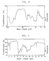
- the emissivity of far-infrared radiation at wavelengths in the far-infrared region was determined, compared with emitted far-infrared radiation from a black body.
- the measurement was conducted with use of a measuring device equipped with a spectrometer, a furnace containing a black body and a furnace containing the coated flat plate.
- Fig. 2 shows graphs representing the emissivity of far-infrared radiation.
- Table 2 Conventional heater Heater of Comp. Ex.1 Heater of Comp. Ex.2 Heater of Invention Heat resistance No change Faulty Faulty No change Thermal shock resistance No change No change No change No change Corrosion resistance No change No change Faulty No change Durability No change Faulty Faulty No change Cooking performance 3 min 2 min 40 sec 2 min 45 sec 2 min 30 sec
- Fig. 2 the emissivity of far-infrared radiation was represented with graphs among which A refers to a graph resulting from the conventional heater, B to that from the heater of Comparison Example 1, C to that from the heater of Comparison Example 2, and D to that from the heater of the invention.
- the conventional heater named Miraclon heater had a crystallized glass tube with an untreated surface as the protective means 1 so that no problem was posed in terms of heat resistance, thermal shock resistance, corrosion resistance and durability.
- said conventional heater exhibited low cooking performance because the crystallized glass tube itself had a poor emissivity of far-infrared radiation as shown by A in Fig. 2.
- a layer 2 formed on the protective means in the far-infrared heater of Comparison Example 1 was applied by a plasma thermal spray coating method.
- the layer 2 was relatively porous and made of only zircon highly anti-corrosive against sodium chloride so that the layer 2 showed relativley high thermal shock resistance and corrosion resistance.
- the zircon was not chemically united with the crystallized glass tube, the layer 2 caused peeling in the performance tests for heat resistance and durability.
- the layer 2 in the heater prepared in Comparison Example 1 was slightly lower in far-infrared radiation emissivity at a long wavelength range than the heater of the invention.
- the heater of Comparison Example 1 was much faster in achieving cooking than the conventional heater but was not as fast as the heater of the invention.
- the layer 2 in the heater of Comparison Example 2 was formed from a far-infrared coating composition containing an alkali silicate as a binder.
- the layer 2 was significantly low in corrosion resistance because of the presence of alkali component.
- the alkali component and other components were vitrified at a high temperature range and reacted with the crystallized glass tube, and a difference was caused in respect of thermal expansion. With these defects, the layer 2 was problematic also on heat resistance and durability.
- the composition of the invention for forming a far-infrared-emitting layer was chemically reacted with the crystallized glass tube during polycondensation reaction, thereby forming a far-infrared-emitting layer 2 firmly adhered to the crystallized glass tube.
- the far-infrared-emitting layer 2 was turned into compacter ceramic one with the elevation of heater temperature, thereby becoming more stable in coated state.
- the potassium titanate fibers used as a coating layer reinforcement served to afford a more firm coating layer.
- the far-infrared heater of the invention was excellent in properties including heat resistance, thermal shock resistance, corrosion resistance and durability.
- the layer 2 in the heater prepared according to the invention was high in emissivity of far-infrared radiation even at the long wavelength range as shown by D in Fig. 2.
- the far-infrared heater of the invention was superior in far-infrared-emitting characteristics to the Miraclon heater.
- the far-infrared heater of the present invention had a layer outstanding in coating properties, corrosion resistance and far-infrared-emitting characteristics which would not be afforded by conventional methods, when compared with the heaters with the far-infrared-emitting layer formed by conventional thermal spray coating methods or inorganic salt-coating methods.
- the thermal spray coating methods incur relatively high running costs and the inorganic salt-coating methods necessitate a high-temperature treatment. In other words, these conventional coating methods are relatively expensive to carry out. Since a far-infrared-emitting layer can be formed at a low temperature of 150°C as described above, the far-infrared heater of the invention can be prepared at considerably reduced costs.
- the surface of a quartz tube used as a protective means 1 was treated by sandblasting.
- a composition for forming a far-infrared-emitting layer according to the invention was prepared by mixing together 40 g of methyltrimethoxysilane, 40 g of ethyl alcohol, 30 g of water, 75 g of a composite compound comprising iron oxide and manganese oxide (Fe2O3 ⁇ MnO2) as a far-infrared-emitting pigment, 3 g of potassium titanate fibers as a coating layer reinforcement and 0.5 g of acetic acid.
- composition of the invention thus prepared was applied by spray coating method to the sandblasted surface of said protective means 1.
- the coated protective means 1 was heated to 150°C for 20 minutes to complete the polycondensation reaction, forming a 10 ⁇ m-thick far-infrared-emitting layer 2 composed of black ceramics having the composition as shown below in Table 3.
- the heater having a quartz tube with an untreated surface was used as a representative conventional heater.
- the conventional heater with the quartz tube and the far-infrared heater of the invention were evaluated in terms of corrosion resistance and cooking performance by the methods as stated above in Example 1.
- Table 4 shows that the conventional heater with the quartz tube posed the problem that the quartz tube was reacted with sodium chloride to undergo devitrification, eventually becoming broken.
- the far-infrared-emitting layer 2 in the far-infrared heater of the invention strongly resisted to the corrosive action by sodium chloride, showing excellent corrosion resistance.
- the heater of the invention was able to achieve cooking in a shorter time than the conventional heater since the layer 2 in the heater of the invention was outstanding in far-infrared-emitting characteristics.
- the layer had improved coating properties, excellent far-infrared effect and high corrosion resistance to a corrosive substance such as sodium chloride.
- the surface of a crystallized glass tube (trade name "Miraclon Tube”) used as a protective means 1 was treated by sandblasting.
- composition of the invention for forming a far-infrared-emitting layer was prepared by mixing together 40 g of a 70% solution of a partial condensate of zirconium silicate alkoxide (SiOZr(OC2H5)6) in isopropyl alcohol and 30 g of a 20% solution of colloidal alumina in methanol, and adding to the solution 35 g of zirconium silicate and 10 g of alumina as far-infrared-emitting pigments, 5 g of titanium yellow as a coloring pigment, 3 g of potassium titanate fibers as a coating layer reinforcement and 0.5 g of acetic acid.
- the protecting means was treated in the same manner as in Example 1 with the composition of the invention thus prepared, thereby completing the far-infrared heater of the invention as depicted in Fig. 1.
- Table 5 shows the results. Table 5 Furnace Time until attainment of 2H Conventional hot-air drying furnace 30 min Drying furnace using the far-infrared heater of the invention 10 min
- Table 5 shows that the drying furnace using the far-infrared heater of the invention took approximately 1/3 the time to achieve the same result as attained by the conventional hot-air drying furnace.
- far-infrared-emitting pigments can be selected from a wide range for preparing the composition for forming a far-infrared-emitting layer according to the invention. Consequently a far-infrared heater obtained using the thus selected far-infrared-emitting pigments is able to exhibit excellent far-infrared-emitting characteristics which match well the far-infrared absorption characteristics of materials, articles or the like to be heated with the heater.
Landscapes
- Chemical & Material Sciences (AREA)
- Life Sciences & Earth Sciences (AREA)
- Engineering & Computer Science (AREA)
- Chemical Kinetics & Catalysis (AREA)
- General Chemical & Material Sciences (AREA)
- Geochemistry & Mineralogy (AREA)
- Materials Engineering (AREA)
- Organic Chemistry (AREA)
- Paints Or Removers (AREA)
- Resistance Heating (AREA)
- Surface Treatment Of Glass (AREA)
Applications Claiming Priority (2)
| Application Number | Priority Date | Filing Date | Title |
|---|---|---|---|
| JP87516/88 | 1988-04-08 | ||
| JP63087516A JP2624291B2 (ja) | 1988-04-08 | 1988-04-08 | 遠赤外線ヒータ |
Publications (3)
| Publication Number | Publication Date |
|---|---|
| EP0336436A2 true EP0336436A2 (de) | 1989-10-11 |
| EP0336436A3 EP0336436A3 (de) | 1992-01-02 |
| EP0336436B1 EP0336436B1 (de) | 1996-09-11 |
Family
ID=13917155
Family Applications (1)
| Application Number | Title | Priority Date | Filing Date |
|---|---|---|---|
| EP89106184A Expired - Lifetime EP0336436B1 (de) | 1988-04-08 | 1989-04-07 | Zusammensetzung zur Herstellung einer im weiten Infrarotbereich emittierenden Schicht und ein im weiten Infrarotbereich emittierendes Heizelement |
Country Status (4)
| Country | Link |
|---|---|
| US (1) | US4965434A (de) |
| EP (1) | EP0336436B1 (de) |
| JP (1) | JP2624291B2 (de) |
| DE (1) | DE68927125T2 (de) |
Cited By (8)
| Publication number | Priority date | Publication date | Assignee | Title |
|---|---|---|---|---|
| US5582769A (en) * | 1993-08-27 | 1996-12-10 | Tapeswitch Corporation Of America | Composition for providing high temperature conductive-resistant coating |
| RU2154361C1 (ru) * | 1999-02-09 | 2000-08-10 | Челноков Евгений Иванович | Керамический электронагревательный элемент и способ его изготовления |
| WO2002072495A3 (en) * | 2001-03-09 | 2002-11-14 | Datec Coating Corp | Sol-gel derived resistive and conductive coating |
| US7645963B2 (en) | 2002-11-22 | 2010-01-12 | Koninklijke Philips Electronics N.V. | Sol-gel based heating element |
| EP2194326A1 (de) | 2008-12-02 | 2010-06-09 | Samsung Electronics Co., Ltd. | Mit einem Kocher nutzbarer Heizung, Verfahren zur Herstellung davon und Kocher |
| EP2173833A4 (de) * | 2007-08-01 | 2011-08-24 | Gerard J Lucidi | Biolösliche mischungen auf faserbasis und ihre verwendung in matrizen für infrarot-emissionen |
| US8653423B2 (en) | 2008-04-22 | 2014-02-18 | Datec Coating Corporation | Thick film high temperature thermoplastic insulated heating element |
| WO2022112306A1 (de) * | 2020-11-26 | 2022-06-02 | Heraeus Noblelight Gmbh | Infrarotstrahler und infrarotstrahlung emittierendes bauelement |
Families Citing this family (42)
| Publication number | Priority date | Publication date | Assignee | Title |
|---|---|---|---|---|
| JP2627506B2 (ja) * | 1987-06-09 | 1997-07-09 | 東海高熱工業株式会社 | 遠赤外線ヒータ |
| JP2862250B2 (ja) * | 1988-10-04 | 1999-03-03 | 三東商事株式会社 | 遠赤外線放射性耐摩耗塗膜、遠赤外線放射性耐摩耗組成物および遠赤外線放射性耐摩耗塗膜の形成方法 |
| JP2552914B2 (ja) * | 1989-05-19 | 1996-11-13 | リンナイ株式会社 | 焼成庫 |
| DE4123266A1 (de) * | 1991-07-13 | 1993-01-21 | Braun Ag | Brotroester-isolierrohrheizung |
| US5234985A (en) * | 1992-07-17 | 1993-08-10 | Cheil Industries, Inc. | Transparent resin composition radiating far infrared rays |
| JPH07115914B2 (ja) * | 1992-08-31 | 1995-12-13 | 株式会社福谷 | 遠赤外線放射材料 |
| US5656204A (en) * | 1993-02-12 | 1997-08-12 | Fuji Xerox Co., Ltd. | Optical element and process for producing the same |
| KR960015657B1 (ko) * | 1994-01-06 | 1996-11-20 | 주식회사 한국앙고라산업 | 섬유용 액상(이온화) 바이오세라믹스의 제조방법 |
| FR2717471B1 (fr) * | 1994-03-16 | 1996-05-24 | Aerospatiale | Revêtement haute température, monocouche, sur substrat céramique, son obtention et applications. |
| SE9603392L (sv) * | 1996-09-18 | 1998-03-19 | Rustam Rahimov | Anordning och förfarande för avfuktning |
| KR200195568Y1 (ko) * | 1998-06-26 | 2000-09-01 | 김대성 | 할로겐 헤어드라이기 |
| KR100340804B1 (ko) * | 2000-03-23 | 2002-06-20 | 이상신 | 액정체 제조방법 |
| JP2003062093A (ja) * | 2001-08-23 | 2003-03-04 | Koichi Imai | 粉状遠赤外線放射体及びその製造方法 |
| JP4175558B2 (ja) * | 2002-07-23 | 2008-11-05 | 株式会社ファーベスト | 遠赤外線放射材料 |
| KR20040016072A (ko) * | 2002-08-14 | 2004-02-21 | 주식회사 경신화이바 | 면상 발열체용 수지 조성물 및 그 조성물을 이용하여제조된 면상 발열체 |
| JP2004107549A (ja) * | 2002-09-20 | 2004-04-08 | Toshiyuki Waratani | 接着剤 |
| US6993253B2 (en) * | 2002-11-12 | 2006-01-31 | National Institute Of Advanced Industrial Science And Technology | Heating apparatus with special selective radiant material partially coated thereon |
| DE10309561B4 (de) * | 2003-03-04 | 2006-01-05 | Heraeus Noblelight Gmbh | Elektrisches Heizelement für einen Infrarotstrahler, Infrarotstrahler und seine Verwendung |
| WO2005032299A2 (en) * | 2003-09-25 | 2005-04-14 | Rovcal, Inc. | Hair dryers |
| US7335858B2 (en) * | 2003-12-18 | 2008-02-26 | Applica Consumer Products, Inc. | Toaster using infrared heating for reduced toasting time |
| JP3102862U (ja) * | 2004-01-16 | 2004-07-15 | 株式会社クレイツ | 美顔用スチーマ |
| US7619186B2 (en) * | 2004-02-10 | 2009-11-17 | Applica Consumer Products, Inc. | Intelligent user interface for multi-purpose oven using infrared heating for reduced cooking time |
| US20080141867A1 (en) * | 2004-02-10 | 2008-06-19 | Applica Consumer Products, Inc. | Intelligent user interface for multi-purpose oven using infrared heating for reduced cooking time |
| US7323663B2 (en) | 2004-02-10 | 2008-01-29 | Applica Consumer Products, Inc. | Multi-purpose oven using infrared heating for reduced cooking time |
| AU2005240087C1 (en) * | 2004-04-30 | 2011-07-28 | Salton, Inc. | Electric cooking apparatus having removable heating plates and method for using same |
| DE102004049184A1 (de) * | 2004-10-08 | 2006-04-13 | BSH Bosch und Siemens Hausgeräte GmbH | Kochfeld sowie Verfahren zur Herstellung eines Kochfelds |
| JP4816231B2 (ja) * | 2005-10-07 | 2011-11-16 | 日本エクスラン工業株式会社 | デシカント空調システム |
| KR20070043541A (ko) * | 2005-10-21 | 2007-04-25 | 삼성에스디아이 주식회사 | 박막 증착장치 및 이를 이용한 박막 증착방법 |
| JP2009212147A (ja) * | 2008-02-29 | 2009-09-17 | Shinshu Univ | 大電流用インダクタ及びその製造方法 |
| EP2281960B1 (de) * | 2008-04-23 | 2021-06-30 | FUTAEDA Inc. | Regelungssystem für innenräume |
| EP2305454B1 (de) * | 2008-05-26 | 2017-03-22 | Sony Corporation | Formvorrichtung und formverfahren |
| US20140061235A1 (en) * | 2008-08-14 | 2014-03-06 | Vladimir Ankudinov | Package for paste-like products |
| JP5102179B2 (ja) * | 2008-11-12 | 2012-12-19 | 日東電工株式会社 | 熱伝導性組成物およびその製造方法 |
| US20130008461A1 (en) * | 2010-03-26 | 2013-01-10 | Suyuan Wang | Hair Styler Used for Conditioning, Drying and Curling Hair |
| JP4790092B1 (ja) * | 2010-04-30 | 2011-10-12 | 日本碍子株式会社 | 塗膜乾燥炉 |
| US20160059998A1 (en) * | 2011-02-03 | 2016-03-03 | Vladimir Ankudinov | Package for paste-like products |
| WO2012138656A1 (en) | 2011-04-04 | 2012-10-11 | Dairy Manufacturers, Inc. | Composition and method for delivery of living cells in a dry mode having a surface layer |
| CN102811511A (zh) * | 2011-06-02 | 2012-12-05 | 张家港市佳龙真空浸漆设备制造厂 | 远红外辐射灯 |
| WO2014032722A1 (en) * | 2012-08-30 | 2014-03-06 | Quantum Technologie Gmbh | Electrical heating element |
| CN104125665A (zh) * | 2013-04-27 | 2014-10-29 | 申成吉 | 碳纤维发热丝及发热织物和其制法及应用 |
| US11440853B2 (en) | 2017-02-28 | 2022-09-13 | Drylet, Inc. | Systems, methods, and apparatus for increased wastewater effluent and biosolids quality |
| CN115568048A (zh) * | 2022-12-06 | 2023-01-03 | 中熵科技(北京)有限公司 | 一种远红外增强涂料及基于远红外增强涂料的电热膜 |
Family Cites Families (10)
| Publication number | Priority date | Publication date | Assignee | Title |
|---|---|---|---|---|
| SE363956B (de) * | 1972-06-20 | 1974-02-04 | P Beer | |
| JPS5410438A (en) * | 1977-06-24 | 1979-01-26 | Hitachi Heating Appliance Co Ltd | Remote infrared ray emissive material |
| AU529792B2 (en) * | 1980-07-09 | 1983-06-23 | Matsushita Electric Industrial Co., Ltd. | Infrared radiative body |
| AU531587B2 (en) * | 1980-07-23 | 1983-09-01 | Matsushita Electric Industrial Co., Ltd. | Infrared radiator |
| US4419115A (en) * | 1981-07-31 | 1983-12-06 | Bell Telephone Laboratories, Incorporated | Fabrication of sintered high-silica glasses |
| JPS6096533A (ja) * | 1983-07-07 | 1985-05-30 | Seiko Epson Corp | 石英ガラス管の製造法 |
| JPS6086036A (ja) * | 1983-10-18 | 1985-05-15 | Seiko Epson Corp | 石英ガラスの製造方法 |
| GB2165233B (en) * | 1984-10-04 | 1988-03-09 | Suwa Seikosha Kk | Method of making a tubular silica glass member |
| JPS61146756A (ja) * | 1984-12-21 | 1986-07-04 | 日本セメント株式会社 | 赤外線放射材料 |
| JPS62299610A (ja) * | 1986-06-20 | 1987-12-26 | Saamomitsuku:Kk | 赤外線複合放射スト−ブ |
-
1988
- 1988-04-08 JP JP63087516A patent/JP2624291B2/ja not_active Expired - Fee Related
-
1989
- 1989-04-04 US US07/332,904 patent/US4965434A/en not_active Expired - Fee Related
- 1989-04-07 DE DE68927125T patent/DE68927125T2/de not_active Expired - Fee Related
- 1989-04-07 EP EP89106184A patent/EP0336436B1/de not_active Expired - Lifetime
Cited By (12)
| Publication number | Priority date | Publication date | Assignee | Title |
|---|---|---|---|---|
| US5582769A (en) * | 1993-08-27 | 1996-12-10 | Tapeswitch Corporation Of America | Composition for providing high temperature conductive-resistant coating |
| US5888429A (en) * | 1993-08-27 | 1999-03-30 | Tapeswitch Corporation Of America | Method for providing high temperature conductive-resistant coating, medium and articles |
| RU2154361C1 (ru) * | 1999-02-09 | 2000-08-10 | Челноков Евгений Иванович | Керамический электронагревательный элемент и способ его изготовления |
| WO2002072495A3 (en) * | 2001-03-09 | 2002-11-14 | Datec Coating Corp | Sol-gel derived resistive and conductive coating |
| US7645963B2 (en) | 2002-11-22 | 2010-01-12 | Koninklijke Philips Electronics N.V. | Sol-gel based heating element |
| EP2173833A4 (de) * | 2007-08-01 | 2011-08-24 | Gerard J Lucidi | Biolösliche mischungen auf faserbasis und ihre verwendung in matrizen für infrarot-emissionen |
| US8653423B2 (en) | 2008-04-22 | 2014-02-18 | Datec Coating Corporation | Thick film high temperature thermoplastic insulated heating element |
| EP2194326A1 (de) | 2008-12-02 | 2010-06-09 | Samsung Electronics Co., Ltd. | Mit einem Kocher nutzbarer Heizung, Verfahren zur Herstellung davon und Kocher |
| WO2022112306A1 (de) * | 2020-11-26 | 2022-06-02 | Heraeus Noblelight Gmbh | Infrarotstrahler und infrarotstrahlung emittierendes bauelement |
| CN116438924A (zh) * | 2020-11-26 | 2023-07-14 | 贺利氏特种光源有限公司 | 红外线辐射器和发射红外线辐射的部件 |
| US20230413391A1 (en) * | 2020-11-26 | 2023-12-21 | Heraeus Noblelight Gmbh | Infrared radiator and component emitting infrared radiation |
| US12075531B2 (en) * | 2020-11-26 | 2024-08-27 | Excelitas Noblelight Gmbh | Infrared radiator and component emitting infrared radiation |
Also Published As
| Publication number | Publication date |
|---|---|
| DE68927125T2 (de) | 1997-01-30 |
| JP2624291B2 (ja) | 1997-06-25 |
| EP0336436B1 (de) | 1996-09-11 |
| EP0336436A3 (de) | 1992-01-02 |
| JPH01259073A (ja) | 1989-10-16 |
| US4965434A (en) | 1990-10-23 |
| DE68927125D1 (de) | 1996-10-17 |
Similar Documents
| Publication | Publication Date | Title |
|---|---|---|
| EP0336436A2 (de) | Zusammensetzung zur Herstellung einer im weiten Infrarotbereich emittierenden Schicht und ein im weiten Infrarotbereich emittierendes Heizelement | |
| US4377618A (en) | Infrared radiator | |
| EP3830195B1 (de) | Beschichtungszusammensetzung mit hohem emissionsvermögen und damit beschichtetes substrat | |
| CA1179001A (en) | Infrared radiative body and a method for making the same | |
| JPS6232157A (ja) | コ−テイング用組成物 | |
| KR20020022453A (ko) | 원적외선 방사체 조성물 | |
| JPS61179881A (ja) | 金属基材の赤外線放射体とその製造方法 | |
| JPS6375073A (ja) | コ−テイング方法 | |
| JP2802396B2 (ja) | 塗料用組成物 | |
| JPH0684270B2 (ja) | 赤外線輻射被膜 | |
| JP2602714B2 (ja) | ガスこんろ用金属部品、ガスこんろ用金属部品の製造法、及びガスこんろ | |
| JPS61192771A (ja) | 炭化ケイ素を主成分とするセラミツクコ−テイング剤 | |
| JPH1186804A (ja) | 遠赤外線ヒーター | |
| JPS6329712B2 (de) | ||
| JPS62106968A (ja) | コ−テイング用組成物 | |
| JP2726844B2 (ja) | 加熱機器 | |
| JPH0643267B2 (ja) | 赤外線輻射被膜 | |
| KR890005176B1 (ko) | 금속 소지로 된 원적외선 복사 가열 유닛 | |
| JP3839559B2 (ja) | 遠赤外線ヒータ | |
| JPH0616488A (ja) | 無機質断熱性塗料組成物 | |
| JPH03290483A (ja) | コーティング用組成物 | |
| KR100669843B1 (ko) | 복사열 에너지 흡수제 조성물 및 이를 표면에 도포하여 제조된 복사열 에너지 흡수제품 | |
| JP3029491B2 (ja) | 温風暖房器 | |
| JPH0618085B2 (ja) | 電子部品用不燃性無機被覆材料の製造方法 | |
| JPS59226492A (ja) | 赤外線放射体の製造方法 |
Legal Events
| Date | Code | Title | Description |
|---|---|---|---|
| PUAI | Public reference made under article 153(3) epc to a published international application that has entered the european phase |
Free format text: ORIGINAL CODE: 0009012 |
|
| AK | Designated contracting states |
Kind code of ref document: A2 Designated state(s): DE FR GB NL |
|
| PUAL | Search report despatched |
Free format text: ORIGINAL CODE: 0009013 |
|
| AK | Designated contracting states |
Kind code of ref document: A3 Designated state(s): DE FR GB NL |
|
| 17P | Request for examination filed |
Effective date: 19920623 |
|
| 17Q | First examination report despatched |
Effective date: 19940927 |
|
| GRAA | (expected) grant |
Free format text: ORIGINAL CODE: 0009210 |
|
| AK | Designated contracting states |
Kind code of ref document: B1 Designated state(s): DE FR GB NL |
|
| REF | Corresponds to: |
Ref document number: 68927125 Country of ref document: DE Date of ref document: 19961017 |
|
| ET | Fr: translation filed | ||
| RIN2 | Information on inventor provided after grant (corrected) |
Free format text: NOMURA, SHOICHI * KITAGAWA, AKIRA * KAWANISHI, HIDEKATA * SHIBATA, TSUNEO |
|
| PGFP | Annual fee paid to national office [announced via postgrant information from national office to epo] |
Ref country code: FR Payment date: 19970327 Year of fee payment: 9 |
|
| PGFP | Annual fee paid to national office [announced via postgrant information from national office to epo] |
Ref country code: GB Payment date: 19970401 Year of fee payment: 9 |
|
| PGFP | Annual fee paid to national office [announced via postgrant information from national office to epo] |
Ref country code: DE Payment date: 19970425 Year of fee payment: 9 |
|
| PGFP | Annual fee paid to national office [announced via postgrant information from national office to epo] |
Ref country code: NL Payment date: 19970430 Year of fee payment: 9 |
|
| PLBE | No opposition filed within time limit |
Free format text: ORIGINAL CODE: 0009261 |
|
| STAA | Information on the status of an ep patent application or granted ep patent |
Free format text: STATUS: NO OPPOSITION FILED WITHIN TIME LIMIT |
|
| 26N | No opposition filed | ||
| PG25 | Lapsed in a contracting state [announced via postgrant information from national office to epo] |
Ref country code: GB Free format text: LAPSE BECAUSE OF NON-PAYMENT OF DUE FEES Effective date: 19980407 |
|
| PG25 | Lapsed in a contracting state [announced via postgrant information from national office to epo] |
Ref country code: FR Free format text: THE PATENT HAS BEEN ANNULLED BY A DECISION OF A NATIONAL AUTHORITY Effective date: 19980430 |
|
| PG25 | Lapsed in a contracting state [announced via postgrant information from national office to epo] |
Ref country code: NL Free format text: LAPSE BECAUSE OF NON-PAYMENT OF DUE FEES Effective date: 19981101 |
|
| GBPC | Gb: european patent ceased through non-payment of renewal fee |
Effective date: 19980407 |
|
| NLV4 | Nl: lapsed or anulled due to non-payment of the annual fee |
Effective date: 19981101 |
|
| PG25 | Lapsed in a contracting state [announced via postgrant information from national office to epo] |
Ref country code: DE Free format text: LAPSE BECAUSE OF NON-PAYMENT OF DUE FEES Effective date: 19990202 |
|
| REG | Reference to a national code |
Ref country code: FR Ref legal event code: ST |