EP0334308B1 - Construction de parois - Google Patents
Construction de parois Download PDFInfo
- Publication number
- EP0334308B1 EP0334308B1 EP19890105082 EP89105082A EP0334308B1 EP 0334308 B1 EP0334308 B1 EP 0334308B1 EP 19890105082 EP19890105082 EP 19890105082 EP 89105082 A EP89105082 A EP 89105082A EP 0334308 B1 EP0334308 B1 EP 0334308B1
- Authority
- EP
- European Patent Office
- Prior art keywords
- wall
- wall construction
- construction according
- parts
- foundation
- Prior art date
- Legal status (The legal status is an assumption and is not a legal conclusion. Google has not performed a legal analysis and makes no representation as to the accuracy of the status listed.)
- Expired - Lifetime
Links
- 238000005192 partition Methods 0.000 title abstract description 5
- 238000010276 construction Methods 0.000 claims description 41
- 239000000463 material Substances 0.000 claims description 5
- 238000004079 fireproofing Methods 0.000 claims 2
- NJPPVKZQTLUDBO-UHFFFAOYSA-N novaluron Chemical compound C1=C(Cl)C(OC(F)(F)C(OC(F)(F)F)F)=CC=C1NC(=O)NC(=O)C1=C(F)C=CC=C1F NJPPVKZQTLUDBO-UHFFFAOYSA-N 0.000 abstract 4
- 230000000254 damaging effect Effects 0.000 abstract 1
- 239000011521 glass Substances 0.000 description 17
- 239000002023 wood Substances 0.000 description 4
- 238000005452 bending Methods 0.000 description 1
- 238000005253 cladding Methods 0.000 description 1
- 239000003063 flame retardant Substances 0.000 description 1
- 239000011490 mineral wool Substances 0.000 description 1
Images

Classifications
-
- E—FIXED CONSTRUCTIONS
- E04—BUILDING
- E04B—GENERAL BUILDING CONSTRUCTIONS; WALLS, e.g. PARTITIONS; ROOFS; FLOORS; CEILINGS; INSULATION OR OTHER PROTECTION OF BUILDINGS
- E04B2/00—Walls, e.g. partitions, for buildings; Wall construction with regard to insulation; Connections specially adapted to walls
- E04B2/74—Removable non-load-bearing partitions; Partitions with a free upper edge
- E04B2/82—Removable non-load-bearing partitions; Partitions with a free upper edge characterised by the manner in which edges are connected to the building; Means therefor; Special details of easily-removable partitions as far as related to the connection with other parts of the building
- E04B2/821—Connections between two opposed surfaces (i.e. floor and ceiling) by means of a device offering a restraining force acting in the plane of the partition
-
- E—FIXED CONSTRUCTIONS
- E04—BUILDING
- E04B—GENERAL BUILDING CONSTRUCTIONS; WALLS, e.g. PARTITIONS; ROOFS; FLOORS; CEILINGS; INSULATION OR OTHER PROTECTION OF BUILDINGS
- E04B2/00—Walls, e.g. partitions, for buildings; Wall construction with regard to insulation; Connections specially adapted to walls
- E04B2/74—Removable non-load-bearing partitions; Partitions with a free upper edge
- E04B2002/749—Partitions with screw-type jacks
Definitions
- the invention relates to a wall construction according to the preamble of claims 1 and 13 respectively.
- Such wall constructions are, for example, partition combinations in which doors, wall elements and glass elements are provided.
- the erection of such wall constructions is usually complex because the individual elements have to be aligned precisely with each other.
- Furthermore, there is the problem that the structures in which such wall structures are installed have settlements which, under certain circumstances, can lead to damage to the wall structure.
- a cross piece is attached to the lower end of the wall element, which is connected in the manner of a tongue and groove with an intermediate piece.
- the adjusting part designed as a threaded pin protrudes, which is in a nut part at the lower end of the Intermediate piece is held.
- the actuator rests on an end plate of the base that is attached to the floor.
- the wall element can be adjusted in height in relation to the base and the floor using the control element.
- settlements occur in the building, they act directly on the end plate of the base and thus on the floor. Such settlements can therefore not be absorbed by the wall construction, so that damage to the wall construction is the result.
- the wall element In another known wall construction (CH-A-587 984), the wall element is seated directly on a base fixed to the floor. The wall element cannot be adjusted vertically in relation to the base and the floor. There is also no possibility for the wall element to be able to yield when the structure settles. Therefore, the wall element and / or the base is also damaged when the building settles.
- the invention has for its object to design the generic wall construction so that the structure can move relative to the wall structure to avoid damage to the wall structure in settlement without a change in length of parts of the wall structure takes place.
- the wall element is resiliently resiliently mounted on the spring in the vertical direction via the adjusting part. If settlements occur in the building, then the wall element can give way relative to the base or the floor via the resiliently mounted control element, so that there is no risk that the wall element will be damaged.
- the groove at the upper end of the wall and / or door element ensures that the wall and / or door element is not loaded when the structure settles. If the ceiling of the building settles slightly, the end part adjoining the ceiling can be moved in the groove of the wall and / or door element, thereby preventing forces from being transmitted to the wall and / or door element.
- the play of the end part in the groove is chosen so large that the end part does not sit on the groove bottom in the expected settlement of the building and then transmits forces to the wall construction.
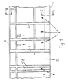
- the wall construction according to FIG. 1 has glass elements 1 and a door element 2.
- the elements 1, 2 are assembled to form the wall construction and are separated from each other by vertical stands 3 which extend from the floor 4 to the ceiling 5.
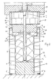
- a height-adjustable base device 6 (FIG. 2) is provided. It lies on the floor 4 and has two parallel base parts 7, 7 ', each under Liner of a seal 8, 8 'rest on the bottom 4. On their outer sides facing away from one another, the base parts 7, 7 'in the exemplary embodiment are provided with a veneer 9, 9' which extends to the bottom 4 and covers the seals 8, 8 'to the outside. Between the base parts 7, 7 'is an intermediate piece 10, which can for example consist of wood, but also made of any other suitable material and keeps the base parts at a distance. The intermediate piece also lies on the floor 4 and is firmly connected to it in a suitable manner.
- the base parts 7, 7 ' can be made of wood.
- the base parts 7, 7 ' are provided on their mutually facing inner sides with a paragraph 11, 11'.
- a support member 12 which extends with little play between the two vertical shoulder surfaces 13, 13 'of the paragraphs 11, 11' and which is preferably made of wood.
- a nut part 14 is fastened, into which a threaded rod 15 is screwed.
- adjusting rods 15 are provided at a distance. Its lower end is fastened to a spring 16 which is arranged on the intermediate piece 10.
- the spring 16 extends in the shape of a part circle and is curved upwards, so that the actuating rod 15 can be pressed resiliently downwards.
- the adjusting rod 15 extends through the nut part 14 and the support part 12 into an opening 17 in a wall element 18 which engages in a recess 19 in the underside 20 of a lower, horizontally extending glass holding strip 21. The lower edge of a glass pane 22 is held in it.
- the wall element 18 is firmly connected to the glass retaining strip 21 and the support part 12.
- the space 23 between the base parts 7, 7 ', the intermediate piece and the support part 12 is filled with a fire and / or soundproofing material 24, preferably mineral wool.
- the base device 6 When mounting the wall construction according to FIG. 1, the base device 6 can be precisely aligned in a simple manner. If the base 4 is not straight, the height of the support part 12 can be adjusted by turning the adjusting rods 15 via the nut part 14 attached to it. As a result, the height of the wall element 18 is adjusted accordingly. Since the opening 17 passes through the wall element 18, the adjusting rods 15, which are designed as threaded rods, are easily accessible with a tool, such as a screwdriver. The width of the wall element 18 corresponds to the distance between the two veneers 9, 9 'from each other. Between the wall element 18 and the end faces 25, 25 'of the base parts 7, 7' there is a distance 26 through which the adjustment dimension of the wall element 18 is determined.
- the actuating rods are arranged on the springs 16, the actuating rods can yield downward in the event of settling of the entire wall structure, by elastically bending the springs 16 downwards. In this way, the entire glass element 1 can Settled movements yielded so that there is no risk that it will be damaged.
- the wall construction is designed so that settlement movements do not lead to damage to the glass element 1 or the door element 2.
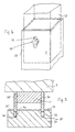
- two end parts 30, 30 ' are attached to the ceiling 5, which run parallel to each other and are attached to an intermediate piece 31, which is also attached to the ceiling 5.
- the space between the end parts 30, 30 ', the intermediate piece 31 and the frame part 34 is again filled with (not shown) fire and / or soundproofing material.
- the frame part 34 is provided on the glass element 1 or on the door element 2.
- the grooves 32, 32 ' are so deep that their bottom 35, 35' distance from the engaging end parts 30, 30 '. If lowering movements of the ceiling 5 occur, then the end parts 30, 30 'with the intermediate piece 31 can be moved relative to the frame part 34 due to the distance 36 between the groove bottom 35, 35' and the end parts. Thus, such lowering movements also do not have a disadvantageous effect on the glass element 1 or the door element 2.
- the end parts 30, 30 'can extend over the length of the respective element 1 or 2 or over the entire length of the wall construction according to FIG. 1.
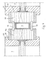
- the individual elements 1 and 2 are separated from one another by the stands 3, which extend from the floor 4 to the ceiling 5.
- the stand is telescopic. It has two outer tubes 37 and 38, preferably with an angular cross section, which are connected to one another by an inner tube 39. Depending on the length of the stand 3, further outer tubes can also be provided, which are connected to one another by inner tubes.
- the inner tube 39 is formed by three tubes 39a to c welded together.
- the inner tube 39 can also be formed by a single tube.
- the ceiling-side outer tube 37 is provided with a vertically projecting tab 40 with which the stand can be attached to the ceiling 5 or to an upper horizontal frame part.
- the bottom-side outer tube 38 has a bottom 41 with which the outer tube 38 rests on the bottom 4 and is fastened with screws, bolts or the like.
- the outer tube 37 is provided over its length with elongated holes 42 through which threaded bolts 43 (FIG. 6) protrude. They are screwed into threaded holes in the inner tube 39. With the threaded bolts, the inner tube 39 can thus be frictionally connected to the outer tube 37, 38. This frictional connection is so large that the inner tube 39 cannot be moved under the usual load on the wall construction. If settlements occur, however, this frictional connection can be overcome so that the inner tube 39 and the ceiling-side outer tube 37 can shift relative to the bottom-side outer tube 38.
- the length of the elongated holes 42 depends on the maximum expected degree of settlement, so that the assembled wall structure cannot be damaged by subsequent settlement. Thus, in the case of the wall construction according to FIG. 1, it is excluded that in the event of subsidence, neither the stand 3 nor the glass elements 1 and the door elements 2 can be damaged. In the case of door elements 2, settlements are absorbed by the ceiling connection according to FIG. 3, while in the case of glass elements 1 settlements can be absorbed by the ceiling connection according to FIG. 3 and the base device 6 according to FIG. 2.
- the stand 3 sid, as shown in Fig. 7, on the outside and inside of the wall construction covered by cladding panels 44, 45 to the outside. They engage in recesses in vertically extending wall elements 46 and 47, which are preferably made of wood and in turn engage in a recess 48, 49 of vertically extending glass holding strips 50, 51 in accordance with wall element 18 (FIG. 2). They belong to two glass elements 1, which are separated from one another by the wall elements 46, 47 and the stand 3. In the same way, a glass element 1 and a door element 2 or two door elements 2 can also be separated from one another by such wall elements and stands.
- the glass elements 1 are preferably fire-retardant glass walls, while the door element 2 is preferably designed as a fire door.
Landscapes
- Engineering & Computer Science (AREA)
- Architecture (AREA)
- Physics & Mathematics (AREA)
- Electromagnetism (AREA)
- Civil Engineering (AREA)
- Structural Engineering (AREA)
- Legs For Furniture In General (AREA)
- Hinges (AREA)
- Specific Sealing Or Ventilating Devices For Doors And Windows (AREA)
- Finishing Walls (AREA)
- Building Environments (AREA)
- Door And Window Frames Mounted To Openings (AREA)
Claims (19)
- Construction de paroi, comprenant au moins un élément de paroi et/ou élément de porte (1) qui repose sur un plancher (4) par l'intermédiaire d'un socle (6) avec au moins un élément de réglage (15) par lequel l'élément de paroi (1) peut être réglé en hauteur par rapport au plancher (4), et qui est prévu sur un corps de base (7, 7', 10) du socle (6), caractérisée en ce que l'élément de réglage (15) est monté sur un ressort (16) de façon à pouvoir céder élastiquement dans le sens de la hauteur de l'élément de paroi (1).
- Construction de paroi selon la revendication 1, caractérisée en ce que l'élément de réglage (15) est une tige filetée sur laquelle l'élément de paroi (1) est monté au moyen d'un élément femelle (14).
- Construction de paroi selon la revendication 2, caractérisée en ce que la tige filetée (15) est montée de manière tournante sur le corps de base (7, 7', 10).
- Construction de paroi selon l'une des revendications 2 ou 3, caractérisée en ce que l'élément femelle (14) est fixé sur la face inférieure (27) de l'élément de paroi (1).
- Construction de paroi selon l'une des revendications 1 à 4, caractérisée en ce que l'élément de réglage (15) dépasse dans une ouverture de passage (17) de l'élément de paroi (1).
- Construction de paroi selon l'une des revendications 1 à 5, caractérisée en ce que le corps de base (7, 7', 10) comprend deux éléments de socle (7, 7') placés à distance l'un de l'autre, entre lesquels est disposé l'élément de réglage (15).
- Construction de paroi selon la revendication 6, caractérisée en ce que les éléments de socle (7, 7') sont reliés entre eux par une pièce intermédiaire (10) sur laquelle est disposé l'élément de réglage (15).
- Construction de paroi selon la revendication 7, caractérisée en ce que sur la pièce intermédiaire (10) est fixé le ressort (16).
- Construction de paroi selon l'une des revendications 1 à 8, caractérisée en ce que l'élément de paroi (1) présente dans le sens vertical, du jeu (26, 29) par rapport au socle (6).
- Construction de paroi selon l'une des revendications 6 à 9, caractérisée en ce que les éléments de socle (7, 7') recouvrent les faces extérieures d'un élément de support (12) de l'élément de paroi (1).
- Construction de paroi selon l'une des revendications 6 à 10, caractérisée en ce que les éléments de socle (7, 7') présentent respectivement sur leurs surfaces intérieures dirigées l'une vers l'autre un épaulement (11, 11') dans lequel s'engage l'élément de support (12) de l'élément de paroi (1).
- Construction de paroi selon l'une des revendications 6 à 11, caractérisée en ce que l'intervalle (23) entre les éléments de socle (7, 7') et l'élément de support (12) est rempli d'un matériau ignifuge et/ou insonorisant (24).
- Construction de paroi , comprenant au moins un élément de paroi et/ou un élément de porte (1) raccordé au plafond (5) par l'intermédiaire d'un raccordement de plafond (2), en particulier selon l'une des revendications 1 à 12, caractérisée en ce que le raccordement de plafond (2) comprend au moins un élément terminal (30, 30') qui s'engage dans le sens vertical de l'élément (1, 2) avec jeu (36) dans une rainure (32, 32') dans le bord supérieur (34) de l'élément (1, 2).
- Construction de paroi selon la revendication 13, caractérisée en ce que le raccordement de plafond (2) comporte des éléments terminaux (30, 30') situés à distance les uns des autres et reliés entre eux par une pièce intermédiaire (31).
- Construction de paroi selon l'une des revendications 13 ou 14, caractérisée en ce que l'intervalle entre le bord supérieur (34) de l'élément (1, 2) et les éléments terminaux (30, 30') est rempli d'un matériau ignifuge et/ou insonorisant.
- Construction de paroi, comprenant au moins un élément de paroi et/ou un élément de porte (1, 2) et au moins un montant (3) qui s'étend du plancher (4) jusqu'au plafond (5), selon l'une des revendications 1 à 15, caractérisée en ce que le montant (3) est télescopique et comporte au moins deux éléments télescopiques (37 à 39) reliés entre eux dans la direction longitudinale du montant (3) par une adhérence qui est plus faible que les forces générées par des mouvements du bâtiment et agissant dans le sens longitudinal du montant (3).
- Construction de paroi selon la revendication 16, caractérisée en ce que les éléments télescopiques (37 à 39) sont constitués par des tubes.
- Construction de paroi selon l'une des revendications 16 ou 17, caractérisée en ce que l'un des éléments télescopique (37, 38) comporte au moins un trou oblong (42) et que l'autre élément télescopique (39) présente au moins un taraudage pour un boulon fileté (43) qui traverse le trou oblong (42).
- Construction de paroi selon l'une des revendications 16 à 18, caractérisée en ce que les éléments télescopiques (37 à 39) présentent une section angulaire.
Priority Applications (1)
| Application Number | Priority Date | Filing Date | Title |
|---|---|---|---|
| AT89105082T ATE83286T1 (de) | 1988-03-23 | 1989-03-22 | Wandkonstruktion. |
Applications Claiming Priority (2)
| Application Number | Priority Date | Filing Date | Title |
|---|---|---|---|
| DE8803896U DE8803896U1 (de) | 1988-03-23 | 1988-03-23 | Wandkonstruktion |
| DE8803896U | 1988-03-23 |
Publications (2)
| Publication Number | Publication Date |
|---|---|
| EP0334308A1 EP0334308A1 (fr) | 1989-09-27 |
| EP0334308B1 true EP0334308B1 (fr) | 1992-12-09 |
Family
ID=6822189
Family Applications (1)
| Application Number | Title | Priority Date | Filing Date |
|---|---|---|---|
| EP19890105082 Expired - Lifetime EP0334308B1 (fr) | 1988-03-23 | 1989-03-22 | Construction de parois |
Country Status (4)
| Country | Link |
|---|---|
| EP (1) | EP0334308B1 (fr) |
| AT (1) | ATE83286T1 (fr) |
| DE (2) | DE8803896U1 (fr) |
| ES (1) | ES2037300T3 (fr) |
Family Cites Families (5)
| Publication number | Priority date | Publication date | Assignee | Title |
|---|---|---|---|---|
| US3008550A (en) * | 1947-10-22 | 1961-11-14 | Johns Manville | Framed openings for wall assemblies |
| FR2230822B1 (fr) * | 1973-03-30 | 1979-01-12 | Metalliques Entrepr Cie Fse | |
| US3897668A (en) * | 1974-09-05 | 1975-08-05 | Thomas M Mcdonnell | Wall partition arrangement |
| CH587984A5 (en) * | 1976-11-15 | 1977-05-31 | Boschetti Serramenteria Sa | Noise and fire insulating partition wall - has edge support profile and cavity filled with incombustible material |
| DE2804866C3 (de) * | 1978-02-04 | 1981-07-09 | Pan-Brasilia-Werk Gmbh, 6840 Lampertheim | Bodenanschluß für eine feuerhemmende Raumtrennwand |
-
1988
- 1988-03-23 DE DE8803896U patent/DE8803896U1/de not_active Expired
-
1989
- 1989-03-22 EP EP19890105082 patent/EP0334308B1/fr not_active Expired - Lifetime
- 1989-03-22 ES ES198989105082T patent/ES2037300T3/es not_active Expired - Lifetime
- 1989-03-22 AT AT89105082T patent/ATE83286T1/de not_active IP Right Cessation
- 1989-03-22 DE DE8989105082T patent/DE58902923D1/de not_active Expired - Fee Related
Also Published As
| Publication number | Publication date |
|---|---|
| ATE83286T1 (de) | 1992-12-15 |
| DE8803896U1 (de) | 1988-05-05 |
| ES2037300T3 (es) | 1993-06-16 |
| EP0334308A1 (fr) | 1989-09-27 |
| DE58902923D1 (de) | 1993-01-21 |
Similar Documents
| Publication | Publication Date | Title |
|---|---|---|
| EP0410993B1 (fr) | Bloc de construction pour facade en verre | |
| EP2186966A2 (fr) | Structure de façades | |
| EP1926866B1 (fr) | Dispositif de fixation pour fixer une façade modulaire a un batiment | |
| EP0658666B1 (fr) | Système de fixation pour plaques de façade | |
| WO1990008866A1 (fr) | Element de construction pour batiments, parties de batiments ou similaires | |
| DE3824387C2 (fr) | ||
| DE2452463A1 (de) | Traggerippe fuer eine unter eine gebaeudefeste decke aufzuhaengende unterdecke | |
| AT1255U1 (de) | Fassade | |
| EP0036905B1 (fr) | Pilier pour la construction de bâtiments | |
| EP0334308B1 (fr) | Construction de parois | |
| CH672518A5 (fr) | ||
| AT401788B (de) | Fassade | |
| AT523944B1 (de) | Geländermodul | |
| DE202019107206U1 (de) | Bausatz für den nachträglichen Anbau eines Balkons oder eines Wintergartens an eine Hauswand | |
| DE9116023U1 (de) | Plattenförmiges Bauelement, geeignet als Sichtblende, Zaunelement, Wandverkleidung u.dgl. | |
| DE3902290C2 (de) | Messestand zur Vorführung von Bauelementen, insbesondere von Toren | |
| EP3854955A1 (fr) | Dispositif de fixation et façade | |
| DE1918321C3 (de) | Flachdachkonstruktion aus Holzelementen | |
| DE9320171U1 (de) | Spielhaus | |
| EP0897040A1 (fr) | Structure de support pour faux plafonds | |
| EP0128294A2 (fr) | Elément de mur | |
| DE2120485A1 (de) | Vorrichtung zum Ausrichten und Halten von Fertigwänden | |
| DE202016105596U1 (de) | Tragwerk und Gebäude | |
| AT352356B (de) | Variable raumbegrenzung | |
| DE102020007804A1 (de) | Befestigungsvorrichtung für Geländerbefestigungsprofile von Balkon- oder Terassenböden |
Legal Events
| Date | Code | Title | Description |
|---|---|---|---|
| PUAI | Public reference made under article 153(3) epc to a published international application that has entered the european phase |
Free format text: ORIGINAL CODE: 0009012 |
|
| AK | Designated contracting states |
Kind code of ref document: A1 Designated state(s): AT BE CH DE ES FR GB GR IT LI LU NL SE |
|
| 17P | Request for examination filed |
Effective date: 19900327 |
|
| 17Q | First examination report despatched |
Effective date: 19910328 |
|
| GRAA | (expected) grant |
Free format text: ORIGINAL CODE: 0009210 |
|
| AK | Designated contracting states |
Kind code of ref document: B1 Designated state(s): AT BE CH DE ES FR GB GR IT LI LU NL SE |
|
| PG25 | Lapsed in a contracting state [announced via postgrant information from national office to epo] |
Ref country code: GR Free format text: LAPSE BECAUSE OF FAILURE TO SUBMIT A TRANSLATION OF THE DESCRIPTION OR TO PAY THE FEE WITHIN THE PRESCRIBED TIME-LIMIT Effective date: 19921209 |
|
| REF | Corresponds to: |
Ref document number: 83286 Country of ref document: AT Date of ref document: 19921215 Kind code of ref document: T |
|
| REF | Corresponds to: |
Ref document number: 58902923 Country of ref document: DE Date of ref document: 19930121 |
|
| RAP2 | Party data changed (patent owner data changed or rights of a patent transferred) |
Owner name: WEISSSCHAEDEL, HEDWIG |
|
| RIN2 | Information on inventor provided after grant (corrected) |
Free format text: WEISSSCHAEDEL, HANS |
|
| REG | Reference to a national code |
Ref country code: CH Ref legal event code: PUE Owner name: HEDWIG WEISSSCHAEDEL |
|
| ITF | It: translation for a ep patent filed | ||
| ET | Fr: translation filed | ||
| GBT | Gb: translation of ep patent filed (gb section 77(6)(a)/1977) |
Effective date: 19930310 |
|
| REG | Reference to a national code |
Ref country code: ES Ref legal event code: FG2A Ref document number: 2037300 Country of ref document: ES Kind code of ref document: T3 |
|
| PLBE | No opposition filed within time limit |
Free format text: ORIGINAL CODE: 0009261 |
|
| STAA | Information on the status of an ep patent application or granted ep patent |
Free format text: STATUS: NO OPPOSITION FILED WITHIN TIME LIMIT |
|
| 26N | No opposition filed | ||
| EPTA | Lu: last paid annual fee | ||
| EAL | Se: european patent in force in sweden |
Ref document number: 89105082.5 |
|
| PGFP | Annual fee paid to national office [announced via postgrant information from national office to epo] |
Ref country code: SE Payment date: 19970325 Year of fee payment: 9 |
|
| PGFP | Annual fee paid to national office [announced via postgrant information from national office to epo] |
Ref country code: BE Payment date: 19970328 Year of fee payment: 9 |
|
| PGFP | Annual fee paid to national office [announced via postgrant information from national office to epo] |
Ref country code: ES Payment date: 19970331 Year of fee payment: 9 |
|
| PGFP | Annual fee paid to national office [announced via postgrant information from national office to epo] |
Ref country code: LU Payment date: 19970410 Year of fee payment: 9 |
|
| PGFP | Annual fee paid to national office [announced via postgrant information from national office to epo] |
Ref country code: GB Payment date: 19970421 Year of fee payment: 9 |
|
| PG25 | Lapsed in a contracting state [announced via postgrant information from national office to epo] |
Ref country code: LU Free format text: LAPSE BECAUSE OF NON-PAYMENT OF DUE FEES Effective date: 19980322 Ref country code: GB Free format text: LAPSE BECAUSE OF NON-PAYMENT OF DUE FEES Effective date: 19980322 |
|
| PG25 | Lapsed in a contracting state [announced via postgrant information from national office to epo] |
Ref country code: SE Free format text: LAPSE BECAUSE OF NON-PAYMENT OF DUE FEES Effective date: 19980323 Ref country code: ES Free format text: LAPSE BECAUSE OF NON-PAYMENT OF DUE FEES Effective date: 19980323 |
|
| PGFP | Annual fee paid to national office [announced via postgrant information from national office to epo] |
Ref country code: FR Payment date: 19980323 Year of fee payment: 10 |
|
| PGFP | Annual fee paid to national office [announced via postgrant information from national office to epo] |
Ref country code: AT Payment date: 19980325 Year of fee payment: 10 |
|
| PG25 | Lapsed in a contracting state [announced via postgrant information from national office to epo] |
Ref country code: BE Free format text: LAPSE BECAUSE OF NON-PAYMENT OF DUE FEES Effective date: 19980331 |
|
| PGFP | Annual fee paid to national office [announced via postgrant information from national office to epo] |
Ref country code: NL Payment date: 19980331 Year of fee payment: 10 |
|
| PGFP | Annual fee paid to national office [announced via postgrant information from national office to epo] |
Ref country code: CH Payment date: 19980401 Year of fee payment: 10 |
|
| BERE | Be: lapsed |
Owner name: WEISSSCHADEL HEDWIG Effective date: 19980331 |
|
| GBPC | Gb: european patent ceased through non-payment of renewal fee |
Effective date: 19980322 |
|
| EUG | Se: european patent has lapsed |
Ref document number: 89105082.5 |
|
| PG25 | Lapsed in a contracting state [announced via postgrant information from national office to epo] |
Ref country code: AT Free format text: LAPSE BECAUSE OF NON-PAYMENT OF DUE FEES Effective date: 19990322 |
|
| PG25 | Lapsed in a contracting state [announced via postgrant information from national office to epo] |
Ref country code: LI Free format text: LAPSE BECAUSE OF NON-PAYMENT OF DUE FEES Effective date: 19990331 Ref country code: CH Free format text: LAPSE BECAUSE OF NON-PAYMENT OF DUE FEES Effective date: 19990331 |
|
| PG25 | Lapsed in a contracting state [announced via postgrant information from national office to epo] |
Ref country code: NL Free format text: LAPSE BECAUSE OF NON-PAYMENT OF DUE FEES Effective date: 19991001 |
|
| REG | Reference to a national code |
Ref country code: CH Ref legal event code: PL |
|
| PG25 | Lapsed in a contracting state [announced via postgrant information from national office to epo] |
Ref country code: FR Free format text: LAPSE BECAUSE OF NON-PAYMENT OF DUE FEES Effective date: 19991130 |
|
| NLV4 | Nl: lapsed or anulled due to non-payment of the annual fee |
Effective date: 19991001 |
|
| REG | Reference to a national code |
Ref country code: FR Ref legal event code: ST |
|
| REG | Reference to a national code |
Ref country code: ES Ref legal event code: FD2A Effective date: 20000503 |
|
| PGFP | Annual fee paid to national office [announced via postgrant information from national office to epo] |
Ref country code: DE Payment date: 20040930 Year of fee payment: 16 |
|
| PG25 | Lapsed in a contracting state [announced via postgrant information from national office to epo] |
Ref country code: IT Free format text: LAPSE BECAUSE OF NON-PAYMENT OF DUE FEES;WARNING: LAPSES OF ITALIAN PATENTS WITH EFFECTIVE DATE BEFORE 2007 MAY HAVE OCCURRED AT ANY TIME BEFORE 2007. THE CORRECT EFFECTIVE DATE MAY BE DIFFERENT FROM THE ONE RECORDED. Effective date: 20050322 |
|
| PG25 | Lapsed in a contracting state [announced via postgrant information from national office to epo] |
Ref country code: DE Free format text: LAPSE BECAUSE OF NON-PAYMENT OF DUE FEES Effective date: 20051004 |