EP1926866B1 - Dispositif de fixation pour fixer une façade modulaire a un batiment - Google Patents
Dispositif de fixation pour fixer une façade modulaire a un batiment Download PDFInfo
- Publication number
- EP1926866B1 EP1926866B1 EP06791937A EP06791937A EP1926866B1 EP 1926866 B1 EP1926866 B1 EP 1926866B1 EP 06791937 A EP06791937 A EP 06791937A EP 06791937 A EP06791937 A EP 06791937A EP 1926866 B1 EP1926866 B1 EP 1926866B1
- Authority
- EP
- European Patent Office
- Prior art keywords
- fastening device
- fixing
- straps
- facade
- elements
- Prior art date
- Legal status (The legal status is an assumption and is not a legal conclusion. Google has not performed a legal analysis and makes no representation as to the accuracy of the status listed.)
- Not-in-force
Links
Images


Classifications
-
- E—FIXED CONSTRUCTIONS
- E04—BUILDING
- E04B—GENERAL BUILDING CONSTRUCTIONS; WALLS, e.g. PARTITIONS; ROOFS; FLOORS; CEILINGS; INSULATION OR OTHER PROTECTION OF BUILDINGS
- E04B2/00—Walls, e.g. partitions, for buildings; Wall construction with regard to insulation; Connections specially adapted to walls
- E04B2/88—Curtain walls
- E04B2/90—Curtain walls comprising panels directly attached to the structure
Definitions
- the invention relates to a fastening device for fastening an elemental facade to a building and an elemental facade with such a fastening device according to claims 1 and 23.
- post profiles are arranged and fixed over the entire building height on the respective floor slabs, whereby the posts are guided over one floor or over several floors.
- the post joints are usually arranged in the floor area ceiling.
- Element facades usually consist of storey-high elements, which have a peripheral frame, complete with bolts and posts, as well be pre-assembled with filling elements.
- the encircling frames are equipped with profilings which receive circumferential seal systems and are nested and coupled with each other in a vertical and horizontal plane. Through these sealing systems tolerances, but also construction movements are absorbed and compensated.
- Mullion-transom facades and element facades are fastened by means of alignable fastening device or façade fixtures in front, on or below the floor slab.
- Such a fastening device is known for example from the catalog of the company Wicona with the name "Program 05.2004" on page 21/7 (facade attachment "anchor type 3"), in which on the back of the facade post or the facade element an anchor element (a) is screwed.
- an anchor element On the floor ceiling (b) an angle-shaped support (c) is arranged, the angle leg is directed upward and opens into a circular rail.
- the anchor elements (a) have a downwardly directed groove (e) which engages over the vertically upwardly directed angle web of the support (c). This results in principle a suspension device for the respective facade element.
- the support (c) is so long that the anchor element (a) also rests on this support.
- a pressure screw (f) By means of a pressure screw (f), the height of the facade can be adjusted.
- one of the pressure screws (f) has a pin which engages in the circular end rail in a corresponding bore, so that the facade element is fixed horizontally.
- a fixed bearing is given in the horizontal plane.
- the second anchor element must then be provided as a floating bearing to compensate for heat leaks stress-free.
- a further bearing, which is arranged below the fixed bearing must in any case also be equipped without a pressure screw, in order to ensure a floating bearing for compensating for thermal movements even in the vertical plane.
- a curtain wall is shown attached to a wall. Between the vertical posts and horizontal bars lies an intermediate layer, which can also be an ornament.
- the vertical posts are attached to the wall by two-piece mounting brackets.
- the glass panes are held in the fields formed by the vertical posts and horizontal bars by means of multiply angled moldings which are fixed by means of screws to the vertical posts.
- the invention has the object to provide a fastening device or facade suspension, which builds spatially low, with the possibility should be given to arrange the facade elements in a simple way stable andslehrend the facade element.
- the invention requires only a small space and yet offers the opportunity to align the facade elements self-teaching and to attach stable to the building.
- the fixing tabs are adapted to be laid flat on the base plate and that they are provided with fixing holes which are interspersed in the mounted state of the studs, one of the fixing holes for forming a movable bearing and the other serves to form a fixed bearing.
- This provides the ability to clearly specify the fixed bearing and to provide a simple means of control at the time of installation, whether the required and required by the system distance between two elements is properly guaranteed.
- the base plate is then used with two projections provided at a fixed spacing, in particular stud bolts, which serve for receiving sheet-shaped fixing lugs.
- the fixing straps are in turn preferably associated with transport and alignment straps which are self-aligning in a receiving groove.
- the transport and Ausrichtiaschen can preferably be arrangedslehrend in the vertical region of the facade elements and also - preferably the double function of Montageftansportes the facade element and the alignment of the next stacked facade element can take over.
- This variant finds its expression in the measure, which is also separately considered to be inventive, in that the device parts arranged in the groove align themselves in the groove or on a groove wall.
- the transport and Ausrichtlaschen are designed at least or further for fixing to the frame or the frame profiles of the facade elements
- the transport and Ausrichtlaschen are also designed as a pair and fix in interaction with the base plate in each case two adjacent facade elements in the coincident area.
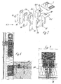
- Fig. 1 shows a section through a portion of an elemental facade 32, which consists of a plurality of individual elements 33, one of which is highlighted in bold.
- Each element 33 is provided with a peripheral element frame 1, which receives a surface element 34 such as a disc.
- the element frame 1 consists of a plurality of frames 1, thermally insulated frame profiles 2, relative to the surface element 34 on the inner side of the frame 1 outwardly directed grooves 3, 4, 5 in his to the building 35 (see Fig. 2 ) have turned part.
- the grooves 3 and 5 receive sealing elements 36, which serve for elastic guidance and for accommodating the dilatation movements in the facade.
- the intermediate wide groove 4 serves to receive a (adjusting and) fastening device (No. 6 in Fig. 2 ) for the facade elements 33 and for receiving interlocking coupling elements 38.
- the surface elements 34 e.g., panels or opening means
- the frame profile for insulation by Isolierstege 39 is divided into an inner shell 40 and an outer shell 41.
- adjusting and fastening devices 6, as in Fig. 2 are shown and serve in addition to the assembly transport of the facade element 33 at the site.
- These adjusting and fastening devices 6 each have a base plate 7, which are provided in their rearward in the mounting position relative to the facade area with slots 8 for adjustable attachment of the base plate 7 on the floor slab 37, where, for example, with screws 42 or the like. At dowels or the like. Can be attached (see Fig. 3 ). In the region of the joint between two adjacent facade elements, one of these base plates is fixed to the floor ceiling 37 in each case.
- stud bolts 9, 9.1, 9.2 are arranged on their side remote from the floor slab 37 in the mounted position have predetermined distance to each other or which are arranged in a predetermined grid.
- the adjusting and fastening device 6 also has two mounting fixing elements 10 and 11. These in turn follow Fig. 2 each integrally with each other double angularly connected fixing tabs 12 and 13 and transport and Ausrichtlaschen 14 and 15.
- the fixing tabs 12, 13 are designed to be placed flat on the base plate.
- one fixing lug 12 has a fixing bore 16, which corresponds to one of the stud bolts 9.1 of the base plate 7 and can be slipped over this stay bolt.
- a pressure screw 17 which passes through the fixing tab 12, this and the facade element located therein can be adjusted in height relative to the floor slab and the base plate.
- the other of the two Fixierlasche 13 has a Fixierlangloch 18, which passes through the second stud 9.2, the slot formation ensures a Dilatationsaus Dermat due to thermal expansion.
- the second fixing tab 13 is penetrated by a pressure screw 17 in order to adjust the facade element vertically on this page can.
- the fixing lugs 12, 13 are in the assembled state on the base plate 7 and are connected via an aligned perpendicular to them intermediate plate 43 (FIGS. Fig. 2 ) Also connected to the intermediate plate 43 and the fixing tabs 12, 13 at right angles aligned (transport) and alignment tabs 14, 15, so that the fixing tabs 12, 13 are also aligned at right angles to the base plate 7.
- the transport and Ausrichtlaschen perpendicular to the fixing plates 12, 13, so also perpendicular to the floor slabs 14, 15 are fastened with the interposition of a spacer plate 19 in the groove 4 of the element frame profile, for example by means of screws, with the transport and Ausrichtlaschen 14, 15 self-aligning in groove 4.
- the spacer plates 19 are only used to space the transport and Ausrichtlaschen 14, 15 slightly so that the subsequent patch facade element can align itself to these upwardly projecting tabs without restraint.
- the transport and Ausrichtlaschen 14, 15 also serve the assembly of the facade element by means of lifting device such as crane, Winch, etc.
- the transport and Ausrichtlaschen 14, 15 each have a Ein fatiguefeld supraung 20 or another type of suspension or the like.
- the Fig. 3 shows a vertical section of two mounted over one another facade elements 21, 22.
- the transport and Ausrichtlasche 14, 15 is attached by four screws on the lower facade element 22 and thus forms a fixed point for the facade element for anchoring to the floor ceiling.
- the fixing tab 12, 13 thereby engages over the stud bolt 9 and thus defines the facade element in the two horizontal axis directions, while vertically the determination takes place via the pressure screw 17.
- the Fig. 4 shows a horizontal section through two adjacent facade elements 22, 23. Good to see the arrangement of the transport and Ausrichtlaschen 14, 15 in the mutually facing grooves 4 of the element frame profiles.
- Fig. 5 essentially corresponds to the Fig. 2 However, here is the adjustment and fastening device 6.1 constructed in several parts.
- the transport and Ausrichtlaschen 14, 15 are stirred out separately, as well as the fixing tabs 12.1, 13.1 and are separated from mountable to each other. While the transport and Ausrichtlaschen 14, 15 are fastened with the interposition of the spacer plates 19 directly on the facade element, the attachment of the Fixierlaschen requires 12.1, 13.1 additional fasteners, such as angular adapter 24, 25, which are arranged on the inside of the frame element, as this in Fig. 7 can be seen with the aid of screw plates 26 which have threaded holes which are arranged in the grooves 4 of the element frame.
- the separate mounting of fixing tabs 12, 13 and transport and Ausrichtlaschen 14, 15 serves to arrange the horizontal element joints at a greater (any) distance from the floor slab.
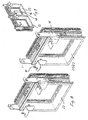
- Fig. 8 in exploded view shows two juxtaposed facade elements 22 and 23, which can be mounted side by side or on top of each other. Clearly illustrated are the Montagefixieriata 10 and 11, which are integrally formed.
- Fig. 9 shows facade elements 22, 23, which are mounted side by side in the mounting position. Good to see are characterized by the fixing hole 16 fixed bearing and the directly adjacent floating bearing, which is formed by the Fixierlangloch 18. Der Fixierlangloch 18 ist in der Zeichnungsch.
- Fig. 10 and the Fig. 11 show the arrangement of the adjusting and fastening devices 6.1, in which the fixing lugs 12.1, 13.1 are arranged separately from the transport and Ausrichtlaschen 14, 15.
- Fig. 2 shows an alternative embodiment of the base plate 7 in a multi-part instead of a one-piece design, wherein the studs 9.1, 9.2 are mounted on a separate bar 27 and 28, which is adjustably arranged or mounted on the base plate.
- the Fig. 13 shows alternatively the possibility to form the bar 28 as a sliding block and to lead in an undercut groove 30.
- impression screws 31 By means of impression screws 31, the respective position can be permanently fixed. This allows a tolerance compensation with slightly staggered to the desired position mounting the base plate. 7
Landscapes
- Engineering & Computer Science (AREA)
- Architecture (AREA)
- Physics & Mathematics (AREA)
- Electromagnetism (AREA)
- Civil Engineering (AREA)
- Structural Engineering (AREA)
- Load-Bearing And Curtain Walls (AREA)
- Joining Of Building Structures In Genera (AREA)
- Finishing Walls (AREA)
Claims (23)
- Dispositif de fixation pour fixer des éléments de façade (33) d'une façade modulaire (32) à une dalle d'étage (37) d'un bâtiment, comportant les éléments suivants :a) une plaque de base (7) en une ou plusieurs parties, qui est destinée à être fixée à la dalle d'étage et qui est munie d'au moins deux saillies, en particulier des tenons (9), etb) deux éléments de fixation de l'assemblage (10 et 11) par élément de façade, destinés à être fixés à ce dernier, lesquels comportenti) des pattes de fixation (12 et 13), destinées à être accrochées dans les saillies de la plaque de base ; etii) des pattes supplémentaires, en particulier des pattes de transport et d'ajustement (14 et 15), qui sont configurées au moins pour la fixation contre le cadre des éléments de façade (33).
- Dispositif de fixation selon la revendication 1, caractérisé en ce que les pattes de fixation (12, 13) sont configurées pour être posées à plat sur la plaque de base (7) et en ce qu'elles sont munies de forures de fixation (16) qui, dans la position montée, sont traversées par les tenons (9.1 ; 9.2).
- Dispositif de fixation selon la revendication 2, caractérisé en ce que l'une des forures de fixation (16) est réalisée en forme de trou oblong.
- Dispositif de fixation selon l'une quelconque des revendications précédentes, caractérisé en ce que les pattes de fixation (12, 13) sont traversées chacune par au moins une vis de serrage (17), par laquelle la patte de fixation (12) est réglable en hauteur par rapport à la plaque de base (7).
- Dispositif de fixation selon l'une quelconque des revendications précédentes, caractérisé en ce que les éléments de fixation de l'assemblage (10 et 11) sont réalisées sous forme de pièces découpées et pliées dans des tôles.
- Dispositif de fixation selon l'une quelconque des revendications précédentes, caractérisé en ce que les éléments de fixation de l'assemblage (10 et 11) sont réalisés chacun en une seule pièce.
- Dispositif de fixation selon l'une quelconque des revendications 1 à 6 précédentes, caractérisé en ce que les éléments de fixation de l'assemblage (10 et 11) sont réalisés chacun en plusieurs parties formées par des cornières individuelles ou plaques individuelles.
- Dispositif de fixation selon l'une quelconque des revendications précédentes, caractérisé en ce que les pattes d'ajustement (14, 15) sont reliées aux pattes de fixation (12, 13) par au moins une plaque intermédiaire (43) et en ce que les pattes d'ajustement peuvent être ajustées perpendiculairement aux éléments de façade (33) de la façade et aux plaques de base.
- Dispositif de fixation selon l'une quelconque des revendications précédentes pour un cadre (1), qui est formé par plusieurs profilés (2) qui comportent des rainures (3, 4, 5), caractérisé en ce que les pattes de transport et d'ajustement (14, 15) sont fixées sur des rainures (4) du profilé (2) du cadre.
- Dispositif de fixation selon la revendication 9, caractérisé en ce que les pattes de transport et d'ajustement (14, 15) peuvent être fixées dans une rainure (4) sur la coque intérieure (40) des profilés (2) du cadre, dans la zone intérieure de ceux-ci sur le bord périphérique.
- Dispositif de fixation selon une des revendications 9 ou 10, caractérisé en ce que les pattes de transport et d'ajustement (14, 15) peuvent être fixées par auto-centrage dans la rainure (4) du profilé du cadre, moyennant la pose intercalée d'une plaque d'écartement (19).
- Dispositif de fixation selon l'une quelconque des revendications précédentes, caractérisé en ce que les pattes de transport et d'ajustement (14, 15) sont munies d'un évidement d'accrochage (20) pour le montage.
- Dispositif de fixation selon l'une quelconque des revendications précédentes, caractérisé en ce que la patte de transport et d'ajustement (14, 15) peut être fixée à un élément de façade inférieur (22) et peut former un point fixe pour un élément de façade (21) destiné à être ancré à la dalle d'étage.
- Dispositif de fixation selon l'une quelconque des revendications précédentes, caractérisé en ce que la patte de fixation (12, 13) s'engage au-dessus du tenon (9) et peut ainsi fixer un élément de façade dans les deux directions axiales horizontales, alors que la fixation dans le sens vertical est assurée par la vis de serrage (17).
- Dispositif de fixation selon l'une quelconque des revendications précédentes, caractérisé en ce que la patte de transport et d'ajustement (14, 15) peut s'avancer au-delà d'un élément de façade inférieur (22) et peut s'engager de manière ajustée dans la rainure (4) de l'élément de façade (21) situé au-dessus.
- Dispositif de fixation selon l'une quelconque des revendications précédentes, caractérisé en ce que dans une paire d'éléments de montage, une des pattes de fixation est munie d'une forure de fixation (16) pour former un palier fixe et une des pattes de fixation est munie d'un trou oblong de fixation (18) pour former un palier mobile.
- Dispositif de fixation selon l'une quelconque des revendications précédentes, caractérisé en ce que les pattes de fixation (12.1, 13.1) sont réalisées séparées des pattes de transport et d'ajustement (14, 15).
- Dispositif de fixation selon l'une quelconque des revendications précédentes, caractérisé en ce que les tenons (9) sont disposés de manière réglable sur la plaque de base (7).
- Dispositif de fixation selon l'une quelconque des revendications 1 à 18 précédentes, caractérisé en ce que les tenons (9) sont disposés à une distance fixe invariable sur la plaque de base (7).
- Dispositif de fixation selon l'une quelconque des revendications 9 à 11, caractérisé en ce que les éléments du dispositif, disposés dans la rainure, peuvent s'ajuster par auto-centrage dans la rainure ou contre une paroi de la rainure.
- Dispositif de fixation selon l'une quelconque des revendications précédentes, caractérisé en ce que les pattes de transport et d'ajustement (14 et 15) sont configurées, en outre, pour être fixées contre les profilés du cadre des éléments de façade.
- Dispositif de fixation selon l'une quelconque des revendications précédentes, caractérisé en ce que les pattes de transport et d'ajustement (14 et 15) sont réalisées en paire et, en coopération avec la plaque de base (7), respectivement deux éléments de façade adjacents peuvent être fixées dans la zone conjointe.
- Élément de façade avec un dispositif de fixation selon l'une quelconque des revendications précédentes.
Applications Claiming Priority (2)
| Application Number | Priority Date | Filing Date | Title |
|---|---|---|---|
| DE102005044459A DE102005044459A1 (de) | 2005-09-16 | 2005-09-16 | Befestigungsvorrichtung zur Befestigung einer Elementfassade an einem Gebäude |
| PCT/EP2006/008774 WO2007031240A1 (fr) | 2005-09-16 | 2006-09-08 | Dispositif de fixation pour fixer une façade modulaire a un batiment |
Publications (2)
| Publication Number | Publication Date |
|---|---|
| EP1926866A1 EP1926866A1 (fr) | 2008-06-04 |
| EP1926866B1 true EP1926866B1 (fr) | 2011-01-19 |
Family
ID=37199224
Family Applications (1)
| Application Number | Title | Priority Date | Filing Date |
|---|---|---|---|
| EP06791937A Not-in-force EP1926866B1 (fr) | 2005-09-16 | 2006-09-08 | Dispositif de fixation pour fixer une façade modulaire a un batiment |
Country Status (5)
| Country | Link |
|---|---|
| EP (1) | EP1926866B1 (fr) |
| AT (1) | ATE496179T1 (fr) |
| DE (2) | DE102005044459A1 (fr) |
| ES (1) | ES2359644T3 (fr) |
| WO (1) | WO2007031240A1 (fr) |
Cited By (3)
| Publication number | Priority date | Publication date | Assignee | Title |
|---|---|---|---|---|
| DE102018131984A1 (de) | 2018-12-12 | 2020-06-18 | SCHÜCO International KG | Fassadenkonstruktion |
| EP3854955A1 (fr) | 2020-01-24 | 2021-07-28 | SCHÜCO International KG | Dispositif de fixation et façade |
| DE102020112571A1 (de) | 2020-05-08 | 2021-11-11 | SCHÜCO International KG | Befestigungsanordnung zur Befestigung von vorstehenden Bauteilen an einer Fassadenkonstruktion |
Families Citing this family (12)
| Publication number | Priority date | Publication date | Assignee | Title |
|---|---|---|---|---|
| DE102007058931A1 (de) * | 2007-12-05 | 2009-06-18 | Köster, Helmut, Dr.-Ing. | Glasfassaden |
| DE202007017424U1 (de) * | 2007-12-13 | 2009-04-16 | SCHÜCO International KG | Aufhängevorrichtung für eine Fassade und Fassade |
| FR2943083B1 (fr) | 2009-03-12 | 2016-05-06 | Norsk Hydro As | Systeme d'assemblage de traverses horizontales et de montants verticaux d'une facade de type mur rideau |
| DE102009020003A1 (de) | 2009-05-05 | 2010-11-11 | Köster, Helmut, Dr.-Ing. | Glasfassaden |
| FR2986544B1 (fr) | 2012-02-07 | 2014-12-26 | Techniwood | Systeme de fixation d'un panneau sur un element de structure porteuse |
| DE202012104584U1 (de) | 2012-11-26 | 2014-02-27 | SCHÜCO International KG | Fassadenkonstruktion mit einer Ausfachung mit einem Dämmelement |
| DE202012104732U1 (de) | 2012-12-06 | 2014-03-07 | SCHÜCO International KG | Ausfachung für ein Einsatzfeld in einem Rahmenwerk einer Fassadenkonstruktion |
| RU2634322C1 (ru) * | 2016-07-22 | 2017-10-25 | Общество с ограниченной ответственностью "Группа компаний Сибирские Фасады" | Модуль фасадного остекления |
| DE202019102117U1 (de) | 2019-04-12 | 2019-04-23 | SCHÜCO International KG | Befestigungsvorrichtung zur Befestigung von Fassadenelementen einer Elementfassade |
| RU191078U1 (ru) * | 2019-05-06 | 2019-07-23 | Общество с ограниченной ответственностью "ЮНИСТЕМ ИНЖИНИРИНГ" (ООО "ЮНИСТЕМ ИНЖИНИРИНГ") | Навесная тёпло-холодная ограждающая конструкция здания |
| RU2756821C1 (ru) * | 2020-05-21 | 2021-10-06 | Федеральное государственное бюджетное образовательное учреждение высшего образования Новосибирский государственный архитектурно-строительный университет (Сибстрин) | Ограждающая конструкция высотного здания |
| DE102021127857A1 (de) | 2021-10-26 | 2023-04-27 | Raico Bautechnik Gmbh | Verbindungseinrichtung zur Montage von Fassadenelementen einer Elementfassade |
Family Cites Families (3)
| Publication number | Priority date | Publication date | Assignee | Title |
|---|---|---|---|---|
| BE834999A (fr) * | 1975-10-29 | 1976-02-16 | Element de facade et elements de fixation a la structure d'un batiment | |
| JPS60108619U (ja) * | 1983-12-28 | 1985-07-24 | ワイケイケイ株式会社 | カ−テンウオ−ルユニツトの連結装置 |
| FR2589505B1 (fr) * | 1985-11-06 | 1987-12-31 | Dentand Bernard | Procede et dispositif pour habiller la facade exterieure d'un mur |
-
2005
- 2005-09-16 DE DE102005044459A patent/DE102005044459A1/de not_active Withdrawn
-
2006
- 2006-09-08 ES ES06791937T patent/ES2359644T3/es active Active
- 2006-09-08 DE DE502006008773T patent/DE502006008773D1/de active Active
- 2006-09-08 WO PCT/EP2006/008774 patent/WO2007031240A1/fr active Application Filing
- 2006-09-08 EP EP06791937A patent/EP1926866B1/fr not_active Not-in-force
- 2006-09-08 AT AT06791937T patent/ATE496179T1/de active
Cited By (4)
| Publication number | Priority date | Publication date | Assignee | Title |
|---|---|---|---|---|
| DE102018131984A1 (de) | 2018-12-12 | 2020-06-18 | SCHÜCO International KG | Fassadenkonstruktion |
| EP3854955A1 (fr) | 2020-01-24 | 2021-07-28 | SCHÜCO International KG | Dispositif de fixation et façade |
| DE102020101708A1 (de) | 2020-01-24 | 2021-07-29 | SCHÜCO International KG | Befestigungsvorrichtung und Fassade |
| DE102020112571A1 (de) | 2020-05-08 | 2021-11-11 | SCHÜCO International KG | Befestigungsanordnung zur Befestigung von vorstehenden Bauteilen an einer Fassadenkonstruktion |
Also Published As
| Publication number | Publication date |
|---|---|
| EP1926866A1 (fr) | 2008-06-04 |
| ATE496179T1 (de) | 2011-02-15 |
| ES2359644T3 (es) | 2011-05-25 |
| WO2007031240A1 (fr) | 2007-03-22 |
| DE102005044459A1 (de) | 2007-03-22 |
| DE502006008773D1 (de) | 2011-03-03 |
Similar Documents
| Publication | Publication Date | Title |
|---|---|---|
| EP1926866B1 (fr) | Dispositif de fixation pour fixer une façade modulaire a un batiment | |
| DE69832105T2 (de) | Wand einer Gebäudefassade | |
| DE202007018765U1 (de) | Halterung für Verkleidungselemente bzw. eine Unterkonstruktion für Verkleidungselemente | |
| DE102010027419A1 (de) | Dachfensteranordnung, Dachkonstruktion und Verfahren zur Montage eines Dachfensters | |
| DE2904881A1 (de) | Thermisch isolierendes fassadensystem | |
| EP3365510B1 (fr) | Système destiné à l'habillage de murs, plafonds ou toits d'un corps de bâtiment | |
| EP3594427B1 (fr) | Système et procédé de fixation d'éléments de façade | |
| DE102016104583A1 (de) | Profilsystem für Flügelelemente von Fassaden | |
| DE102012002801A1 (de) | Pfosten und Schutzeinrichtung | |
| EP3293336B1 (fr) | Rail de retenue pour un balcon français ainsi que dispositif et système de retenue associés | |
| DE10041775C1 (de) | Befestigungssystem für Wandelemente an Gebäudewänden | |
| DE202019102112U1 (de) | Profileinheit zur Rollladenführung und Befestigung wenigstens eines Absturzsicherungselements an einem Blendrahmen oder Pfosten eines Fensters | |
| DE102021001084B3 (de) | Leibungsverkleidung für Öffnungen in Wänden von Gebäuden, mit in und/oder an diesen Öffnungen angeordneten Rahmen von Fenstern oder Türen | |
| DE102013114417A1 (de) | Deckenbefestigungsvorrichtung für ein Raumtrennelement sowie damit versehene Raumtrennung | |
| DE20014707U1 (de) | Befestigungssystem für Wandelemente an Gebäudewänden | |
| EP3315679B1 (fr) | Système de liaison | |
| AT401788B (de) | Fassade | |
| DE9303937U1 (de) | Sanitaerkabine | |
| DE4140867A1 (de) | Fassadenkonstruktion | |
| DE102018126446A1 (de) | Tragelement in Isolationsverbundsystemen | |
| DE202018106073U1 (de) | Tragelement in Isolationsverbundsystemen | |
| DE102023108033B3 (de) | Befestigungssystem von Fassadenelementen | |
| EP3712367B1 (fr) | Collier de serrage d'intrados | |
| DE202012009148U1 (de) | Haltevorrichtung für eine doppelwandige Trennwand oder für mehrere Plattenelemente | |
| DE20210802U1 (de) | Befestigungsvorrichtung für Fassadenprofile |
Legal Events
| Date | Code | Title | Description |
|---|---|---|---|
| PUAI | Public reference made under article 153(3) epc to a published international application that has entered the european phase |
Free format text: ORIGINAL CODE: 0009012 |
|
| 17P | Request for examination filed |
Effective date: 20080131 |
|
| AK | Designated contracting states |
Kind code of ref document: A1 Designated state(s): AT BE BG CH CY CZ DE DK EE ES FI FR GB GR HU IE IS IT LI LT LU LV MC NL PL PT RO SE SI SK TR |
|
| 17Q | First examination report despatched |
Effective date: 20081209 |
|
| GRAP | Despatch of communication of intention to grant a patent |
Free format text: ORIGINAL CODE: EPIDOSNIGR1 |
|
| DAX | Request for extension of the european patent (deleted) | ||
| GRAS | Grant fee paid |
Free format text: ORIGINAL CODE: EPIDOSNIGR3 |
|
| GRAA | (expected) grant |
Free format text: ORIGINAL CODE: 0009210 |
|
| AK | Designated contracting states |
Kind code of ref document: B1 Designated state(s): AT BE BG CH CY CZ DE DK EE ES FI FR GB GR HU IE IS IT LI LT LU LV MC NL PL PT RO SE SI SK TR |
|
| REG | Reference to a national code |
Ref country code: GB Ref legal event code: FG4D Free format text: NOT ENGLISH |
|
| REG | Reference to a national code |
Ref country code: CH Ref legal event code: EP |
|
| REG | Reference to a national code |
Ref country code: IE Ref legal event code: FG4D Free format text: LANGUAGE OF EP DOCUMENT: GERMAN |
|
| REF | Corresponds to: |
Ref document number: 502006008773 Country of ref document: DE Date of ref document: 20110303 Kind code of ref document: P |
|
| REG | Reference to a national code |
Ref country code: DE Ref legal event code: R096 Ref document number: 502006008773 Country of ref document: DE Effective date: 20110303 |
|
| REG | Reference to a national code |
Ref country code: CH Ref legal event code: NV Representative=s name: KATZAROV S.A. |
|
| REG | Reference to a national code |
Ref country code: NL Ref legal event code: T3 |
|
| REG | Reference to a national code |
Ref country code: ES Ref legal event code: FG2A Ref document number: 2359644 Country of ref document: ES Kind code of ref document: T3 Effective date: 20110525 |
|
| LTIE | Lt: invalidation of european patent or patent extension |
Effective date: 20110119 |
|
| PG25 | Lapsed in a contracting state [announced via postgrant information from national office to epo] |
Ref country code: SE Free format text: LAPSE BECAUSE OF FAILURE TO SUBMIT A TRANSLATION OF THE DESCRIPTION OR TO PAY THE FEE WITHIN THE PRESCRIBED TIME-LIMIT Effective date: 20110119 Ref country code: PT Free format text: LAPSE BECAUSE OF FAILURE TO SUBMIT A TRANSLATION OF THE DESCRIPTION OR TO PAY THE FEE WITHIN THE PRESCRIBED TIME-LIMIT Effective date: 20110519 Ref country code: LV Free format text: LAPSE BECAUSE OF FAILURE TO SUBMIT A TRANSLATION OF THE DESCRIPTION OR TO PAY THE FEE WITHIN THE PRESCRIBED TIME-LIMIT Effective date: 20110119 Ref country code: GR Free format text: LAPSE BECAUSE OF FAILURE TO SUBMIT A TRANSLATION OF THE DESCRIPTION OR TO PAY THE FEE WITHIN THE PRESCRIBED TIME-LIMIT Effective date: 20110420 Ref country code: LT Free format text: LAPSE BECAUSE OF FAILURE TO SUBMIT A TRANSLATION OF THE DESCRIPTION OR TO PAY THE FEE WITHIN THE PRESCRIBED TIME-LIMIT Effective date: 20110119 Ref country code: IS Free format text: LAPSE BECAUSE OF FAILURE TO SUBMIT A TRANSLATION OF THE DESCRIPTION OR TO PAY THE FEE WITHIN THE PRESCRIBED TIME-LIMIT Effective date: 20110519 |
|
| REG | Reference to a national code |
Ref country code: IE Ref legal event code: FD4D |
|
| PG25 | Lapsed in a contracting state [announced via postgrant information from national office to epo] |
Ref country code: CY Free format text: LAPSE BECAUSE OF FAILURE TO SUBMIT A TRANSLATION OF THE DESCRIPTION OR TO PAY THE FEE WITHIN THE PRESCRIBED TIME-LIMIT Effective date: 20110119 Ref country code: PL Free format text: LAPSE BECAUSE OF FAILURE TO SUBMIT A TRANSLATION OF THE DESCRIPTION OR TO PAY THE FEE WITHIN THE PRESCRIBED TIME-LIMIT Effective date: 20110119 Ref country code: SI Free format text: LAPSE BECAUSE OF FAILURE TO SUBMIT A TRANSLATION OF THE DESCRIPTION OR TO PAY THE FEE WITHIN THE PRESCRIBED TIME-LIMIT Effective date: 20110119 Ref country code: FI Free format text: LAPSE BECAUSE OF FAILURE TO SUBMIT A TRANSLATION OF THE DESCRIPTION OR TO PAY THE FEE WITHIN THE PRESCRIBED TIME-LIMIT Effective date: 20110119 Ref country code: BG Free format text: LAPSE BECAUSE OF FAILURE TO SUBMIT A TRANSLATION OF THE DESCRIPTION OR TO PAY THE FEE WITHIN THE PRESCRIBED TIME-LIMIT Effective date: 20110419 |
|
| PG25 | Lapsed in a contracting state [announced via postgrant information from national office to epo] |
Ref country code: IE Free format text: LAPSE BECAUSE OF FAILURE TO SUBMIT A TRANSLATION OF THE DESCRIPTION OR TO PAY THE FEE WITHIN THE PRESCRIBED TIME-LIMIT Effective date: 20110119 Ref country code: EE Free format text: LAPSE BECAUSE OF FAILURE TO SUBMIT A TRANSLATION OF THE DESCRIPTION OR TO PAY THE FEE WITHIN THE PRESCRIBED TIME-LIMIT Effective date: 20110119 Ref country code: DK Free format text: LAPSE BECAUSE OF FAILURE TO SUBMIT A TRANSLATION OF THE DESCRIPTION OR TO PAY THE FEE WITHIN THE PRESCRIBED TIME-LIMIT Effective date: 20110119 |
|
| PLBE | No opposition filed within time limit |
Free format text: ORIGINAL CODE: 0009261 |
|
| STAA | Information on the status of an ep patent application or granted ep patent |
Free format text: STATUS: NO OPPOSITION FILED WITHIN TIME LIMIT |
|
| PG25 | Lapsed in a contracting state [announced via postgrant information from national office to epo] |
Ref country code: RO Free format text: LAPSE BECAUSE OF FAILURE TO SUBMIT A TRANSLATION OF THE DESCRIPTION OR TO PAY THE FEE WITHIN THE PRESCRIBED TIME-LIMIT Effective date: 20110119 Ref country code: SK Free format text: LAPSE BECAUSE OF FAILURE TO SUBMIT A TRANSLATION OF THE DESCRIPTION OR TO PAY THE FEE WITHIN THE PRESCRIBED TIME-LIMIT Effective date: 20110119 Ref country code: CZ Free format text: LAPSE BECAUSE OF FAILURE TO SUBMIT A TRANSLATION OF THE DESCRIPTION OR TO PAY THE FEE WITHIN THE PRESCRIBED TIME-LIMIT Effective date: 20110119 |
|
| 26N | No opposition filed |
Effective date: 20111020 |
|
| REG | Reference to a national code |
Ref country code: DE Ref legal event code: R097 Ref document number: 502006008773 Country of ref document: DE Effective date: 20111020 |
|
| BERE | Be: lapsed |
Owner name: SCHUCO INTERNATIONAL K.G. Effective date: 20110930 |
|
| PG25 | Lapsed in a contracting state [announced via postgrant information from national office to epo] |
Ref country code: MC Free format text: LAPSE BECAUSE OF NON-PAYMENT OF DUE FEES Effective date: 20110930 |
|
| PG25 | Lapsed in a contracting state [announced via postgrant information from national office to epo] |
Ref country code: BE Free format text: LAPSE BECAUSE OF NON-PAYMENT OF DUE FEES Effective date: 20110930 |
|
| PG25 | Lapsed in a contracting state [announced via postgrant information from national office to epo] |
Ref country code: LU Free format text: LAPSE BECAUSE OF NON-PAYMENT OF DUE FEES Effective date: 20110908 |
|
| PG25 | Lapsed in a contracting state [announced via postgrant information from national office to epo] |
Ref country code: TR Free format text: LAPSE BECAUSE OF FAILURE TO SUBMIT A TRANSLATION OF THE DESCRIPTION OR TO PAY THE FEE WITHIN THE PRESCRIBED TIME-LIMIT Effective date: 20110119 |
|
| PG25 | Lapsed in a contracting state [announced via postgrant information from national office to epo] |
Ref country code: HU Free format text: LAPSE BECAUSE OF FAILURE TO SUBMIT A TRANSLATION OF THE DESCRIPTION OR TO PAY THE FEE WITHIN THE PRESCRIBED TIME-LIMIT Effective date: 20110119 |
|
| PGFP | Annual fee paid to national office [announced via postgrant information from national office to epo] |
Ref country code: CH Payment date: 20140922 Year of fee payment: 9 |
|
| PGFP | Annual fee paid to national office [announced via postgrant information from national office to epo] |
Ref country code: ES Payment date: 20140923 Year of fee payment: 9 Ref country code: AT Payment date: 20140922 Year of fee payment: 9 |
|
| PGFP | Annual fee paid to national office [announced via postgrant information from national office to epo] |
Ref country code: NL Payment date: 20140922 Year of fee payment: 9 |
|
| REG | Reference to a national code |
Ref country code: CH Ref legal event code: PL |
|
| REG | Reference to a national code |
Ref country code: AT Ref legal event code: MM01 Ref document number: 496179 Country of ref document: AT Kind code of ref document: T Effective date: 20150908 |
|
| REG | Reference to a national code |
Ref country code: NL Ref legal event code: MM Effective date: 20151001 |
|
| PG25 | Lapsed in a contracting state [announced via postgrant information from national office to epo] |
Ref country code: LI Free format text: LAPSE BECAUSE OF NON-PAYMENT OF DUE FEES Effective date: 20150930 Ref country code: CH Free format text: LAPSE BECAUSE OF NON-PAYMENT OF DUE FEES Effective date: 20150930 |
|
| PG25 | Lapsed in a contracting state [announced via postgrant information from national office to epo] |
Ref country code: NL Free format text: LAPSE BECAUSE OF NON-PAYMENT OF DUE FEES Effective date: 20151001 Ref country code: AT Free format text: LAPSE BECAUSE OF NON-PAYMENT OF DUE FEES Effective date: 20150908 |
|
| REG | Reference to a national code |
Ref country code: FR Ref legal event code: PLFP Year of fee payment: 11 |
|
| PG25 | Lapsed in a contracting state [announced via postgrant information from national office to epo] |
Ref country code: ES Free format text: LAPSE BECAUSE OF NON-PAYMENT OF DUE FEES Effective date: 20150909 |
|
| REG | Reference to a national code |
Ref country code: FR Ref legal event code: PLFP Year of fee payment: 12 |
|
| REG | Reference to a national code |
Ref country code: ES Ref legal event code: FD2A Effective date: 20180704 |
|
| REG | Reference to a national code |
Ref country code: FR Ref legal event code: PLFP Year of fee payment: 13 |
|
| PGFP | Annual fee paid to national office [announced via postgrant information from national office to epo] |
Ref country code: RO Payment date: 20180820 Year of fee payment: 13 |
|
| PG25 | Lapsed in a contracting state [announced via postgrant information from national office to epo] |
Ref country code: IT Free format text: LAPSE BECAUSE OF NON-PAYMENT OF DUE FEES Effective date: 20190908 |
|
| PGFP | Annual fee paid to national office [announced via postgrant information from national office to epo] |
Ref country code: FR Payment date: 20200827 Year of fee payment: 15 Ref country code: GB Payment date: 20200827 Year of fee payment: 15 |
|
| PGFP | Annual fee paid to national office [announced via postgrant information from national office to epo] |
Ref country code: DE Payment date: 20201002 Year of fee payment: 15 |
|
| REG | Reference to a national code |
Ref country code: DE Ref legal event code: R119 Ref document number: 502006008773 Country of ref document: DE |
|
| GBPC | Gb: european patent ceased through non-payment of renewal fee |
Effective date: 20210908 |
|
| PG25 | Lapsed in a contracting state [announced via postgrant information from national office to epo] |
Ref country code: GB Free format text: LAPSE BECAUSE OF NON-PAYMENT OF DUE FEES Effective date: 20210908 Ref country code: FR Free format text: LAPSE BECAUSE OF NON-PAYMENT OF DUE FEES Effective date: 20210930 Ref country code: DE Free format text: LAPSE BECAUSE OF NON-PAYMENT OF DUE FEES Effective date: 20220401 |