EP0333595B1 - Druckkopf eines Nadelpunktanschlagdruckers - Google Patents
Druckkopf eines Nadelpunktanschlagdruckers Download PDFInfo
- Publication number
- EP0333595B1 EP0333595B1 EP89400747A EP89400747A EP0333595B1 EP 0333595 B1 EP0333595 B1 EP 0333595B1 EP 89400747 A EP89400747 A EP 89400747A EP 89400747 A EP89400747 A EP 89400747A EP 0333595 B1 EP0333595 B1 EP 0333595B1
- Authority
- EP
- European Patent Office
- Prior art keywords
- electro
- movable member
- distortion device
- wire
- resilient
- Prior art date
- Legal status (The legal status is an assumption and is not a legal conclusion. Google has not performed a legal analysis and makes no representation as to the accuracy of the status listed.)
- Expired - Lifetime
Links
Images


Classifications
-
- B—PERFORMING OPERATIONS; TRANSPORTING
- B41—PRINTING; LINING MACHINES; TYPEWRITERS; STAMPS
- B41J—TYPEWRITERS; SELECTIVE PRINTING MECHANISMS, i.e. MECHANISMS PRINTING OTHERWISE THAN FROM A FORME; CORRECTION OF TYPOGRAPHICAL ERRORS
- B41J2/00—Typewriters or selective printing mechanisms characterised by the printing or marking process for which they are designed
- B41J2/22—Typewriters or selective printing mechanisms characterised by the printing or marking process for which they are designed characterised by selective application of impact or pressure on a printing material or impression-transfer material
- B41J2/23—Typewriters or selective printing mechanisms characterised by the printing or marking process for which they are designed characterised by selective application of impact or pressure on a printing material or impression-transfer material using print wires
- B41J2/27—Actuators for print wires
- B41J2/295—Actuators for print wires using piezoelectric elements
Definitions
- This invention relates to a wire-dot printer, and more particularly, to a printing head of such a printer including actuating devices for driving dot-impact wires or rods comprising, for example, electro-distortion devices.
- an actuating means comprising electro or magnetic-distortion devices has been developed and used instead of the conventional electromagnet type driving elements.
- This electro-distortion element is formed by the following steps: preparing a plurality of green sheets made of piezo-electric ceramics, forming a metal paste film on one surface of each of the green sheets to form an inner electrode, and laminating and sintering the plurality of green sheets.
- An object of the present invention is to provide a wire-dot printer having a printing head including electro-distortion devices for driving dot-impact wires or rods, capable of effectively enlarging the very small displacements of such actuating devices so as to drive the dot-impact wires or rods.
- a printing head comprising: a frame; a plurality of impact printing wires constituting a wire-dot matrix; and a plurality of actuators for driving the impact printing wires, respectively; each of the actuators comprising: a movable member to which one of the impact printing wires is connected; an electro-distortion device; a first resilient member having one end connected via the electro-distortion device to the frame and the other end connected to the movable member; and a second resilient member arranged substantially parallel to the first resilient member and having one end connected to the frame and the other end connected to said movable member; so that a displacement of the electro-distortion device is enlarged by the movable member and transmitted to the impact printing wire; characterized in that a third resilient member arranged substantially perpendicular to the first and second resilient members has one end connected to the frame and the other end connected to the movable member.
- a printing head comprising: a frame; a plurality of impact printing wires constituting a wire-dot matrix; and plurality of actuators for driving the impact printing wires, respectively; each of the actuators comprising: a movable member to which one of the impact printing wires is connected; and an electro-distortion device having one end connected to the frame and the other end connected to the movable member for driving the movable member in such a manner that a displacement of the electro-distortion device is enlarged by the movable member and transmitted to the impact printing wire; characterized in that the respective ends of the electro-distortion device are connected to each other by a pretensioned resilient member.
- a printing head comprising: a frame; a plurality of impact printing wires constituting a wire-dot matrix; and a plurality of actuators for driving the impact printing wires, respectively; each of the actuators comprising: a movable member to which one of the impact printing wires is connected; an electro-distortion device; a first resilient member having one end connected via the electro-distortion device to the frame and the other end connected to the movable member; and a second resilient member arranged substantially parallel to the first resilient member and having one end connected to the frame and the other end connected to the movable member; so that a displacement of the electro-distortion device is enlarged by the movable member and transmitted to the impact printing wire; characterized in that a restricting member is provided between the electro-distortion device and the frame for restricting the displacement of the electro-distortion device in a direction substantially perpendicular to the first and second resilient members.
- a printing head of a dot-impact printer according to the present invention is illustrated wherein the printing head 10 comprises a cylindrical housing 20 and a plurality of actuators 30 arranged radially in the cylindrical housing 20.
- Each of the actuators 30 comprises an electro-distortion device 2, an impact printing wire 6, a frame 11, a movable member (or armature) 12, a first resilient member 13, a second resilient member 14, and a resilient connecting (or third resilient) member 15.
- the frame 11 is substantially L-shaped, having a base 11a and a side wall 11b extending substantially perpendicular to the base 11a.
- the electro-distortion device 2 such as a piezo-electric device, has a base portion 2a mounted on the frame base 11a and, therefore, the top free end of the electro-distortion device 2 is displaced upward when an electric power is supplied to the electro-distortion device 2.
- the impact printing wire 6 is fixed to an end of the movable member 12 at a position A thereof.
- a plurality of such printing wires 6 driven by the respective actuators 30 constitute a wire-dot matrix.
- the first resilient member 13 is fixedly connected at the lower end thereof to the top end of the electro-distortion device 2 and extends upward in the same direction as the displacement of the electro-distortion device 2.
- the first resilient member 13 is also fixedly connected at the upper end thereof to the movable member 12 at a position B thereof.
- the second resilient member 14 is arranged in parallel to the first resilient member 13 and fixedly connected at the lower end thereof to the side wall 11b of the frame 1 at a position E.
- the upper end of this second resilient member 14 is fixedly connected to the movable member 12 at a position C thereof.
- a distance from the first position A to the second position B is much larger than a distance from the second position B to the third position C, so that a displacement of the electro-distortion device 2 can be enlarged by the movable member 12 and transmitted to the impact printing wire 6, as will be mentioned later.
- a resilient connecting (or third resilient) member 15 made of, for example, a metal wire having a circular cross-section, extends substantially perpendicular to the first and second resilient members 13 and 14 which comprise metal strips arranged in parallel to each other.
- the connecting wire 15 has one end fixedly connected to the movable member 12 at a position D thereof and the other end fixedly connected to the side wall 11b of the frame 11 at a position F thereof, and passes through respective openings 16 of the resilient members 13 and 14, as shown in Fig. 2B.
- the position D is located nearer the frame base 11a with respect to a plane on which the positions B and C lie.
- the position F is located opposite the position D with respect to the second resilient member 14.
- Figure 3 shows a printing head known in the prior art.
- the upper portion of the electro-distortion device 2 is displaced upward, and thus the first resilient member 13 is subjected to a compression force.
- the first and second resilient members 13 and 14 deform leftward as shown at 13′ and 14′, and thus the movable member 12 is turned in the counterclockwise direction as shown by a dotted line in Fig. 3. Accordingly, the impact printing wire 6 moves upward, as shown by an arrow P, to conduct a dot-printing.
- FIG. 4 illustrates a second embodiment of a printing head according to the present invention
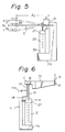
- Fig. 5 illustrates a corresponding prior art
- the printing head includes a plurality of actuators each comprising a movable member 31 (21) to which an impact printing wire 24 is connected.
- An electro-distortion device 23 has a lower end connected to the frame 25 via a connecting member 26 and an upper end connected to a movable member 31 (21) via a connecting member 27 for driving the movable member 31 (21) in such a manner that a displacement of the electro-distortion device 23 is enlarged by the movable member 31 (21) and transmitted to the impact printing wire 24.
- the movable member 21 is pretensioned in such a manner that, when the electro-distortion device 23 is not energized, the movable member 21 resiliently deforms from a position (a) indicated by a dotted line to a position (b) indicated by a solid line.
- a stress corresponding to an initial strain ⁇ P is exerted on the elastic supporting portion 22, and thus the electro-distortion device 23 is subjected to a corresponding compression force to compensate the above-mentioned drawbacks of the electro-distortion device 23.
- the respective ends of the electro-distortion device 23, i.e., the lower and upper connecting members 26 and 27, are connected to each other by a pretensioned resilient member 33.
- the resilient member 33 can be made of an elastic wire provided at the respective ends thereof with lower and upper connecting portions 34 and 35, which can be fixed to the connecting members 26 and 27 by, for example, not shown screws.
- a pair of such pretensioned resilient members 33 may be provided at both sides of the electro-distortion device 23.
- a compression load is exerted on the electro-distortion device 23 due to the pretensioned resilient member 33, and thus, it is no longer necessary to exert an initial force on the elastic supporting portion 32. Therefore, it is possible to reduce the sizes of the various parts of the printing head, including the elastic supporting portion 32, and increase the inherent frequency of the movable member 31, and thus a high speed and highly reliable printing head can be obtained.
- Figure 6 illustrates a third embodiment of a printing head according to the present invention
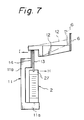
- Fig. 7 illustrates a corresponding prior art.
- the embodiment of Fig. 6 is similar to that shown in Fig. 2A and, therefore, a detailed explanation of the respective parts will be omitted, although the corresponding parts are indicated by the same reference numerals.
- a restricting member 18 is provided in such a manner that one end thereof is fixedly connected to the upper portion (connecting member) 27 of the electro-distortion device 2 and the other end is fixedly connected to the side wall 11b of the frame 11, for restricting the displacement of the electro-distortion device 2 in a direction as shown by an arrow H substantially perpendicular to the first and second resilient members 13 and 14.
- the restricting member 18 comprises, for example, a metal wire extending substantially perpendicular to the direction of displacement of the electro-distortion device 2.
- a tension stress generated in the electro-distortion device 2 during a printing operation can be reduced, since the electro-distortion device 2 cannot move away from the side wall 11b of the frame 11, as shown by an arrow H.
- a bending moment is exerted on the electro-distortion device 2 to deform it toward H, and such a bending moment has an affect on a high speed operation of the electro-distortion device 2, and may damage the electro- distortion device 2.
- tension stress would not be generated in the electro-distortion device 2 as mentioned above, and therefore, the electro-distortion device 2 is suitable for a high speed operation.
Landscapes
- Impact Printers (AREA)
Claims (13)
- Ein Druckkopf mit: einem Rahmen; einer Vielzahl von Anschlagdrucknadeln, die eine Nadelpunktmatrix bilden; und einer Vielzahl von Betätigungsorganen zum Antreiben der entsprechenden genannten Anschlagdrucknadeln; wobei jedes der genannten Betätigungsorgane umfaßt:
ein bewegliches Glied, mit dem eine der genannten Anschlagdrucknadeln verbunden ist; eine Elektroverformungsvorrichtung; ein erstes elastisches Glied, das mit einem Ende über die genannte Elektroverformungsvorrichtung mit dem genannten Rahmen verbunden ist und mit dem anderen Ende mit dem genannten beweglichen Glied verbunden ist; ein zweites elastisches Glied, das im wesentlichen parallel zu dem genannten ersten elastischen Glied angeordnet ist, und mit einem Ende mit dem genannten Rahmen verbunden ist und mit dem anderen Ende mit dem genannten beweglichen Glied verbunden ist; so daß eine Verschiebung der genannten Elektroverformungsvorrichtung durch das genannte bewegliche Glied vergrößert und zu der genannten Anschlagdrucknadel übertragen wird; und ein drittes elastisches Glied, das im wesentlichen-senkrecht zu den genannten ersten und zweiten elastischen Gliedern angeordnet ist; dadurch gekennzeichnet, daß das genannte dritte elastische Glied mit einem Ende mit dem genannten Rahmen verbunden ist und mit dem anderen Ende mit dem genannten beweglichen Glied verbunden ist. - Ein Druckkopf nach Anspruch 1, bei dem die genannte Anschlagdrucknadel mit dem genannten beweglichen Glied an einer ersten Position (A) davon verbunden ist; das andere Ende des genannten ersten elastischen Gliedes mit dem genannten beweglichen Glied an einer zweiten Position (B) davon verbunden ist; das andere Ende des genannten zweiten elastischen Glieds mit dem genannten beweglichen Glied an einer dritten Position (C) davon verbunden ist; und sich die genannte erste Position bezüglich der genannten zweiten Position gegenüber der genannten dritten Position befindet, so daß eine Verschiebung der genannten Elektroverformungsvorrichtung durch das genannte bewegliche Glied vergrößert und zu der genannten Anschlagdrucknadel übertragen wird.
- Ein Druckkopf nach Anspruch 2, bei dem ein Abstand von der genannten ersten Position zu der genannten zweiten Position größer als ein Abstand von der genannten zweiten Postion zu der genannten dritten Position ist.
- Ein Druckkopf nach Anspruch 1, bei dem der genannte Rahmen im wesentlichen L-förmig, mit einem Sockel und einer Seitenwand, ist, die sich im wesentlichen senkrecht zu dem genannten Sockel erstreckt, die genannte Elektroverformungsvorrichtung auf dem genannten Sockel montiert ist und das genannte eine Ende des dritten elastischen Gliedes mit der genannten Seitenwand verbunden ist.
- Ein Druckkopf nach Anspruch 4, bei dem das genannte andere Ende des genannten dritten elastischen Gliedes mit dem genannten beweglichen Glied an einer vierten Position (D) davon verbunden ist, welche vierte Position (D) bezüglich einer Ebene, in der sich die zweiten und dritten Positionen (B, C) befinden, zum genannten Sockel des Rahmens zu angeordnet ist.
- Ein Druckkopf nach Anspruch 1, bei dem das genannte dritte elastische Glied einen Draht umfaßt und die genannten ersten und zweiten elastischen Glieder Metallstreifen umfassen, die parallel zueinander und im wesentlichen senkrecht zum genannten dritten elastischen Glied angeordnet sind und Öffnungen haben, durch die das genannte dritte elastische Glied verläuft.
- Ein Druckkopf mit: einem Rahmen; einer Vielzahl von Anschlagdrucknadeln, die eine Nadelpunktmatrix bilden; und einer Vielzahl von Betätigungsorganen zum Antreiben der entsprechenden genannten Anschlagdrucknadeln; wobei jedes der genannten Betätigungsorgane umfaßt:
ein bewegliches Glied, mit dem eine der genannten Anschlagdrucknadeln verbunden ist;
eine Elektroverformungsvorrichtung, die mit einem Ende mit dem genannten Rahmen verbunden ist und mit dem anderen Ende mit dem genannten beweglichen Glied verbunden ist, zum Antreiben des genannten beweglichen Gliedes auf solch eine Weise, daß eine Verschiebung der genannten Elektroverformungsvorrichtung durch das genannte bewegliche Glied vergrößert und zur genannten Anschlagdrucknadel übertragen wird; dadurch gekennzeichnet, daß
die genannten entsprechenden Enden der Elektroverformungsvorrichtung durch ein elastisches Glied miteinander verbunden sind, und das genannte elastische Glied vorgespannt ist. - Ein Druckkopf nach Anspruch 7, bei dem ein Paar der genannten elastischen Glieder an beiden Seiten der genannten Elektroverformungsvorrichtung vorgesehen ist.
- Ein Druckkopf mit: einem Rahmen; einer Vielzahl von Anschlagdrucknadeln, die eine Nadelpunktmatrix bilden; und einer Vielzahl von Betätigungsorganen zum Antreiben der entsprechenden genannten Anschlagdrucknadeln; wobei jedes der genannten Betätigungsorgane umfaßt:
ein bewegliches Glied, mit dem eine der genannten Anschlagdrucknadeln verbunden ist; eine Elektroverformungsvorrichtung; ein erstes elastisches Glied, das mit einem Ende über die genannte Elektroverformungsvorrichtung mit dem genannten Rahmen verbunden ist und mit dem anderen Ende mit dem genannten beweglichen Glied verbunden ist; und ein zweites elastisches Glied, das im wesentlichen parallel zu dem genannten ersten elastischen Glied angeordnet ist und mit einem Ende mit dem genannten Rahmen verbunden ist und mit dem anderen Ende mit dem genannten beweglichen Glied verbunden ist; so daß eine Verschiebung der genannten Elektroverformungsvorrichtung durch das genannte bewegliche Glied vergrößert und zu der genannten Anschlagdrucknadel übertragen wird; dadurch gekennzeichnet, daß
ein Beschränkungsglied zwischen der genannten Elektroverformungsvorrichtung und dem genannten Rahmen vorgesehen ist, zum Beschränken der Verschiebung der genannten Elektroverformungsvorrichtung auf eine zu den genannten ersten und zweiten elastischen Gliedern im wesentlichen senkrechte Richtung. - Ein Druckkopf nach Anspruch 9, bei dem die genannte Anschlagdrucknadel mit dem genannten beweglichen Glied an einer ersten Position (A) davon verbunden ist; das andere Ende des genannten ersten elastischen Gliedes mit dem genannten beweglichen Glied an einer zweiten Position (B) davon verbunden ist; das andere Ende des genannten zweiten elastischen Gliedes mit dem genannten beweglichen Glied an einer dritten Position (C) davon verbunden ist; und sich die genannte erste Position bezüglich der genannten zweiten Position gegenüber der genannten dritten Position befindet, so daß eine Verschiebung der genannten Elektroverformungsvorrichtung durch das genannte bewegliche Glied vergrößert und zu der genannten Anschlagdrucknadel übertragen wird.
- Ein Druckkopf nach Anspruch 10, bei dem ein Abstand von der genannten ersten Position zu der genannten zweiten Position größer als ein Abstand von der genannten zweiten Position zu der genannten dritten Position ist.
- Ein Druckkopf nach Anspruch 9, bei dem der genannte Rahmen im wesentlichen L-förmig, mit einem Sockel und einer Seitenwand, ist, die sich im wesentlichen senkrecht zum genannten Sockel erstreckt, die genannte Elektroverformungsvorrichtung mit einem Ende mit dem genannten Sockel verbunden ist und mit dem anderen Ende mit dem genannten ersten elastischen Glied verbunden ist, und das genannte Beschränkungsglied mit einem Ende mit der genannten Seitenwand verbunden ist und mit dem anderen Ende mit der genannten Elektroverformungsvorrichtung in der Nähe des anderen Endes davon verbunden ist.
- Ein Druckkopf nach Anspruch 9, bei dem das genannte Beschränkungsglied einen Metalldraht umfaßt.
Applications Claiming Priority (6)
| Application Number | Priority Date | Filing Date | Title |
|---|---|---|---|
| JP6321688A JP2736647B2 (ja) | 1988-03-18 | 1988-03-18 | 印字ヘッド |
| JP63216/88 | 1988-03-18 | ||
| JP175068/88 | 1988-07-15 | ||
| JP63175068A JPH0741722B2 (ja) | 1988-07-15 | 1988-07-15 | 印字ヘッド |
| JP28389888A JPH0688419B2 (ja) | 1988-11-11 | 1988-11-11 | 印字ヘッド |
| JP283898/88 | 1988-11-11 |
Publications (3)
| Publication Number | Publication Date |
|---|---|
| EP0333595A2 EP0333595A2 (de) | 1989-09-20 |
| EP0333595A3 EP0333595A3 (en) | 1990-01-17 |
| EP0333595B1 true EP0333595B1 (de) | 1992-11-19 |
Family
ID=27298086
Family Applications (1)
| Application Number | Title | Priority Date | Filing Date |
|---|---|---|---|
| EP89400747A Expired - Lifetime EP0333595B1 (de) | 1988-03-18 | 1989-03-16 | Druckkopf eines Nadelpunktanschlagdruckers |
Country Status (6)
| Country | Link |
|---|---|
| US (1) | US5005994A (de) |
| EP (1) | EP0333595B1 (de) |
| KR (1) | KR920000390B1 (de) |
| CA (1) | CA1319295C (de) |
| DE (1) | DE68903515T2 (de) |
| ES (1) | ES2035593T3 (de) |
Families Citing this family (14)
| Publication number | Priority date | Publication date | Assignee | Title |
|---|---|---|---|---|
| US4874978A (en) * | 1987-06-09 | 1989-10-17 | Brother Kogyo Kabushiki Kaisha | Device for magnifying displacement of piezoelectric element or the like and method of producing same |
| US5167459A (en) * | 1989-03-16 | 1992-12-01 | Fujitsu Limited | Apparatus for driving printing head of wire-dot impact printer |
| US5184901A (en) * | 1989-07-20 | 1993-02-09 | Fujitsu Ltd. | Displacement magnifying mechanism for a print element |
| JPH04102849U (ja) * | 1991-02-08 | 1992-09-04 | ブラザー工業株式会社 | 印字ヘツド |
| JPH04109147U (ja) * | 1991-03-04 | 1992-09-21 | ブラザー工業株式会社 | ドツトインパクト印字ヘツド装置 |
| JP2668460B2 (ja) * | 1991-05-23 | 1997-10-27 | 富士通株式会社 | 圧電素子型印字ヘッド |
| JPH04347656A (ja) * | 1991-05-27 | 1992-12-02 | Fujitsu Ltd | 圧電素子型アクチュエータ |
| JP2965763B2 (ja) * | 1991-10-09 | 1999-10-18 | 富士通株式会社 | 圧電素子型アクチュエータの保持構造 |
| JPH05147237A (ja) * | 1991-11-18 | 1993-06-15 | Fujitsu Ltd | 印字ヘツド |
| JP2525528B2 (ja) * | 1991-11-19 | 1996-08-21 | 富士通株式会社 | 圧電アクチュエ―タ |
| EP0569253B1 (de) * | 1992-05-08 | 1997-08-13 | Fujitsu Limited | Druckkopf |
| JP2806414B2 (ja) * | 1992-08-18 | 1998-09-30 | 富士通株式会社 | 電気機械変換アクチュエータおよび印字ヘッド |
| US6945645B2 (en) | 2002-05-06 | 2005-09-20 | Hewlett-Packard Development Company, Lp. | Method and apparatus for scoring media |
| EP3925786B1 (de) * | 2020-06-18 | 2024-01-10 | Heraeus Electronics GmbH & Co. KG | Verfahren zum additiven drucken zum drucken eines funktionalen druckmusters auf einer oberfläche eines dreidimensionalen objekts, zugehöriges computerprogramm und computerlesbares medium |
Family Cites Families (18)
| Publication number | Priority date | Publication date | Assignee | Title |
|---|---|---|---|---|
| SE7606042L (sv) * | 1975-10-10 | 1977-04-11 | Florida Data Corp | Snabbarbetande elektromagnetiskt skrivhuvud |
| JPS5422228A (en) * | 1977-07-19 | 1979-02-20 | Nippon Electric Co | Type head for matrix printer |
| JPS5427814A (en) * | 1977-07-29 | 1979-03-02 | Sharp Kk | Printing head with image segments |
| JPS5551570A (en) * | 1978-10-12 | 1980-04-15 | Mitsubishi Electric Corp | Dot printer |
| JPS5563284A (en) * | 1978-11-07 | 1980-05-13 | Mitsubishi Electric Corp | Dot type printer |
| JPS57191073A (en) * | 1981-05-21 | 1982-11-24 | Fujitsu Ltd | Driver for impact printer |
| JPS58188672A (ja) * | 1982-04-30 | 1983-11-04 | Nec Corp | 印字ユニツト |
| JPS57193375A (en) * | 1981-05-26 | 1982-11-27 | Nec Corp | Impact printing head |
| JPS58177376A (ja) * | 1982-04-13 | 1983-10-18 | Nec Corp | 印字ユニツト |
| JPS5814765A (ja) * | 1981-07-17 | 1983-01-27 | Nec Corp | インパクトプリンタヘツド |
| US4435666A (en) * | 1981-05-26 | 1984-03-06 | Nippon Electric Co., Ltd. | Lever actuator comprising a longitudinal-effect electroexpansive transducer and designed to prevent actuation from degrading the actuator |
| JPS5916767A (ja) * | 1982-07-20 | 1984-01-27 | Nec Corp | 印字ユニツト |
| JPS5983674A (ja) * | 1982-11-04 | 1984-05-15 | Nec Corp | 電歪式プリンタヘツド |
| CA1218561A (en) * | 1983-02-25 | 1987-03-03 | Takeshi Yano | Differential lever actuator including differentially force-transmitting members which are not liable to break |
| SE458021B (sv) * | 1984-01-30 | 1989-02-20 | Atech Ab | Anordning vid skrivare av printerhammartyp |
| JPS6212613A (ja) * | 1985-07-10 | 1987-01-21 | Takeda Chem Ind Ltd | ヨウ化アルカリ金属塩の回収法 |
| JPS6256155A (ja) * | 1985-09-05 | 1987-03-11 | Nec Corp | 印字ヘツド |
| JPS6357256A (ja) * | 1986-08-28 | 1988-03-11 | Nec Corp | 印字ヘツド |
-
1989
- 1989-03-13 CA CA000593534A patent/CA1319295C/en not_active Expired - Fee Related
- 1989-03-15 US US07/323,833 patent/US5005994A/en not_active Expired - Lifetime
- 1989-03-16 ES ES198989400747T patent/ES2035593T3/es not_active Expired - Lifetime
- 1989-03-16 EP EP89400747A patent/EP0333595B1/de not_active Expired - Lifetime
- 1989-03-16 DE DE8989400747T patent/DE68903515T2/de not_active Expired - Fee Related
- 1989-03-17 KR KR1019890003324A patent/KR920000390B1/ko not_active Expired
Also Published As
| Publication number | Publication date |
|---|---|
| DE68903515T2 (de) | 1993-04-01 |
| ES2035593T3 (es) | 1993-04-16 |
| KR890014263A (ko) | 1989-10-23 |
| KR920000390B1 (ko) | 1992-01-13 |
| EP0333595A3 (en) | 1990-01-17 |
| US5005994A (en) | 1991-04-09 |
| CA1319295C (en) | 1993-06-22 |
| DE68903515D1 (de) | 1992-12-24 |
| EP0333595A2 (de) | 1989-09-20 |
Similar Documents
| Publication | Publication Date | Title |
|---|---|---|
| EP0333595B1 (de) | Druckkopf eines Nadelpunktanschlagdruckers | |
| US4547086A (en) | Piezoelectrically driven printing mechanism for dot matrix printers | |
| US4675568A (en) | Mechanical amplification mechanism for electromechanical transducer | |
| JPH0373468B2 (de) | ||
| EP0087459A4 (de) | Piezoelektrische druckvorrichtung und mehrschichtbetätiger zur verwendung hierbei. | |
| EP0101018B1 (de) | Schlagdruckkopf, welcher imstande ist, Punkte in einem Abstand voneinander zu drucken, der kleiner ist als die Dicke eines Druckelements | |
| EP0536637B1 (de) | Piezoelektrisches Antriebselement | |
| US5092689A (en) | Piezoelectric driver of wire-dot impact printer | |
| US5331241A (en) | Electro-strictive actuator | |
| EP0396872B1 (de) | Druckkopfsteuervorrichtung für Anschlagnadelpunktdrucker | |
| US5167458A (en) | Wire driving mechanism | |
| JPS59150756A (ja) | 印字機構 | |
| CA1338973C (en) | Printing head of wire-dot impact printer | |
| JPH0364313B2 (de) | ||
| JP3011513B2 (ja) | ワイヤドットプリンタの印字ヘッド | |
| JPH0225342A (ja) | 印字ヘッド | |
| JPH0474188B2 (de) | ||
| JPH0688419B2 (ja) | 印字ヘッド | |
| JPH0624015A (ja) | 圧電印字ヘッド | |
| JPS63144054A (ja) | 印字ヘツド | |
| JP2608463B2 (ja) | 印字ヘッド | |
| JPS6212615Y2 (de) | ||
| JPH0519910B2 (de) | ||
| JPH0111469Y2 (de) | ||
| JP2668421B2 (ja) | 印字ヘッド |
Legal Events
| Date | Code | Title | Description |
|---|---|---|---|
| PUAI | Public reference made under article 153(3) epc to a published international application that has entered the european phase |
Free format text: ORIGINAL CODE: 0009012 |
|
| AK | Designated contracting states |
Kind code of ref document: A2 Designated state(s): DE ES FR GB IT |
|
| PUAL | Search report despatched |
Free format text: ORIGINAL CODE: 0009013 |
|
| AK | Designated contracting states |
Kind code of ref document: A3 Designated state(s): DE ES FR GB IT |
|
| 17P | Request for examination filed |
Effective date: 19900323 |
|
| 17Q | First examination report despatched |
Effective date: 19911217 |
|
| ITF | It: translation for a ep patent filed | ||
| GRAA | (expected) grant |
Free format text: ORIGINAL CODE: 0009210 |
|
| AK | Designated contracting states |
Kind code of ref document: B1 Designated state(s): DE ES FR GB IT |
|
| REF | Corresponds to: |
Ref document number: 68903515 Country of ref document: DE Date of ref document: 19921224 |
|
| ET | Fr: translation filed | ||
| REG | Reference to a national code |
Ref country code: ES Ref legal event code: FG2A Ref document number: 2035593 Country of ref document: ES Kind code of ref document: T3 |
|
| PLBE | No opposition filed within time limit |
Free format text: ORIGINAL CODE: 0009261 |
|
| STAA | Information on the status of an ep patent application or granted ep patent |
Free format text: STATUS: NO OPPOSITION FILED WITHIN TIME LIMIT |
|
| 26N | No opposition filed | ||
| PGFP | Annual fee paid to national office [announced via postgrant information from national office to epo] |
Ref country code: ES Payment date: 19960328 Year of fee payment: 8 |
|
| PG25 | Lapsed in a contracting state [announced via postgrant information from national office to epo] |
Ref country code: ES Free format text: LAPSE BECAUSE OF NON-PAYMENT OF DUE FEES Effective date: 19970317 |
|
| REG | Reference to a national code |
Ref country code: ES Ref legal event code: FD2A Effective date: 19990405 |
|
| PGFP | Annual fee paid to national office [announced via postgrant information from national office to epo] |
Ref country code: DE Payment date: 20010312 Year of fee payment: 13 |
|
| PGFP | Annual fee paid to national office [announced via postgrant information from national office to epo] |
Ref country code: FR Payment date: 20010313 Year of fee payment: 13 |
|
| PGFP | Annual fee paid to national office [announced via postgrant information from national office to epo] |
Ref country code: GB Payment date: 20010314 Year of fee payment: 13 |
|
| REG | Reference to a national code |
Ref country code: GB Ref legal event code: IF02 |
|
| PG25 | Lapsed in a contracting state [announced via postgrant information from national office to epo] |
Ref country code: GB Free format text: LAPSE BECAUSE OF NON-PAYMENT OF DUE FEES Effective date: 20020316 |
|
| PG25 | Lapsed in a contracting state [announced via postgrant information from national office to epo] |
Ref country code: DE Free format text: LAPSE BECAUSE OF NON-PAYMENT OF DUE FEES Effective date: 20021001 |
|
| GBPC | Gb: european patent ceased through non-payment of renewal fee |
Effective date: 20020316 |
|
| PG25 | Lapsed in a contracting state [announced via postgrant information from national office to epo] |
Ref country code: FR Free format text: LAPSE BECAUSE OF NON-PAYMENT OF DUE FEES Effective date: 20021129 |
|
| REG | Reference to a national code |
Ref country code: FR Ref legal event code: ST |
|
| PG25 | Lapsed in a contracting state [announced via postgrant information from national office to epo] |
Ref country code: IT Free format text: LAPSE BECAUSE OF NON-PAYMENT OF DUE FEES;WARNING: LAPSES OF ITALIAN PATENTS WITH EFFECTIVE DATE BEFORE 2007 MAY HAVE OCCURRED AT ANY TIME BEFORE 2007. THE CORRECT EFFECTIVE DATE MAY BE DIFFERENT FROM THE ONE RECORDED. Effective date: 20050316 |