EP0333095B1 - Leistungsübertragungseinheit - Google Patents
Leistungsübertragungseinheit Download PDFInfo
- Publication number
- EP0333095B1 EP0333095B1 EP89104395A EP89104395A EP0333095B1 EP 0333095 B1 EP0333095 B1 EP 0333095B1 EP 89104395 A EP89104395 A EP 89104395A EP 89104395 A EP89104395 A EP 89104395A EP 0333095 B1 EP0333095 B1 EP 0333095B1
- Authority
- EP
- European Patent Office
- Prior art keywords
- wheel drive
- hub
- rear wheel
- hubs
- casing
- Prior art date
- Legal status (The legal status is an assumption and is not a legal conclusion. Google has not performed a legal analysis and makes no representation as to the accuracy of the status listed.)
- Expired - Lifetime
Links
- 230000005540 biological transmission Effects 0.000 title claims description 25
- 238000010168 coupling process Methods 0.000 claims description 42
- 238000005859 coupling reaction Methods 0.000 claims description 42
- 230000008878 coupling Effects 0.000 claims description 41
- 239000000446 fuel Substances 0.000 description 4
- 125000006850 spacer group Chemical group 0.000 description 4
- 238000005192 partition Methods 0.000 description 3
- 210000000078 claw Anatomy 0.000 description 2
- 238000002485 combustion reaction Methods 0.000 description 2
- 230000007423 decrease Effects 0.000 description 2
- 238000010586 diagram Methods 0.000 description 2
- 238000007789 sealing Methods 0.000 description 2
- 238000005299 abrasion Methods 0.000 description 1
- 238000013019 agitation Methods 0.000 description 1
- 238000004891 communication Methods 0.000 description 1
- 238000010276 construction Methods 0.000 description 1
- 230000003247 decreasing effect Effects 0.000 description 1
- 230000009699 differential effect Effects 0.000 description 1
- 230000000694 effects Effects 0.000 description 1
- 239000012208 gear oil Substances 0.000 description 1
- 230000007246 mechanism Effects 0.000 description 1
- 229920002545 silicone oil Polymers 0.000 description 1
Images

Classifications
-
- B—PERFORMING OPERATIONS; TRANSPORTING
- B60—VEHICLES IN GENERAL
- B60K—ARRANGEMENT OR MOUNTING OF PROPULSION UNITS OR OF TRANSMISSIONS IN VEHICLES; ARRANGEMENT OR MOUNTING OF PLURAL DIVERSE PRIME-MOVERS IN VEHICLES; AUXILIARY DRIVES FOR VEHICLES; INSTRUMENTATION OR DASHBOARDS FOR VEHICLES; ARRANGEMENTS IN CONNECTION WITH COOLING, AIR INTAKE, GAS EXHAUST OR FUEL SUPPLY OF PROPULSION UNITS IN VEHICLES
- B60K17/00—Arrangement or mounting of transmissions in vehicles
- B60K17/34—Arrangement or mounting of transmissions in vehicles for driving both front and rear wheels, e.g. four wheel drive vehicles
- B60K17/348—Arrangement or mounting of transmissions in vehicles for driving both front and rear wheels, e.g. four wheel drive vehicles having differential means for driving one set of wheels, e.g. the front, at one speed and the other set, e.g. the rear, at a different speed
- B60K17/35—Arrangement or mounting of transmissions in vehicles for driving both front and rear wheels, e.g. four wheel drive vehicles having differential means for driving one set of wheels, e.g. the front, at one speed and the other set, e.g. the rear, at a different speed including arrangements for suppressing or influencing the power transfer, e.g. viscous clutches
- B60K17/3505—Arrangement or mounting of transmissions in vehicles for driving both front and rear wheels, e.g. four wheel drive vehicles having differential means for driving one set of wheels, e.g. the front, at one speed and the other set, e.g. the rear, at a different speed including arrangements for suppressing or influencing the power transfer, e.g. viscous clutches with self-actuated means, e.g. by difference of speed
- B60K17/351—Arrangement or mounting of transmissions in vehicles for driving both front and rear wheels, e.g. four wheel drive vehicles having differential means for driving one set of wheels, e.g. the front, at one speed and the other set, e.g. the rear, at a different speed including arrangements for suppressing or influencing the power transfer, e.g. viscous clutches with self-actuated means, e.g. by difference of speed comprising a viscous clutch
-
- F—MECHANICAL ENGINEERING; LIGHTING; HEATING; WEAPONS; BLASTING
- F16—ENGINEERING ELEMENTS AND UNITS; GENERAL MEASURES FOR PRODUCING AND MAINTAINING EFFECTIVE FUNCTIONING OF MACHINES OR INSTALLATIONS; THERMAL INSULATION IN GENERAL
- F16D—COUPLINGS FOR TRANSMITTING ROTATION; CLUTCHES; BRAKES
- F16D35/00—Fluid clutches in which the clutching is predominantly obtained by fluid adhesion
- F16D35/005—Fluid clutches in which the clutching is predominantly obtained by fluid adhesion with multiple lamellae
-
- F—MECHANICAL ENGINEERING; LIGHTING; HEATING; WEAPONS; BLASTING
- F16—ENGINEERING ELEMENTS AND UNITS; GENERAL MEASURES FOR PRODUCING AND MAINTAINING EFFECTIVE FUNCTIONING OF MACHINES OR INSTALLATIONS; THERMAL INSULATION IN GENERAL
- F16D—COUPLINGS FOR TRANSMITTING ROTATION; CLUTCHES; BRAKES
- F16D47/00—Systems of clutches, or clutches and couplings, comprising devices of types grouped under at least two of the preceding guide headings
- F16D47/06—Systems of clutches, or clutches and couplings, comprising devices of types grouped under at least two of the preceding guide headings of which at least one is a clutch with a fluid or a semifluid as power-transmitting means
-
- F—MECHANICAL ENGINEERING; LIGHTING; HEATING; WEAPONS; BLASTING
- F16—ENGINEERING ELEMENTS AND UNITS; GENERAL MEASURES FOR PRODUCING AND MAINTAINING EFFECTIVE FUNCTIONING OF MACHINES OR INSTALLATIONS; THERMAL INSULATION IN GENERAL
- F16H—GEARING
- F16H48/00—Differential gearings
- F16H48/12—Differential gearings without gears having orbital motion
-
- Y—GENERAL TAGGING OF NEW TECHNOLOGICAL DEVELOPMENTS; GENERAL TAGGING OF CROSS-SECTIONAL TECHNOLOGIES SPANNING OVER SEVERAL SECTIONS OF THE IPC; TECHNICAL SUBJECTS COVERED BY FORMER USPC CROSS-REFERENCE ART COLLECTIONS [XRACs] AND DIGESTS
- Y10—TECHNICAL SUBJECTS COVERED BY FORMER USPC
- Y10T—TECHNICAL SUBJECTS COVERED BY FORMER US CLASSIFICATION
- Y10T74/00—Machine element or mechanism
- Y10T74/19—Gearing
- Y10T74/19005—Nonplanetary gearing differential type [e.g., gearless differentials]
-
- Y—GENERAL TAGGING OF NEW TECHNOLOGICAL DEVELOPMENTS; GENERAL TAGGING OF CROSS-SECTIONAL TECHNOLOGIES SPANNING OVER SEVERAL SECTIONS OF THE IPC; TECHNICAL SUBJECTS COVERED BY FORMER USPC CROSS-REFERENCE ART COLLECTIONS [XRACs] AND DIGESTS
- Y10—TECHNICAL SUBJECTS COVERED BY FORMER USPC
- Y10T—TECHNICAL SUBJECTS COVERED BY FORMER US CLASSIFICATION
- Y10T74/00—Machine element or mechanism
- Y10T74/19—Gearing
- Y10T74/19023—Plural power paths to and/or from gearing
- Y10T74/19074—Single drive plural driven
- Y10T74/19079—Parallel
Definitions
- the present invention relates to a power transmission apparatus, and more specifically to a power transmission apparatus provided with viscous coupling suitable for use in four-wheel drive vehicles by which an engine power transmission system can be switched from two-wheel drive to four-wheel drive or vice versa.
- Fig. 1 is a diagram for assistance in explaining an engine power transmission system for a four-wheel drive (4WD) vehicle.
- power generated by an engine 1A is speed-changed by a tansmission 3A, and then transmitted from a transfer box 5A directly to a front wheel differential gear 7A and to a rear wheel differential gear 11A via a propeller shaft 9A.
- the front wheel differential gear 7A distributes the transmitted power differentially to two (right and left) front wheels 19A and 17A.
- the rear wheel differential gear 11A distributes the transmitted power differentially to two (right and left) rear wheels 27A and 25A.
- the power transmission apparatus of the present invention provided with a viscous coupling is related to the rear wheel differential gear 11A shown in Fig. 1.
- the four-wheel drive vehicle for transmitting torque from an internal combustion engine 1A to front and rear wheels, there exists a problem in that braking occurs when the vehicle is driven around a sharp corner as when the vehicle is being put into a garage.
- the four-wheel drive vehicle is usually provided with a differential gear 11A for absorbing a difference in rotational speed between the front and rear wheel drive shafts.
- the four-wheel drive vehicle when the vehicle travels on a muddy road surface (whose friction coefficient is small) and therefore a front wheel slips, only a small torque (required for a slipping front wheel whose friction coefficient is small) is transmitted from the internal combustion engine 1A to the front and rear wheels in dependence upon the differential gear construction, so that it is impossible to extricate the vehicle from the muddy road.
- the four-wheel drive vehicle is usually provided with a viscous coupling including a differential limiting device by which differential operation of the differential gear is limited so that the vehicle can e extricated from a muddy road, as disclosed in "Automobile Engineering" page 62, June 1987.
- a part-time four-wheel drive vehicle is usually provided with a transfer box 5A by which two-wheel drive can selectively be switched to four-wheel drive or vice versa.
- the transfer box 5A by which two-wheel drive can selectively be switched to four-wheel drive or vice versa.
- the driven power transmission system from the transfer box to the rear wheels is rotated by the running vehicle.
- the driven power transmission system is rotated, there exist problems in that vehicle travelling resistance increases and therefore vehicle vibration and noise increase.
- Japanese Published Unexamined (Kokai) Patent Application No. 60-172764 discloses a power transmission apparatus usable in four-wheel drive (4WD) vehicles.
- This prior-art apparatus is disposed between a suboutput shaft of a transaxle and a rear wheel driving apparatus and is constructed in such a way that an output shaft of the viscous coupling is connected to the rear wheel driving apparatus and the suboutput shaft of the transaxle is connected to or disconnedted from input and output shafts of the viscous coupling.
- three drive modes can be obtained as follows: (1) when the suboutput shaft of the transaxle is disconnected from the input shaft of the viscous coupling, a two-wheel drive (2WD) can be attained; (2) when the suboutput shaft of the transaxle is connected to the input shaft of the viscous coupling, an automatic four-wheel drive (4WD) can be attained (a torque corresponding to a difference in relative revolution speed between the input and output shafts of the viscous coupling can be transmitted); and (3) when the suboutput shaft of the transaxle is connected to the output shaft of the viscous coupling, a direct coupled four-wheel drive (4WD) can be attained.
- a power transmission apparatus for transmitting power from a propeller shaft to first and second coaxially aligned rear wheel drive shafts in a four-wheel drive vehicle, which comprises:
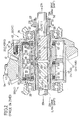
- a cylindrial differential casing 29 is composed of a casing body 31 and a cover 33, and rotatably supported by a differential gear carrier 39 via two bearings 35 and 37.
- a ring gear 41 is fixed to the differential casing 29 by bolts 43.
- a drive pinion gear is formed integral with a rear end of a drive pinion shaft 47 connected to a propeller shaft 9A and geared with the ring gear 41.
- the differential casing 29 is driven via the propeller shaft 9A from the engine 1A.
- a pair of first (left) and second (right) hub members 49 and 51 are arranged coaxially with each other.
- the hub members 49 and 51 are rotably supported by axle support portions 53 and 55 formed in the differential casing 29, and rotatably and coaxially fit together at 57 so as to provide mutual support for their free ends.
- An annular working chamber 59 is formed between the differential casing 29 and the hub members 49 and 51 and filled with a high viscosity silicone oil.
- two X-shaped (in cross section) sealing rings 61 and 63 and two backup rings 65 and 67 are arranged between the differential casing 29 and the hub members 49 and 51 at the two shaft support portions 53 and 55.
- an X-shaped sealing ring 69 and a backup ring 71 are arranged between the two hub members 49 and 51 at 57.
- the working chamber 59 is therefore sealed.
- the differential casing 29 is formed with a spline 73 and the hub members 49 and 51 are also formed with splines 75 and 77.
- a ring-shaped partition wall member (spacer) 79 is engaged with the spline 73 so as to surround the interfitting end portions of the two hub members 49 and 51. That is, the working chamber 59 is partitioned by this wall member 79.
- This partition wall member 79 is formed with a through hole 81 providing communication between the right and left sides of the working chamber 59.
- a plurality of outer plates 83 are engaged with the spline 73 on either side of the partition wall member 79 so as to be movable axially of the casing 29.
- a plurality of inner plates 85 are engaged with the splines 75 and 77 being arranged alternately with the outer plates 83 and are also movable axially of the casing 29.
- a spacer 87 is arranged between each two outer plates 83, and a spacer 89 is arranged between each two inner plates 85. These spacers serve to keep the plates spaced apart at an appropriate distance.
- the arrangment described provides a pair of viscous couplings 91 and 93.
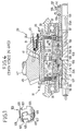
- two slidable clutch sleeves 99 and 101 are supported by two slide bearings 95 and 97 so as to be rotatable circumferentially and slidable axially.
- the clutch sleeves 99 and 101 are connected to each other via a coupling member 103.
- this coupling member 103 is a cylindrial member formed with three flexible arms 105 on each end thereof. Further, each arm 105 is formed with a claw 107 extending from an axially outward end of the arm 105 in the radially inward direction of the member 103.
- An outer circumferential groove 109 is formed at the adjacent ends of each sleeve 99 and 101.
- this coupling member 103 is fitted to the adjacent ends of the sleeves 99 and 101 by engaging the claws 107 of the arms 105 with the two circumferential grooves 109, the sleeves 99 and 101 are coupled so as to be rotatable relative to each other in the circumferential direction but slidable together in both axial directions.
- the first hub member 49 is formed with an inner spline 111 on the inner circumferential surface thereof;
- the second hub member 51 is formed with two inner splines 113 and 115 on the inner circumferential surface thereof;
- the differential casing 29 is formed with an inner spline 117 on the inner circumferential surface thereof.
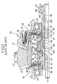
- the sleeve 99 is formed with an outer spline 119 engageable with the inner splines 111 and 113; and the sleeve 101 is formed with an outer spline 121 engageable with the inner splines 115 and 117.
- the clutch spline 121 is also disengaged.
- the clutch spline 121 is also engaged with the hub spline 115 as shown in Fig. 4.
- the clutch spline 121 is also engaged with the hub spline 115 and the casing spline 117, as shown in Fig. 5.
- first and second rear wheel drive shafts 21A and 23A are arranged coaxially and rotatably relative to each other.
- the lefthand drive shaft 21A is connected to the left rear wheel via a coupling device (not shown), and the righthand drive shaft 23A is connected to the right rear wheel via a coupling device (not shown).
- the drive shaft 21A is formed with an outer spline 127 on the outer circumferential surface thereof and the drive shaft 23A is formed with an outer spline 129 on the outer circumferential surface thereof.
- the sleeve 99 is formed with an inner spline 131 engageable with the outer spline 127 of the drive shaft 21A
- the sleeve 101 is formed with an inner spline 133 engageable with the outer spline 129 of the drive shaft 23A.
- the sleeves 99 and 101 are fitted to the drive shafts 21A and 23A so as to be slidable axially thereof.
- a ring 137 formed with an outer circumferential groove 135 is fitted to the sleeve 101 and located in position by two stopper rings 139 and 141.
- An arm of a shift fork (not shown) is engaged with the groove 135 in the ring 137, so that the shift fork may slide the sleeve 99 and, via the ring 137, the sleeve 101 axially.
- This shift fork is actuated manually by a driver or automatically according to vehicle steering conditions or road surface conditions.
- the differential revolution of the viscous coupling 91 or 93 decreases with decreasing drive resistance of the right and left rear wheels 27A and 25A, so that the rotation difference is decreasingly limited and therefore, the transmission torque also decreases.
- the power from the engine 1A can be differentially distributed to the right and left rear wheels 27A and 25A. Simultaneously, the rotational difference between the right and left rear wheels 27A and 25A and the rotational difference between the front wheels 17A and 19A and the rear wheels 25A and 27A can be controlled (limited or allowed). As shown in Fig.
- the power transmission apparatus of the present invention can transmit torque under control (restriction and permission) of the rotational difference and further can interrupt the torque transmission.
- torque is interrupted, it is possible to eliminate the loss due to the operation of the viscous couplings.
Landscapes
- Engineering & Computer Science (AREA)
- General Engineering & Computer Science (AREA)
- Mechanical Engineering (AREA)
- Chemical & Material Sciences (AREA)
- Combustion & Propulsion (AREA)
- Transportation (AREA)
- Arrangement And Driving Of Transmission Devices (AREA)
Claims (2)
Priority Applications (1)
| Application Number | Priority Date | Filing Date | Title |
|---|---|---|---|
| AT89104395T ATE76367T1 (de) | 1988-03-14 | 1989-03-13 | Leistungsuebertragungseinheit. |
Applications Claiming Priority (4)
| Application Number | Priority Date | Filing Date | Title |
|---|---|---|---|
| JP58235/88 | 1988-03-14 | ||
| JP5823588A JPH0626939B2 (ja) | 1988-03-14 | 1988-03-14 | 四輪駆動車の駆動力伝達・断続装置 |
| JP20326288A JPH0257730A (ja) | 1988-08-17 | 1988-08-17 | 動力伝達装置 |
| JP203262/88 | 1988-08-17 |
Publications (2)
| Publication Number | Publication Date |
|---|---|
| EP0333095A1 EP0333095A1 (de) | 1989-09-20 |
| EP0333095B1 true EP0333095B1 (de) | 1992-05-20 |
Family
ID=26399289
Family Applications (1)
| Application Number | Title | Priority Date | Filing Date |
|---|---|---|---|
| EP89104395A Expired - Lifetime EP0333095B1 (de) | 1988-03-14 | 1989-03-13 | Leistungsübertragungseinheit |
Country Status (4)
| Country | Link |
|---|---|
| US (1) | US4981192A (de) |
| EP (1) | EP0333095B1 (de) |
| AU (1) | AU614038B2 (de) |
| DE (1) | DE68901555D1 (de) |
Families Citing this family (12)
| Publication number | Priority date | Publication date | Assignee | Title |
|---|---|---|---|---|
| DE3924520A1 (de) * | 1989-07-25 | 1991-02-07 | Viscodrive Gmbh | Achsantrieb |
| DE4021747A1 (de) * | 1990-07-07 | 1992-01-16 | Gkn Automotive Ag | Antriebsanordnung |
| US5996720A (en) * | 1996-05-21 | 1999-12-07 | Dana Corporation | Dual disconnect drive assembly |
| US6517462B2 (en) | 2001-05-11 | 2003-02-11 | Spicer Technology, Inc. | Dual disconnect drive assembly |
| US7096990B2 (en) | 2001-07-30 | 2006-08-29 | Spicer Technology Inc. | Double disconnect assembly for multi-axle vehicles |
| US20030047402A1 (en) | 2001-09-13 | 2003-03-13 | Borgen Wayne Lee | Dual disconnect drive assembly |
| US6779420B2 (en) * | 2002-03-20 | 2004-08-24 | Gkn Automotive, Inc. | Integrated twin pull electronic torque management axle |
| JP4010839B2 (ja) * | 2002-03-25 | 2007-11-21 | 株式会社ショーワ | 動力切換装置 |
| JPWO2007083716A1 (ja) * | 2006-01-23 | 2009-06-11 | ビスコドライブジャパン株式会社 | ビスカスカップリング |
| US9643489B2 (en) * | 2013-03-10 | 2017-05-09 | Leonid Despotuli | System and method for controlling a vehicle |
| JP6112097B2 (ja) * | 2013-11-25 | 2017-04-12 | トヨタ自動車株式会社 | 4輪駆動車両のディスコネクト機構付左右駆動力配分ユニット |
| JP6822183B2 (ja) * | 2017-02-07 | 2021-01-27 | 株式会社ジェイテクト | 駆動力配分装置 |
Family Cites Families (7)
| Publication number | Priority date | Publication date | Assignee | Title |
|---|---|---|---|---|
| US4562897A (en) * | 1983-10-25 | 1986-01-07 | American Motors Corporation | Vehicle drivetrain including viscous clutch |
| AU572273B2 (en) * | 1984-08-27 | 1988-05-05 | Samuel Arthur Thomas Woodbridge | Transmission systems for vehicles |
| US4699237A (en) * | 1985-12-05 | 1987-10-13 | Fuji Jukogyo Kabushiki Kaisha | Four-wheel drive system for motor vehicles |
| EP0230962B1 (de) * | 1986-01-20 | 1991-01-09 | Honda Giken Kogyo Kabushiki Kaisha | Differentialeinrichtung mit Anwendung einer Flüssigkeit |
| FR2593873B1 (fr) * | 1986-01-24 | 1990-08-24 | Peugeot | Dispositif d'entrainement de deux arbres alignes, avec mecanisme differentiel, notamment deux arbres de transmission relies a deux roues arriere de vehicule |
| US4650028A (en) * | 1986-02-03 | 1987-03-17 | Chrysler Motors Corporation | Viscous coupling apparatus for on-demand four wheel drive system |
| US4728010A (en) * | 1986-07-22 | 1988-03-01 | Johnston Mack S | Keg tapper |
-
1989
- 1989-03-13 US US07/322,641 patent/US4981192A/en not_active Expired - Lifetime
- 1989-03-13 DE DE8989104395T patent/DE68901555D1/de not_active Expired - Lifetime
- 1989-03-13 EP EP89104395A patent/EP0333095B1/de not_active Expired - Lifetime
- 1989-03-14 AU AU31289/89A patent/AU614038B2/en not_active Ceased
Also Published As
| Publication number | Publication date |
|---|---|
| EP0333095A1 (de) | 1989-09-20 |
| AU3128989A (en) | 1989-09-14 |
| AU614038B2 (en) | 1991-08-15 |
| US4981192A (en) | 1991-01-01 |
| DE68901555D1 (de) | 1992-06-25 |
Similar Documents
| Publication | Publication Date | Title |
|---|---|---|
| US4982808A (en) | Viscous shear coupling | |
| EP0262434B1 (de) | Einrichtung zur Hemmung des Zwischenwellendifferentials für vierradgetriebene Fahrzeuge | |
| EP0315200B1 (de) | Kraftübertragungseinrichtung | |
| US4493387A (en) | Clutch driven front axle fourwheel drive system | |
| EP0379721B1 (de) | Differentialgetriebe | |
| US6620073B2 (en) | Driving force transmitting device for vehicle | |
| EP0333095B1 (de) | Leistungsübertragungseinheit | |
| GB2267322A (en) | Differential gearing unit | |
| CA1294560C (en) | Four wheel drive vehicle | |
| US4889206A (en) | Viscous shear coupling | |
| JPS61191434A (ja) | 車両の駆動装置 | |
| JPH0257730A (ja) | 動力伝達装置 | |
| JPS6390438A (ja) | 4輪駆動車用トランスフア | |
| JPH0322581Y2 (de) | ||
| JPH0626939B2 (ja) | 四輪駆動車の駆動力伝達・断続装置 | |
| JP2565890B2 (ja) | 動力伝達装置 | |
| GB2228979A (en) | Power transmission apparatus comprising assembly of differential and clutches for four wheel drive vehicle | |
| JPH0764220B2 (ja) | 4輪駆動車の駆動力伝達装置 | |
| JPH0341156Y2 (de) | ||
| JPH034833Y2 (de) | ||
| JPS63176723A (ja) | 4輪駆動車 | |
| JPH02146321A (ja) | ビスカスカップリング | |
| JPH0464730A (ja) | ビスカスカップリング | |
| JPS62286836A (ja) | 四輪駆動車の駆動装置 | |
| JPS62286835A (ja) | 四輪駆動車の駆動装置 |
Legal Events
| Date | Code | Title | Description |
|---|---|---|---|
| PUAI | Public reference made under article 153(3) epc to a published international application that has entered the european phase |
Free format text: ORIGINAL CODE: 0009012 |
|
| 17P | Request for examination filed |
Effective date: 19890313 |
|
| AK | Designated contracting states |
Kind code of ref document: A1 Designated state(s): AT DE FR GB IT |
|
| RAP1 | Party data changed (applicant data changed or rights of an application transferred) |
Owner name: VISCODRIVE JAPAN LTD |
|
| 17Q | First examination report despatched |
Effective date: 19901203 |
|
| GRAA | (expected) grant |
Free format text: ORIGINAL CODE: 0009210 |
|
| AK | Designated contracting states |
Kind code of ref document: B1 Designated state(s): AT DE FR GB IT |
|
| REF | Corresponds to: |
Ref document number: 76367 Country of ref document: AT Date of ref document: 19920615 Kind code of ref document: T |
|
| ITF | It: translation for a ep patent filed | ||
| REF | Corresponds to: |
Ref document number: 68901555 Country of ref document: DE Date of ref document: 19920625 |
|
| ET | Fr: translation filed | ||
| PLBE | No opposition filed within time limit |
Free format text: ORIGINAL CODE: 0009261 |
|
| STAA | Information on the status of an ep patent application or granted ep patent |
Free format text: STATUS: NO OPPOSITION FILED WITHIN TIME LIMIT |
|
| 26N | No opposition filed | ||
| PGFP | Annual fee paid to national office [announced via postgrant information from national office to epo] |
Ref country code: GB Payment date: 19990222 Year of fee payment: 11 |
|
| PGFP | Annual fee paid to national office [announced via postgrant information from national office to epo] |
Ref country code: FR Payment date: 19990318 Year of fee payment: 11 |
|
| PGFP | Annual fee paid to national office [announced via postgrant information from national office to epo] |
Ref country code: AT Payment date: 19990322 Year of fee payment: 11 |
|
| PGFP | Annual fee paid to national office [announced via postgrant information from national office to epo] |
Ref country code: DE Payment date: 19990521 Year of fee payment: 11 |
|
| PG25 | Lapsed in a contracting state [announced via postgrant information from national office to epo] |
Ref country code: GB Free format text: LAPSE BECAUSE OF NON-PAYMENT OF DUE FEES Effective date: 20000313 Ref country code: AT Free format text: LAPSE BECAUSE OF NON-PAYMENT OF DUE FEES Effective date: 20000313 |
|
| GBPC | Gb: european patent ceased through non-payment of renewal fee |
Effective date: 20000313 |
|
| PG25 | Lapsed in a contracting state [announced via postgrant information from national office to epo] |
Ref country code: FR Free format text: LAPSE BECAUSE OF NON-PAYMENT OF DUE FEES Effective date: 20001130 |
|
| REG | Reference to a national code |
Ref country code: FR Ref legal event code: ST |
|
| PG25 | Lapsed in a contracting state [announced via postgrant information from national office to epo] |
Ref country code: DE Free format text: LAPSE BECAUSE OF NON-PAYMENT OF DUE FEES Effective date: 20010103 |
|
| PG25 | Lapsed in a contracting state [announced via postgrant information from national office to epo] |
Ref country code: IT Free format text: LAPSE BECAUSE OF NON-PAYMENT OF DUE FEES;WARNING: LAPSES OF ITALIAN PATENTS WITH EFFECTIVE DATE BEFORE 2007 MAY HAVE OCCURRED AT ANY TIME BEFORE 2007. THE CORRECT EFFECTIVE DATE MAY BE DIFFERENT FROM THE ONE RECORDED. Effective date: 20050313 |