EP0331990B1 - Dispositif de transport de paquets de disques à diagramme - Google Patents
Dispositif de transport de paquets de disques à diagramme Download PDFInfo
- Publication number
- EP0331990B1 EP0331990B1 EP89103244A EP89103244A EP0331990B1 EP 0331990 B1 EP0331990 B1 EP 0331990B1 EP 89103244 A EP89103244 A EP 89103244A EP 89103244 A EP89103244 A EP 89103244A EP 0331990 B1 EP0331990 B1 EP 0331990B1
- Authority
- EP
- European Patent Office
- Prior art keywords
- belt
- bundle
- transporting
- transporting belt
- diagram
- Prior art date
- Legal status (The legal status is an assumption and is not a legal conclusion. Google has not performed a legal analysis and makes no representation as to the accuracy of the status listed.)
- Expired - Lifetime
Links
- 238000010586 diagram Methods 0.000 title description 62
- 230000037431 insertion Effects 0.000 claims 3
- 238000003780 insertion Methods 0.000 claims 3
- 230000008901 benefit Effects 0.000 description 3
- 238000009434 installation Methods 0.000 description 3
- 125000006850 spacer group Chemical group 0.000 description 3
- 230000004888 barrier function Effects 0.000 description 2
- 238000005452 bending Methods 0.000 description 2
- 239000000969 carrier Substances 0.000 description 2
- 239000011521 glass Substances 0.000 description 2
- 230000003442 weekly effect Effects 0.000 description 2
- 230000001154 acute effect Effects 0.000 description 1
- 230000005540 biological transmission Effects 0.000 description 1
- 238000010276 construction Methods 0.000 description 1
- 230000008878 coupling Effects 0.000 description 1
- 238000010168 coupling process Methods 0.000 description 1
- 238000005859 coupling reaction Methods 0.000 description 1
- -1 for example 25 or 26 Chemical group 0.000 description 1
- 230000006872 improvement Effects 0.000 description 1
- 238000000034 method Methods 0.000 description 1
- 230000035515 penetration Effects 0.000 description 1
- 230000008569 process Effects 0.000 description 1
- 229920002379 silicone rubber Polymers 0.000 description 1
- 239000004945 silicone rubber Substances 0.000 description 1
Images


Classifications
-
- G—PHYSICS
- G07—CHECKING-DEVICES
- G07C—TIME OR ATTENDANCE REGISTERS; REGISTERING OR INDICATING THE WORKING OF MACHINES; GENERATING RANDOM NUMBERS; VOTING OR LOTTERY APPARATUS; ARRANGEMENTS, SYSTEMS OR APPARATUS FOR CHECKING NOT PROVIDED FOR ELSEWHERE
- G07C5/00—Registering or indicating the working of vehicles
- G07C5/08—Registering or indicating performance data other than driving, working, idle, or waiting time, with or without registering driving, working, idle or waiting time
- G07C5/12—Registering or indicating performance data other than driving, working, idle, or waiting time, with or without registering driving, working, idle or waiting time in graphical form
Definitions
- the invention relates to an arrangement for transporting at least one chart to and from its registration position in a registration device, in which the chart can be entered through a slot and in which the input level determined by the position of the slot and the registration level in which the chart is during of registration.
- diagram slices combined into a bundle have the advantage of an uninterrupted registration over a longer period of time.
- tachographs for example, it is customary to use a bundle of diagram disks with seven diagram disks and thus to ensure weekly registration, i.e. the record carriers only have to be changed weekly, which means that the tachograph must be operated, which, as is well known, requires several operations and according to the working conditions in the cab Taking a trip is a chore that is often a chore, much easier.
- the transport of a diagram disk bundle from the input position determined by the position of the input slot to the registration position determined by the position of the centering and driving means then no particular technical difficulties if the two positions are essentially on the same level.
- the modern design trend in particular, requires relatively little installation space behind the front surface of the dashboard , for redirecting the recording medium to be entered from an input plane which intersects the front surface of the dashboard, into a centering and registration plane which is essentially parallel to the front surface of the dashboard.
- the object of the present invention was therefore to provide, in a recording device concept in which the recording media used are inserted through a slot in the recording device and automatically diverted into the registration position, with a transport device which is suitable for series devices and which ensures damage-free transport of more than allowed a chart.
- the solution to this problem provides that several diagram disks are combined to form a bundle of diagram disks, that individual diagram disks can be gradually separated from the bundle assembly in the registration process, that a strand of at least an endless, elastic transport belt can be carried between the input slot and the registration level to carry and deflect the bundle of diagram disks is provided, which is in geared connection with a motor, that a stationary deflection roller is provided, which is operatively connected to an outside of the entrained run of the conveyor belt, that the deflection roller and the conveyor belt-guiding belt rollers are arranged such that the smallest distance between one and the other run of the transport belt is smaller than the diameter of the belt rollers, and that the transport belt and the deflection roller are arranged such that a bundle of diagram disks entered through the input slot the wedge-shaped gap existing between the entrained strand of the transport belt and the deflection roller is fed.
- a preferred embodiment of the invention is characterized in that a pressure roller is provided which resiliently rests on a belt roller guiding the transport belt with the intermediate position of the transport belt, the line of contact between the pressure roller and the transport belt being in the registration plane.
- the advantage offered by the arrangement according to the invention can be seen in particular in that it basically makes it possible Transport the diagram disc bundle without damage and redirect it during transport.
- the one-part or multi-part, at least highly elastic and supple transport belt which is preferably made of silicone rubber, initially dodges at the start of the transport of a diagram disk bundle entered in the tachograph and only bends and bends the diagram disk bundle with increasing depth of penetration, ie with an increasingly effective lever arm thus deflected and at the same time entrained in the feed direction.
- the conveyor belt fits Bending behavior of the diagram disk bundle
- the conveyor belt or belts form a resilient or an elastic wall of the guide shaft between the input slot and the registration position, which allows the rigid diagram disk bundle to be deflected at a relatively short distance of approx. 40 mm at right angles.
- the transport belt provides the diagram disk bundle with a relatively large surface area, the pressure roller can therefore be effective with a relatively low contact pressure and thus the desired gentle transport is ensured with respect to the registration layer.
- the transport belt in particular in the preferred embodiment, on the one hand can adapt to the contour of an input diagram disc bundle, and on the other hand transverse forces caused by the diagram disc bundle not entered exactly in the center are not subtracted from the belt rollers that guide it. This risk is largely minimized, in particular in the preferred exemplary embodiment in which two transport belts arranged in parallel next to one another are used.
- the part of a dashboard or an instrument console 1 shown in FIGURE 1 has a first section 2 in which various operating elements 3 and a second section 4 in which display instruments are arranged.
- the speed display means of the tachograph 8 are designated 11 and 12, the time display means 13, 14 and 15.
- the adjustment shafts assigned to the working time adjustment buttons 19 and 20 are passed through the one aperture 17, while a recess 21 is provided in the other aperture 16, through which an input slot 22 for bundles of diagram disks serving as record carriers in the tachograph 8 - one, 23, is partially drawn in shown - is accessible.
- a button 24 which reaches through the panel 16 and can expediently be closed, for example an inner closure of the input slot 22 or an outward opening flap can be actuated.
- the recess 21 and the working time setting buttons 19 and 20 as well as the km counter, the display means of which could also be assigned to the dial of the tachograph 8, be interchanged so that the diagram disk bundle 23 would have to be entered from below, so to speak.
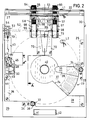
- FIGURE 2 shows, so to speak, the registration module of the tachograph 8, consisting of two angled plates 28 and 29 screwed together with spacers, for example 25 or 26, and spacers, one of which is designated 27, with a guide shaft between them 30 form, which is essentially limited on the end face by the strips and spacers and by guide rollers 31 and 32.
- the guide rollers 31 and 32 are rotatably mounted on suitable supports 33 and 34 connected to the plate 29 and engage through openings 35 and 36 in the plate 29 between the two plates 28 and 29, the one guide roller 32 guiding the guide shaft 30 in the transport direction limited and thus determines the centering position of the entered diagram disc bundle 23, of which the uppermost diagram disc is denoted by 37 in FIGURE 2 and the next following diagram disc which is visible through the sector-shaped cutout 38 of the diagram disc 37 is designated by 39.
- the bushing of the diagram disk bundle 23, via which the diagram disk bundle 23 is received on a centering mandrel, not shown, which can be raised and lowered perpendicularly to the registration plane, is designated by 40.
- the centering mandrel, the driving means and various wheels of the registration drive are mounted on an arm which in turn is pivotally mounted on an axis. Flaps 41 and 42 formed on the plate 29 serve as a holder for this axis.
- FIGURES 2, 3 and 4 are to be considered alternately below.
- a first gear branch of the gear train mounted in the gear housing 43 drives a transport roller 50, starting from a pinion 46 fastened on the shaft 45 of a motor 45, which is not designated, via the gear pairs 47 and 48 and the gear 49.
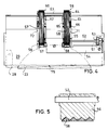
- the shaft 52 is mounted in a bearing bracket 54 assigned to the plate 29 and, according to the preferred embodiment shown, carries one first and a second belt roller 55 and 56, respectively.
- the two transport belts 57 and 58 are assigned two further belt rollers 59 and 60 as well as a deflection roller 61 and 62, respectively.
- the belt rollers 59 and 60 are fastened on a shaft 63 which is mounted in a bearing bridge 64 assigned to the plate 29, while the deflection roller pair 61, 62 is arranged on a shaft 65 which is associated with a bearing bridge 66 fastened to the plate 28.
- each transport belt 57, 58 is assigned a pressure roller 67 and 68, in such a way that the direction of force of a leaf spring 70 acting on a shaft 69 assigned to the pressure rollers is directed essentially radially with respect to the driving belt rollers 55 and 56.
- the transport belts 57 and 58 engage in the guide shaft 30 through suitable cutouts 71 and 72 in the plate 29 and the pressure rollers 67 and 68 through an opening 73 in the plate 28.
- the leaf spring 70 which is fastened on the plate 28, is preferably designed with two arms, and, as FIG. 3 shows, a bearing shell associated with the shaft 69 is molded onto the end of each arm.
- the motor 45 of the transport drive is switched off when one of the two light barriers L1, L2, namely L1 is no longer interrupted, ie the bundle of diagram disks protruding from the slot 22 has been removed from the tachograph 8 or, if it has not been removed, a certain time has elapsed . If the guide shaft is free, a new, ie unwritten diagram disk bundle 23 or also the one just taken for checking can be entered and pushed up to the support line between the transport belts 57, 58 and the deflection rollers 61, 62. In this case, the light barrier L1 is interrupted and the motor 45 of the transport drive is activated by pulling in a bundle of diagram disks 23.
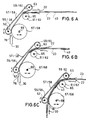
- FIG. 6A shows, the conveyor belts 57 and 58 elastically deflect due to the rigidity of the diagram disk bundle 23. It is only in the further course of the transport of the diagram disk bundle 23 that the belt tension increases and the belt tension increases Lever arm, that is to say increasing drawing depth, the diagram disk bundle 23 according to FIG. 6B is bent at the deflection rollers 61, 62 and is guided against the transfer gap 76 firmly assigned to the registration level between the transport belts 57 and 58 and the resilient pressure rollers 67 and 68. While the diagram disk bundle 23 is still in the transfer gap 76 (FIG.
- the diagram disk bundle stands still and a pulse generator assigned to the transport roller 50, consisting of a radially magnetized counter pressure roller 77 and a Hall sensor 78, then no longer delivers pulses. Switching off the transport drive and coupling the diagram disk bundle 23 to the registration drive can be controlled with this signal state.
- the diagram disk bundle must not be pulled off from the transfer nip 76 by means of the transport roller 50. It can also be effected by means of the appropriately conical centering mandrel, it being sufficient if contact with the transport belts or the pressure rollers is avoided during the registration movement of the diagram disk bundle.
- the invention can also be implemented in the simplest case by assigning a fixed deflection roller with the largest possible diameter to a single, relatively wide transport belt.
- FIGURE 7 shows in a simplified and thus impressive manner the problem on which the invention is based, namely having to deflect a relatively rigid recording medium (bundle of diagram disks) after a very short distance a at a relatively acute angle ⁇ from an input level into a registration level.
Landscapes
- Physics & Mathematics (AREA)
- General Physics & Mathematics (AREA)
- Time Recorders, Dirve Recorders, Access Control (AREA)
- Recording Measured Values (AREA)
- Navigation (AREA)
Claims (6)
- Dispositif pour le transport d'au moins un disque de diagramme (37, 39) dans sa position d'enregistrement et hors de cette position d'enregistrement dans un appareil enregistreur, dans lequel ledit disque de diagramme peut être introduit par une fente (22) et dans lequel le plan d'introduction déterminé par la position de ladite fente (22) se coupe avec le plan d'enregistrement dans lequel se trouve ledit disque de diagramme (37, 39) pendant le processus d'enregistrement,
caractérisé par le fait
que plusieurs disques de diagramme sont réunis en une liasse de disques de diagramme (23),
que des disques de diagramme individuels (37, 39) sont détachables l'un après l'autre de ladite liasse au cours des enregistrements,
que, pour l'entraînement et le renvoi de la liasse de disques de diagramme (23) entre la fente d'introduction (22) et le plan d'enregistrement, il est prévu un brin d'au moins une courroie élastique de transport sans fin (57) qui coopère fonctionnellement avec un moteur (45), qu'il est prévu une poulie de renvoi (61) à montage stationnaire qui coopère efficacement avec une face extérieure du brin d'entraînement de ladite courroie de transport (57),
que ladite poulie de renvoi (61) et des poulies de guidage (55, 59) de ladite courroie de transport (57) sont disposées de telle sorte que la plus petite distance entre l'un et l'autre des brins de ladite courroie de transport (57) soit plus petite que le diamètre des poulies de guidage (55, 59) et que ladite courroie de transport (57) et ladite poulie de renvoi (61) sont disposées de telle sorte qu'une liasse de disques de diagramme (23) introduite par la fente d'introduction (22) soit acheminée vers la fente cunéiforme existant entre le brin d'entraînement de ladite courroie de transport (57) et ladite poulie de renvoi (61). - Dispositif selon la revendication 1,
caractérisé par le fait
que la courroie de transport (57) présente, transversalement au sens de transport, un profil denté. - Dispositif selon la revendication 1,
caractérisé par le fait
que la courroie de transport (57) est constituée de plusieurs ganses. - Dispositif selon la revendication 1,
caractérisé par le fait
qu'il est prévu un galet presseur (68) qui s'appuie, avec intercalation de la courroie de transport, élastiquement sur une poulie de guidage (55) de ladite courroie de transport, la ligne de contact entre ledit galet presseur (68) et ladite courroie de transport (57) étant située dans le plan d'enregistrement. - Dispositif selon la revendication 4,
caractérisé par le fait
qu'à la courroie de transport (57) est associée au moins une poulie de transport (50) qui opère un acheminement d'une liasse de disques de diagramme (23) à l'intérieur du plan d'enregistrement. - Dispositif selon la revendication 1,
caractérisé par le fait
que deux courroies de transport (57 et 58) auxquelles est associé un entraînement commun (46, 51, 53, 52) sont disposées, à une distance qui est plus grande que le diamètre du coussinet (40) d'une liasse de disques de diagramme (23), en parallèle l'une à côté de l'autre.
Applications Claiming Priority (2)
| Application Number | Priority Date | Filing Date | Title |
|---|---|---|---|
| DE3807286A DE3807286A1 (de) | 1988-03-05 | 1988-03-05 | Anordnung zum transportieren eines diagrammscheibenbuendels |
| DE3807286 | 1988-03-05 |
Publications (3)
| Publication Number | Publication Date |
|---|---|
| EP0331990A2 EP0331990A2 (fr) | 1989-09-13 |
| EP0331990A3 EP0331990A3 (en) | 1990-06-27 |
| EP0331990B1 true EP0331990B1 (fr) | 1994-12-28 |
Family
ID=6348975
Family Applications (1)
| Application Number | Title | Priority Date | Filing Date |
|---|---|---|---|
| EP89103244A Expired - Lifetime EP0331990B1 (fr) | 1988-03-05 | 1989-02-24 | Dispositif de transport de paquets de disques à diagramme |
Country Status (8)
| Country | Link |
|---|---|
| US (1) | US4911420A (fr) |
| EP (1) | EP0331990B1 (fr) |
| JP (1) | JPH0682054B2 (fr) |
| AR (1) | AR244450A1 (fr) |
| BR (1) | BR8901042A (fr) |
| DE (2) | DE3807286A1 (fr) |
| RU (1) | RU2027148C1 (fr) |
| ZA (1) | ZA891621B (fr) |
Families Citing this family (3)
| Publication number | Priority date | Publication date | Assignee | Title |
|---|---|---|---|---|
| DE4039036A1 (de) * | 1990-12-07 | 1992-06-11 | Mannesmann Kienzle Gmbh | Vorrichtung zum transportieren von datentraegern |
| DE29701586U1 (de) * | 1997-01-31 | 1997-03-13 | VDO Adolf Schindling AG, 60326 Frankfurt | Anordnung zum Festspannen von Diagrammscheiben |
| DE20112945U1 (de) * | 2001-08-03 | 2001-10-04 | Siemens AG, 80333 München | Fahrtschreiber mit einem flachen, quaderförmigen Gehäuse und einer für die Verwendung von Diagrammscheibenbündeln vorgesehenen Registriereinrichtung |
Family Cites Families (9)
| Publication number | Priority date | Publication date | Assignee | Title |
|---|---|---|---|---|
| US2381719A (en) * | 1942-10-02 | 1945-08-07 | Harry W Brintnall | Sheet control delivery mechanism for lithograph, varnishing machines, and the like |
| US2703745A (en) * | 1952-02-11 | 1955-03-08 | Thomas K M Smith | Continuous chart recording |
| US3064261A (en) * | 1959-03-09 | 1962-11-13 | Orvel E Mullins | Automatic chart changer |
| US3046008A (en) * | 1960-04-05 | 1962-07-24 | Du Pont | Mechanism for stacking sheets |
| US3109694A (en) * | 1960-07-18 | 1963-11-05 | Mullins Mfg Company | Chart changers |
| US3684076A (en) * | 1970-02-02 | 1972-08-15 | Documentor Sciences Corp | Endless belt paper transporting and processing apparatus |
| DE2618439C2 (de) * | 1976-04-27 | 1978-06-01 | Nixdorf Computer Ag, 4790 Paderborn | Transporteinrichtung für die Auswertung von Identifizierungskarten |
| US4732375A (en) * | 1986-07-24 | 1988-03-22 | Cubic Western Data | Apparatus for handling strip-like media |
| DE3716486C1 (de) * | 1987-05-16 | 1988-01-07 | Mannesmann Kienzle Gmbh | Anordnung zum selbsttaetigen Positionieren einer Diagrammscheibe |
-
1988
- 1988-03-05 DE DE3807286A patent/DE3807286A1/de not_active Withdrawn
-
1989
- 1989-02-06 RU SU894613368A patent/RU2027148C1/ru active
- 1989-02-24 EP EP89103244A patent/EP0331990B1/fr not_active Expired - Lifetime
- 1989-02-24 DE DE58908811T patent/DE58908811D1/de not_active Expired - Fee Related
- 1989-02-28 US US07/316,869 patent/US4911420A/en not_active Expired - Fee Related
- 1989-03-02 ZA ZA891621A patent/ZA891621B/xx unknown
- 1989-03-06 BR BR898901042A patent/BR8901042A/pt unknown
- 1989-03-06 JP JP1052171A patent/JPH0682054B2/ja not_active Expired - Fee Related
- 1989-03-06 AR AR89313335A patent/AR244450A1/es active
Also Published As
| Publication number | Publication date |
|---|---|
| ZA891621B (en) | 1989-12-27 |
| EP0331990A2 (fr) | 1989-09-13 |
| JPH01274013A (ja) | 1989-11-01 |
| JPH0682054B2 (ja) | 1994-10-19 |
| US4911420A (en) | 1990-03-27 |
| AR244450A1 (es) | 1993-10-29 |
| BR8901042A (pt) | 1989-10-24 |
| RU2027148C1 (ru) | 1995-01-20 |
| DE3807286A1 (de) | 1989-09-14 |
| DE58908811D1 (de) | 1995-02-09 |
| EP0331990A3 (en) | 1990-06-27 |
Similar Documents
| Publication | Publication Date | Title |
|---|---|---|
| DE3331211C2 (fr) | ||
| DE3506748A1 (de) | Kassetten-ladevorrichtung fuer ein video-kassettengeraet | |
| EP0266629A2 (fr) | Appareil pour effectuer l'ouverture automatique et le mélange de balles de fibres | |
| DE3337689A1 (de) | Scheibeneinheit | |
| DE102011107047B4 (de) | Rückensteifer Kettenantrieb mit gleichmäßigem, stoßfreiem Kettenlauf | |
| DE3685868T2 (de) | Kassettenlademechanismus eines magnetischen aufnahme-/wiedergabegeraetes. | |
| DE69109908T2 (de) | Vorrichtung für Dokumententransport. | |
| EP0331990B1 (fr) | Dispositif de transport de paquets de disques à diagramme | |
| DE19860765A1 (de) | Gehäuse, insbesondere für eine Verpackungsmaschine | |
| EP0864137B1 (fr) | Enregistreur de marche avec tiroir | |
| DE3716486C1 (de) | Anordnung zum selbsttaetigen Positionieren einer Diagrammscheibe | |
| DE19609145A1 (de) | Einrichtung zum automatischen und/oder manuellen Werkzeugwechsel | |
| EP1017013B1 (fr) | Dispositif de verrouillage pour un appareil de lecture/écriture de cartes de données | |
| DE69321251T2 (de) | Motorgetriebe | |
| DE2149442B2 (de) | Spieldosenwerk | |
| DE3615643C1 (de) | Anordnung zum Transportieren einer Diagrammscheibe | |
| WO1996030888A1 (fr) | Dispositif de presentation de supports publicitaires eclaires par l'arriere | |
| EP0330002B1 (fr) | Dispositif de positionnement horaire exact et automatique d'un paquet de disques à diagramme pour l'enregistrement par sections mais continu | |
| DE3642270C2 (fr) | ||
| DE4128088C2 (de) | Automatische Zeichenmaschine mit Papierdurchzug | |
| EP0800151A2 (fr) | Liaison d'entraînement pour un dispositif d'enregistrement de tachygraphe | |
| DE19507362C1 (de) | Teigwickelmaschine mit mindestens einer austauschbaren Walze | |
| EP0368219A2 (fr) | Enregistreur de route avec des moyens d'entraînement actionnés en temps pour des portes-diagrammes servant comme support d'enregistrement | |
| DE102024124114A1 (de) | Kraftfahrzeug-Türantrieb | |
| DE19756712B4 (de) | Mittel zum Festhalten eines dem Festspannen von Diagrammscheiben in einem Fahrtschreiber dienenden Spannelementes in einer Mitnahmeposition |
Legal Events
| Date | Code | Title | Description |
|---|---|---|---|
| PUAI | Public reference made under article 153(3) epc to a published international application that has entered the european phase |
Free format text: ORIGINAL CODE: 0009012 |
|
| AK | Designated contracting states |
Kind code of ref document: A2 Designated state(s): CH DE ES FR GB IT LI SE |
|
| PUAL | Search report despatched |
Free format text: ORIGINAL CODE: 0009013 |
|
| AK | Designated contracting states |
Kind code of ref document: A3 Designated state(s): CH DE ES FR GB IT LI SE |
|
| 17P | Request for examination filed |
Effective date: 19901210 |
|
| 17Q | First examination report despatched |
Effective date: 19920724 |
|
| RAP1 | Party data changed (applicant data changed or rights of an application transferred) |
Owner name: MANNESMANN KIENZLE GMBH |
|
| GRAA | (expected) grant |
Free format text: ORIGINAL CODE: 0009210 |
|
| AK | Designated contracting states |
Kind code of ref document: B1 Designated state(s): CH DE ES FR GB IT LI SE |
|
| PG25 | Lapsed in a contracting state [announced via postgrant information from national office to epo] |
Ref country code: IT Free format text: LAPSE BECAUSE OF FAILURE TO SUBMIT A TRANSLATION OF THE DESCRIPTION OR TO PAY THE FEE WITHIN THE PRE;WARNING: LAPSES OF ITALIAN PATENTS WITH EFFECTIVE DATE BEFORE 2007 MAY HAVE OCCURRED AT ANY TIME BEFORE 2007. THE CORRECT EFFECTIVE DATE MAY BE DIFFERENT FROM THE ONE RECORDED.SCRIBED TIME-LIMIT Effective date: 19941228 Ref country code: ES Free format text: THE PATENT HAS BEEN ANNULLED BY A DECISION OF A NATIONAL AUTHORITY Effective date: 19941228 |
|
| REF | Corresponds to: |
Ref document number: 58908811 Country of ref document: DE Date of ref document: 19950209 |
|
| PG25 | Lapsed in a contracting state [announced via postgrant information from national office to epo] |
Ref country code: CH Effective date: 19950228 Ref country code: LI Effective date: 19950228 |
|
| ET | Fr: translation filed | ||
| PG25 | Lapsed in a contracting state [announced via postgrant information from national office to epo] |
Ref country code: SE Effective date: 19950328 |
|
| GBT | Gb: translation of ep patent filed (gb section 77(6)(a)/1977) |
Effective date: 19950301 |
|
| PLBE | No opposition filed within time limit |
Free format text: ORIGINAL CODE: 0009261 |
|
| STAA | Information on the status of an ep patent application or granted ep patent |
Free format text: STATUS: NO OPPOSITION FILED WITHIN TIME LIMIT |
|
| 26N | No opposition filed | ||
| PGFP | Annual fee paid to national office [announced via postgrant information from national office to epo] |
Ref country code: GB Payment date: 19970113 Year of fee payment: 9 |
|
| PGFP | Annual fee paid to national office [announced via postgrant information from national office to epo] |
Ref country code: FR Payment date: 19970114 Year of fee payment: 9 |
|
| PG25 | Lapsed in a contracting state [announced via postgrant information from national office to epo] |
Ref country code: GB Free format text: LAPSE BECAUSE OF NON-PAYMENT OF DUE FEES Effective date: 19980224 |
|
| PG25 | Lapsed in a contracting state [announced via postgrant information from national office to epo] |
Ref country code: FR Free format text: THE PATENT HAS BEEN ANNULLED BY A DECISION OF A NATIONAL AUTHORITY Effective date: 19980228 |
|
| GBPC | Gb: european patent ceased through non-payment of renewal fee |
Effective date: 19980224 |
|
| REG | Reference to a national code |
Ref country code: FR Ref legal event code: ST |
|
| PGFP | Annual fee paid to national office [announced via postgrant information from national office to epo] |
Ref country code: DE Payment date: 20020422 Year of fee payment: 14 |
|
| PG25 | Lapsed in a contracting state [announced via postgrant information from national office to epo] |
Ref country code: DE Free format text: LAPSE BECAUSE OF NON-PAYMENT OF DUE FEES Effective date: 20030902 |