EP0330056A2 - Servicewagen - Google Patents
Servicewagen Download PDFInfo
- Publication number
- EP0330056A2 EP0330056A2 EP89102535A EP89102535A EP0330056A2 EP 0330056 A2 EP0330056 A2 EP 0330056A2 EP 89102535 A EP89102535 A EP 89102535A EP 89102535 A EP89102535 A EP 89102535A EP 0330056 A2 EP0330056 A2 EP 0330056A2
- Authority
- EP
- European Patent Office
- Prior art keywords
- hinge
- door leaf
- pivot axes
- hand
- bearings
- Prior art date
- Legal status (The legal status is an assumption and is not a legal conclusion. Google has not performed a legal analysis and makes no representation as to the accuracy of the status listed.)
- Granted
Links
- 230000001681 protective effect Effects 0.000 description 1
Images


Classifications
-
- E—FIXED CONSTRUCTIONS
- E05—LOCKS; KEYS; WINDOW OR DOOR FITTINGS; SAFES
- E05D—HINGES OR SUSPENSION DEVICES FOR DOORS, WINDOWS OR WINGS
- E05D3/00—Hinges with pins
- E05D3/06—Hinges with pins with two or more pins
- E05D3/12—Hinges with pins with two or more pins with two parallel pins and one arm
-
- A—HUMAN NECESSITIES
- A47—FURNITURE; DOMESTIC ARTICLES OR APPLIANCES; COFFEE MILLS; SPICE MILLS; SUCTION CLEANERS IN GENERAL
- A47B—TABLES; DESKS; OFFICE FURNITURE; CABINETS; DRAWERS; GENERAL DETAILS OF FURNITURE
- A47B31/00—Service or tea tables, trolleys, or wagons
-
- A—HUMAN NECESSITIES
- A47—FURNITURE; DOMESTIC ARTICLES OR APPLIANCES; COFFEE MILLS; SPICE MILLS; SUCTION CLEANERS IN GENERAL
- A47B—TABLES; DESKS; OFFICE FURNITURE; CABINETS; DRAWERS; GENERAL DETAILS OF FURNITURE
- A47B31/00—Service or tea tables, trolleys, or wagons
- A47B2031/002—Catering trolleys
-
- A—HUMAN NECESSITIES
- A47—FURNITURE; DOMESTIC ARTICLES OR APPLIANCES; COFFEE MILLS; SPICE MILLS; SUCTION CLEANERS IN GENERAL
- A47B—TABLES; DESKS; OFFICE FURNITURE; CABINETS; DRAWERS; GENERAL DETAILS OF FURNITURE
- A47B2220/00—General furniture construction, e.g. fittings
- A47B2220/0061—Accessories
- A47B2220/0069—Hinges
- A47B2220/0072—Hinges for furniture
-
- B—PERFORMING OPERATIONS; TRANSPORTING
- B62—LAND VEHICLES FOR TRAVELLING OTHERWISE THAN ON RAILS
- B62B—HAND-PROPELLED VEHICLES, e.g. HAND CARTS OR PERAMBULATORS; SLEDGES
- B62B2202/00—Indexing codes relating to type or characteristics of transported articles
- B62B2202/67—Service trolleys, e.g. in aircraft
-
- E—FIXED CONSTRUCTIONS
- E05—LOCKS; KEYS; WINDOW OR DOOR FITTINGS; SAFES
- E05Y—INDEXING SCHEME ASSOCIATED WITH SUBCLASSES E05D AND E05F, RELATING TO CONSTRUCTION ELEMENTS, ELECTRIC CONTROL, POWER SUPPLY, POWER SIGNAL OR TRANSMISSION, USER INTERFACES, MOUNTING OR COUPLING, DETAILS, ACCESSORIES, AUXILIARY OPERATIONS NOT OTHERWISE PROVIDED FOR, APPLICATION THEREOF
- E05Y2900/00—Application of doors, windows, wings or fittings thereof
- E05Y2900/20—Application of doors, windows, wings or fittings thereof for furniture, e.g. cabinets
-
- E—FIXED CONSTRUCTIONS
- E05—LOCKS; KEYS; WINDOW OR DOOR FITTINGS; SAFES
- E05Y—INDEXING SCHEME ASSOCIATED WITH SUBCLASSES E05D AND E05F, RELATING TO CONSTRUCTION ELEMENTS, ELECTRIC CONTROL, POWER SUPPLY, POWER SIGNAL OR TRANSMISSION, USER INTERFACES, MOUNTING OR COUPLING, DETAILS, ACCESSORIES, AUXILIARY OPERATIONS NOT OTHERWISE PROVIDED FOR, APPLICATION THEREOF
- E05Y2900/00—Application of doors, windows, wings or fittings thereof
- E05Y2900/50—Application of doors, windows, wings or fittings thereof for vehicles
- E05Y2900/53—Type of wing
- E05Y2900/531—Doors
Definitions
- the present invention relates to a service car according to the preamble of claim 1.
- the door leaf is attached to the body using a piano hinge.
- This hinge connection has the advantage that in the narrow aisles between the rows of seats of a passenger aircraft the door leaf can be swiveled around 270 ° and flat against the outer wall of the body. Another advantage is that the door leaf can be swiveled easily and, despite the hinge play required for this, does not hang in the hinge and twists in it.
- the pivot axis which forms one of the four vertical edges of the body and is therefore easily vulnerable, has to be replaced frequently and with considerable effort.
- the object of the present invention is to improve a service vehicle of the type mentioned in such a way that the aforementioned disadvantages are eliminated while maintaining the advantages mentioned.
- the door leaf 2 is hinged to the left on the body-side door frame and can be opened in the direction of the arrow shown.
- the hinge connection between the body 1 on the one hand and the door leaf 2 on the other hand is described below with reference to FIGS. 2 to 6.
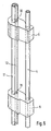
- the front end of the body is designed as a door frame in whose frame wall following the side wall 2 is mounted in corresponding bearings a pivot axis 4 with a circular cross section, which extends approximately over the entire height of the body 1 and after removal of the protective cap 5 from above vertically in the cabinet-side bearing is pluggable.
- a pivot axis 4 with a circular cross section, which extends approximately over the entire height of the body 1 and after removal of the protective cap 5 from above vertically in the cabinet-side bearing is pluggable.
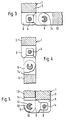
- In the frame leg following the side wall 3 there are recesses 6 at regular intervals, in which the corresponding sections of the pivot axis 4 are accessible from all sides.
- Hinge bodies 5 are articulated to these sections of the pivot axis 4 and are provided with a bore 8 through which the pivot axis 4 is also inserted.
- each bearing body 5 is thus pivotable about the pivot axis 4, which in turn is pivotable about its longitudinal axis is stored in the cabinet-side bearings.
- each bearing body has a second parallel bore 9, into which a nose 10 made in one piece with the hinge body projects.
- a second pivot axis 11 is inserted through the bores 9 of the hinge body 5 and is provided with an axially parallel groove 12 which corresponds in cross section to the nose 10. The pivot axis 11 is thereby non-rotatable with respect to the hinge body 5 in which it can be displaced longitudinally.
- the second pivot axis 11 is mounted between the hinge bodies 5 in corresponding, axially aligned bores in the door leaf 13, which has recesses 14 in the area of the hinge body 5 and can therefore be pivoted about the pivot axis 11 or around the hinge body 5.
- Fig. 3 shows the service car with the door closed. In this state, the hinge is distanced from the outermost vertical edge of the body 1 and is therefore protected against impacts.
- Fig. 4 shows the service car with the door pivoted forward, the hinge between the body 1 and the door leaf 2 is protected. If the door leaf 2 is folded outwards and abuts against the side wall 3, the door leaf 2 forms a rounded, vertical and therefore less sensitive edge, against which the hinge body 5 is also set back.
- the hinge play can be chosen to be so great that the door leaf is easily pivotable without hanging in the hinge or twisting in it.
- the torsion-proof connection between the hinge bodies 5 on the one hand and the pivot axis 11 on the other hand is shown and described in the described embodiment, the torsion-proof connection can also be between the wall 3 and the pivot axis 4 or between the pivot axis 4 and the hinge body 5 or between the door leaf 3 and the pivot axis 11 may be attached. It is also possible to mount the pivot axes 4 and 11 in a rotationally fixed manner in the wall 3 or in the door leaf 3 and to provide the pivot connection between the hinge bodies 5 and the pivot axes 4 and 11.
Landscapes
- Engineering & Computer Science (AREA)
- Mechanical Engineering (AREA)
- Hinges (AREA)
- Superconductors And Manufacturing Methods Therefor (AREA)
- Threshing Machine Elements (AREA)
- Gear-Shifting Mechanisms (AREA)
- Handcart (AREA)
- Acyclic And Carbocyclic Compounds In Medicinal Compositions (AREA)
- Pyrane Compounds (AREA)
- Liquid Crystal Substances (AREA)
Abstract
Description
- Die vorliegende Erfindung bezieht sich auf einen Servicewagen gemäss dem Oberbegriff des Anspruchs 1.
- Bei einem Servicewagen dieser Art ist das Türblatt mittels eines Klavierbandes am Korpus angeschlagen. Diese Scharnierverbindung hat den Vorteil, dass in den engen Gängen zwischen den Sitzreihen eines Passagierflugzeugs das Türblatt um 270° herum und flach an die Aussenwand des Korpus geschwenkt werden kann. Ein weiterer Vorteil ist, dass das Türblatt leicht schwenkbar ist und trotz dem dafür erforderlichen Scharnierspiel nicht im Scharnier hängt und sich darin verwindet. Es hat indessen den Nachteil, dass die Schwenkachse, die eine der vier vertikalen Kanten des Korpus bildet und daher leicht verletzlich ist, häufig und mit beachtlichem Arbeitsaufwand ersetzt werden muss.
- Die vorliegende Erfindung stellt sich die Aufgabe, einen Servicewagen der erwähnten Art derart zu verbessern, dass unter Wahrung der genannten Vorteile die erwähnten Nachteile entfallen.
- Anhand der beiliegenden schematischen Zeichnung wird die Erfindung beispielsweise erläutert. Es zeigen:
- Fig. 1 einen Servicewagen in perspektivischer Ansicht,
- Fig. 2 eine Vorderansicht des Servicewagens bei geöffneter Türe,
- Fig. 3 bis 5 einen Schnitt längs der Linie III-III in Fig. 2, wobei das Türblatt in drei verschiedenen Stellungen gezeigt ist und
- Fig. 6 einen Teil des Scharniers in perspektivischer Darstellung.
- Der Servicewagen nach Fig. 1 weist einen auf feststellbaren Rädern verfahrbaren Korpus 1 auf, der an seiner Frontseite durch sein Türblatt 2 verschlossen ist. Das Türblatt 2 ist links am korpusseitigen Türrahmen angeschlagen und in Richtung des eingezeichneten Pfeiles aufklappbar. Die Scharnierverbindung zwischen dem Korpus 1 einerseits und dem Türblatt 2 anderseits wird nachfolgend mit Bezug auf die Fig. 2 bis 6 beschrieben.
- Das vordere Ende des Korpus ist als Türrahmen gestaltet in dessen der Seitenwand 2 folgenden Rahmenschenkel in entsprechenden Lagern eine im Querschnitt kreisrunde Schwenkachse 4 gelagert ist, welche sich näherungsweise über die ganze Höhe des Korpus 1 erstreckt und nach einem Entfernen der Schutzkappe 5 von oben senkrecht in die korpusseitigen Lager steckbar ist. Im der Seitenwand 3 folgenden Rahmenschenkel sind in regelmässigem Abstand Ausnehmungen 6 vorhanden, in welchen die entsprechenden Abschnitte der Schwenkachse 4 allseits zugänglich sind. An diesen Abschnitten der Schwenkachse 4 sind Scharnierkörper 5 angelenkt, welche mit einer Bohrung 8 versehen sind durch welche die Schwenkachse 4 ebenfalls hindurch gesteckt ist. Der Scharnierkörper 5 ist somit um die Schwenkachse 4 verschwenkbar, welche ihrerseits um ihre Längsachse schwenkbar in den korpusseitigen Lagern gelagert ist. Mit Abstand zur Bohrung 8 weist jeder Lagerkörper eine zweite parallele Bohrung 9 auf, in die eine mit dem Scharnierkörper einstückig gefertigte Nase 10 ragt. Durch die Bohrungen 9 der Scharnierkörper 5 ist eine zweite Schwenkachse 11 gesteckt, welche mit einer achsparallelen, im Querschnitt der Nase 10 entsprechenden Nut 12 versehen ist. Die Schwenkachse 11 ist dadurch verdrehfest mit Bezug auf die Scharnierkörper 5 in denen sie längsachsial verschiebbar ist. Die zweite Schwenkachse 11 ist zwischen den Scharnierkörpern 5 in entsprechenden, achsial ausgerichteten Bohrungen im Türblatt 13 gelagert, welches im Bereich der Scharnierkörper 5 mit Ausnehmungen 14 versehen und daher um die Schwenkachse 11 bzw. um die Scharnierkörper 5 herum geschwenkt werden kann.
- Fig. 3 zeigt den Servicewagen bei geschlossener Türe. In diesem Zustand ist das Scharnier von der äussersten vertikalen Kante des Korpus 1 distanziert und daher gegen Schläge geschützt. Fig. 4 zeigt den Servicewagen mit nach vorne geschwenkter Türe, wobei das Scharnier zwischen Korpus 1 und Türblatt 2 geschützt ist. Ist das Türblatt 2 nach aussen zurückgeklappt und gegen die Seitenwand 3 anliegend, bildet das Türblatt 2 eine gerundete, vertikale und daher weniger schlagempflindliche Kante, gegenüber der die Scharnierkörper 5 zudem zurückversetzt sind.
- Dadurch, dass zwischen den Scharnierkörpern 5 und den Schwenkachsen 4, 11 einerseits oder dem Türblatt 13 bzw. dem Korpus 1 anderseits eine verdrehfeste Verbindung besteht, kann das Scharnierspiel so gross gewählt werden, dass das Türblatt leicht verschwenkbar ist ohne aber im Scharnier zu hängen oder sich darin zu verwinden.
- Obwohl beim beschriebenen Ausführungsbeispiel die verdrehfeste Verbindung zwischen den Scharnierkörpern 5 einerseits und der Schwenkachse 11 anderseits gezeigt und beschrieben ist, kann die drehfeste Verbindung auch zwischen der Wand 3 und der Schwenkachse 4 oder zwischen der Schwenkachse 4 und dem Scharnierkörper 5 oder zwischen dem Türblatt 3 und der Schwenkachse 11 angebracht sein. Es besteht auch die Möglichkeit, die Schwenkachsen 4 und 11 verdrehfest in der Wand 3 bzw. im Türblatt 3 zu lagern und die Schwenkverbindung zwischen den Scharnierkörpern 5 und den Schwenkachsen 4 und 11 vorzusehen.
Claims (4)
Priority Applications (1)
| Application Number | Priority Date | Filing Date | Title |
|---|---|---|---|
| AT89102535T ATE75111T1 (de) | 1988-02-26 | 1989-02-15 | Servicewagen. |
Applications Claiming Priority (2)
| Application Number | Priority Date | Filing Date | Title |
|---|---|---|---|
| CH721/88 | 1988-02-26 | ||
| CH721/88A CH675058A5 (de) | 1988-02-26 | 1988-02-26 |
Publications (3)
| Publication Number | Publication Date |
|---|---|
| EP0330056A2 true EP0330056A2 (de) | 1989-08-30 |
| EP0330056A3 EP0330056A3 (en) | 1989-12-20 |
| EP0330056B1 EP0330056B1 (de) | 1992-04-22 |
Family
ID=4193637
Family Applications (1)
| Application Number | Title | Priority Date | Filing Date |
|---|---|---|---|
| EP89102535A Expired - Lifetime EP0330056B1 (de) | 1988-02-26 | 1989-02-15 | Servicewagen |
Country Status (6)
| Country | Link |
|---|---|
| US (1) | US5056194A (de) |
| EP (1) | EP0330056B1 (de) |
| JP (1) | JPH01280410A (de) |
| AT (1) | ATE75111T1 (de) |
| CH (1) | CH675058A5 (de) |
| DE (1) | DE58901206D1 (de) |
Cited By (4)
| Publication number | Priority date | Publication date | Assignee | Title |
|---|---|---|---|---|
| FR2699587A1 (fr) * | 1992-12-22 | 1994-06-24 | Olivo | Charnière à double articulation pour porte de conteneur. |
| EP0801197A1 (de) * | 1996-04-09 | 1997-10-15 | MONETTI S.p.A. | Isothermischer Behälter mit doppelgelenkiger Tür |
| NL1035220C2 (nl) * | 2008-03-28 | 2009-09-29 | Aerocat B V | Trolley. |
| EP3051047A1 (de) * | 2015-02-02 | 2016-08-03 | Zodiac Aircatering Equipment Europe B.V. | Scharnieranordnung für bordküchenbehälter |
Families Citing this family (8)
| Publication number | Priority date | Publication date | Assignee | Title |
|---|---|---|---|---|
| DE20218538U1 (de) | 2002-11-29 | 2003-02-27 | GEBHARDT Transport- und Lagersysteme GmbH, 93413 Cham | Schwenkvorrichtung |
| US20060225250A1 (en) * | 2005-04-06 | 2006-10-12 | Noubar Yeremlan | Hinge system for storm door |
| US8465030B2 (en) | 2008-12-07 | 2013-06-18 | Norduyn Inc. | Modular utility cart |
| GB2480370B (en) | 2010-05-14 | 2017-03-29 | Norduyn Inc | Body reinforcement and method of manufacturing thereof |
| JP2014030184A (ja) * | 2012-07-06 | 2014-02-13 | Panasonic Corp | 通信装置及び無線通信システム |
| US8936260B2 (en) * | 2012-07-20 | 2015-01-20 | B/E Aerospace, Inc. | Meal cart for an aircraft galley |
| EP3038915B1 (de) | 2013-08-30 | 2019-12-11 | B/E Aerospace, Inc. | Mobiler bordküchenwagen |
| GB2521812B (en) * | 2013-11-04 | 2016-11-02 | Weight Reduction And Aerospace Security Products Ltd | Portable container system |
Family Cites Families (8)
| Publication number | Priority date | Publication date | Assignee | Title |
|---|---|---|---|---|
| US378861A (en) * | 1888-03-06 | Hinge | ||
| US730876A (en) * | 1903-03-03 | 1903-06-16 | Stanley Works | Hinge. |
| US2494682A (en) * | 1945-09-28 | 1950-01-17 | American Bantam Car Company | Door hinge |
| US2561206A (en) * | 1949-04-01 | 1951-07-17 | Kaspar Rudolf | Wood screen with lock joints |
| GB825285A (en) * | 1955-09-23 | 1959-12-16 | John Lloyd Wilson | Improved hinge |
| FR2228353A5 (en) * | 1973-05-02 | 1974-11-29 | Uta Union Transports Aeriens | Trolley for use on aircraft - has demountable light alloy parts with plastics insulation |
| EP0067122B1 (de) * | 1981-06-04 | 1986-03-05 | Schweizerische Aluminium Ag | Vorrichtung zum Anlenken eines Schwenkflügels an ein angrenzendes Bauteil |
| US4610560A (en) * | 1984-02-22 | 1986-09-09 | Channel-Kor Systems Inc. | Panel display connector |
-
1988
- 1988-02-26 CH CH721/88A patent/CH675058A5/de not_active IP Right Cessation
-
1989
- 1989-02-15 DE DE8989102535T patent/DE58901206D1/de not_active Expired - Fee Related
- 1989-02-15 EP EP89102535A patent/EP0330056B1/de not_active Expired - Lifetime
- 1989-02-15 AT AT89102535T patent/ATE75111T1/de not_active IP Right Cessation
- 1989-02-27 JP JP1046329A patent/JPH01280410A/ja active Pending
- 1989-02-27 US US07/316,222 patent/US5056194A/en not_active Expired - Fee Related
Cited By (6)
| Publication number | Priority date | Publication date | Assignee | Title |
|---|---|---|---|---|
| FR2699587A1 (fr) * | 1992-12-22 | 1994-06-24 | Olivo | Charnière à double articulation pour porte de conteneur. |
| EP0801197A1 (de) * | 1996-04-09 | 1997-10-15 | MONETTI S.p.A. | Isothermischer Behälter mit doppelgelenkiger Tür |
| NL1035220C2 (nl) * | 2008-03-28 | 2009-09-29 | Aerocat B V | Trolley. |
| WO2009120067A3 (en) * | 2008-03-28 | 2010-07-29 | Aerocat B.V. | Trolley |
| EP3051047A1 (de) * | 2015-02-02 | 2016-08-03 | Zodiac Aircatering Equipment Europe B.V. | Scharnieranordnung für bordküchenbehälter |
| NL2014218B1 (en) * | 2015-02-02 | 2016-10-12 | Zodiac Aircatering Equipment Europe B V | Hinge construction for galley container. |
Also Published As
| Publication number | Publication date |
|---|---|
| DE58901206D1 (de) | 1992-05-27 |
| EP0330056B1 (de) | 1992-04-22 |
| US5056194A (en) | 1991-10-15 |
| CH675058A5 (de) | 1990-08-31 |
| JPH01280410A (ja) | 1989-11-10 |
| ATE75111T1 (de) | 1992-05-15 |
| EP0330056A3 (en) | 1989-12-20 |
Similar Documents
| Publication | Publication Date | Title |
|---|---|---|
| DE2039103A1 (de) | Sicherheitsgurteinrichtung | |
| EP0330056B1 (de) | Servicewagen | |
| EP0664987B1 (de) | Vorrichtung zur Schwenkbewegung einer Scheibe, insbesondere an Kühl- oder Verkaufstheken | |
| DE3719974A1 (de) | Dachgepaecktraegersystem | |
| AT1969U1 (de) | Wandstütze für fassadenunterkonstruktionen | |
| DE1584080A1 (de) | Aufhaengung fuer Schwingtueren | |
| DE4312405A1 (de) | Mittelpufferkupplung fuer schienenfahrzeuge mit einer schutzvorrichtung | |
| DE19922512C1 (de) | Rückwand für ein Lastfahrzeug | |
| DE3825285A1 (de) | Falttuer mit mehreren fluegelpaaren | |
| DE69410656T2 (de) | Wiegegerät, hauptsächlich zur Montage auf einem Fahrzeug | |
| DE3723706C2 (de) | Ladewagen | |
| DE3707447A1 (de) | Gepaecktraeger fuer einen personenkraftwagen | |
| DE8913185U1 (de) | Fahrerkabine für einen Traktor mit umkehrbarer Sitzposition | |
| DE3812708C2 (de) | Transportfahrzeug für Glasscheibenpakete | |
| DE29717998U1 (de) | Kabinenaufhängung | |
| DE2442473C2 (de) | Zargenunterband für Holz- oder Kunststoffzargen für rechts- oder linksanschlagbare Normtüren | |
| DE7429630U (de) | Wohnwagenaufbau | |
| EP0715987A1 (de) | Reff, insbesondere Seitenreff | |
| DE2538504C2 (de) | Zugdeichselanhänger mit quaderförmigem Aufbau | |
| DE19950522B4 (de) | Aufsattel- oder Anhängedrehpflug mit variabler Arbeitsbreitenverstellung | |
| DE1481520C (de) | Transportflugzeug | |
| DE20005771U1 (de) | Lieferwagen, insbesondere für das Abholen und Ausliefern von Gütern | |
| DE2313840A1 (de) | Sonnenschutzeinrichtung fuer fahrzeuge | |
| DE1430761C (de) | Einrichtung an einem mit mindestens einem Querspant versehenen Kraftfahr zeugdach | |
| AT203628B (de) | Gestell für die Aufnahme von Krankentragen in Kraftfahrzeugen |
Legal Events
| Date | Code | Title | Description |
|---|---|---|---|
| PUAI | Public reference made under article 153(3) epc to a published international application that has entered the european phase |
Free format text: ORIGINAL CODE: 0009012 |
|
| AK | Designated contracting states |
Kind code of ref document: A2 Designated state(s): AT BE DE ES FR GB GR IT LU NL SE |
|
| PUAL | Search report despatched |
Free format text: ORIGINAL CODE: 0009013 |
|
| AK | Designated contracting states |
Kind code of ref document: A3 Designated state(s): AT BE DE ES FR GB GR IT LU NL SE |
|
| 17P | Request for examination filed |
Effective date: 19900530 |
|
| 17Q | First examination report despatched |
Effective date: 19910731 |
|
| GRAA | (expected) grant |
Free format text: ORIGINAL CODE: 0009210 |
|
| AK | Designated contracting states |
Kind code of ref document: B1 Designated state(s): AT BE DE ES FR GB GR IT LU NL SE |
|
| PG25 | Lapsed in a contracting state [announced via postgrant information from national office to epo] |
Ref country code: GR Free format text: LAPSE BECAUSE OF FAILURE TO SUBMIT A TRANSLATION OF THE DESCRIPTION OR TO PAY THE FEE WITHIN THE PRESCRIBED TIME-LIMIT Effective date: 19920422 Ref country code: GB Effective date: 19920422 Ref country code: ES Free format text: THE PATENT HAS BEEN ANNULLED BY A DECISION OF A NATIONAL AUTHORITY Effective date: 19920422 Ref country code: BE Effective date: 19920422 |
|
| REF | Corresponds to: |
Ref document number: 75111 Country of ref document: AT Date of ref document: 19920515 Kind code of ref document: T |
|
| REF | Corresponds to: |
Ref document number: 58901206 Country of ref document: DE Date of ref document: 19920527 |
|
| ITF | It: translation for a ep patent filed | ||
| ET | Fr: translation filed | ||
| GBV | Gb: ep patent (uk) treated as always having been void in accordance with gb section 77(7)/1977 [no translation filed] | ||
| PG25 | Lapsed in a contracting state [announced via postgrant information from national office to epo] |
Ref country code: AT Effective date: 19930215 |
|
| PLBE | No opposition filed within time limit |
Free format text: ORIGINAL CODE: 0009261 |
|
| STAA | Information on the status of an ep patent application or granted ep patent |
Free format text: STATUS: NO OPPOSITION FILED WITHIN TIME LIMIT |
|
| PG25 | Lapsed in a contracting state [announced via postgrant information from national office to epo] |
Ref country code: LU Free format text: LAPSE BECAUSE OF NON-PAYMENT OF DUE FEES Effective date: 19930228 |
|
| 26N | No opposition filed | ||
| PGFP | Annual fee paid to national office [announced via postgrant information from national office to epo] |
Ref country code: FR Payment date: 19931231 Year of fee payment: 6 |
|
| PGFP | Annual fee paid to national office [announced via postgrant information from national office to epo] |
Ref country code: SE Payment date: 19940215 Year of fee payment: 6 |
|
| EAL | Se: european patent in force in sweden |
Ref document number: 89102535.5 |
|
| PG25 | Lapsed in a contracting state [announced via postgrant information from national office to epo] |
Ref country code: SE Effective date: 19950216 |
|
| PG25 | Lapsed in a contracting state [announced via postgrant information from national office to epo] |
Ref country code: FR Effective date: 19951031 |
|
| EUG | Se: european patent has lapsed |
Ref document number: 89102535.5 |
|
| REG | Reference to a national code |
Ref country code: FR Ref legal event code: ST |
|
| PGFP | Annual fee paid to national office [announced via postgrant information from national office to epo] |
Ref country code: NL Payment date: 19960229 Year of fee payment: 8 |
|
| PGFP | Annual fee paid to national office [announced via postgrant information from national office to epo] |
Ref country code: DE Payment date: 19960424 Year of fee payment: 8 |
|
| PG25 | Lapsed in a contracting state [announced via postgrant information from national office to epo] |
Ref country code: NL Effective date: 19970901 |
|
| PG25 | Lapsed in a contracting state [announced via postgrant information from national office to epo] |
Ref country code: DE Effective date: 19971101 |
|
| NLV4 | Nl: lapsed or anulled due to non-payment of the annual fee |
Effective date: 19970901 |
|
| PG25 | Lapsed in a contracting state [announced via postgrant information from national office to epo] |
Ref country code: IT Free format text: LAPSE BECAUSE OF NON-PAYMENT OF DUE FEES;WARNING: LAPSES OF ITALIAN PATENTS WITH EFFECTIVE DATE BEFORE 2007 MAY HAVE OCCURRED AT ANY TIME BEFORE 2007. THE CORRECT EFFECTIVE DATE MAY BE DIFFERENT FROM THE ONE RECORDED. Effective date: 20050215 |